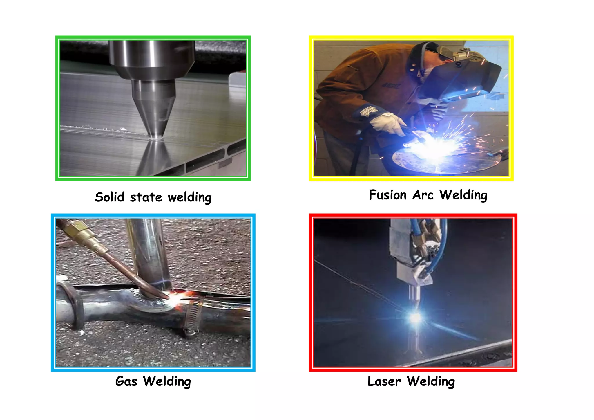
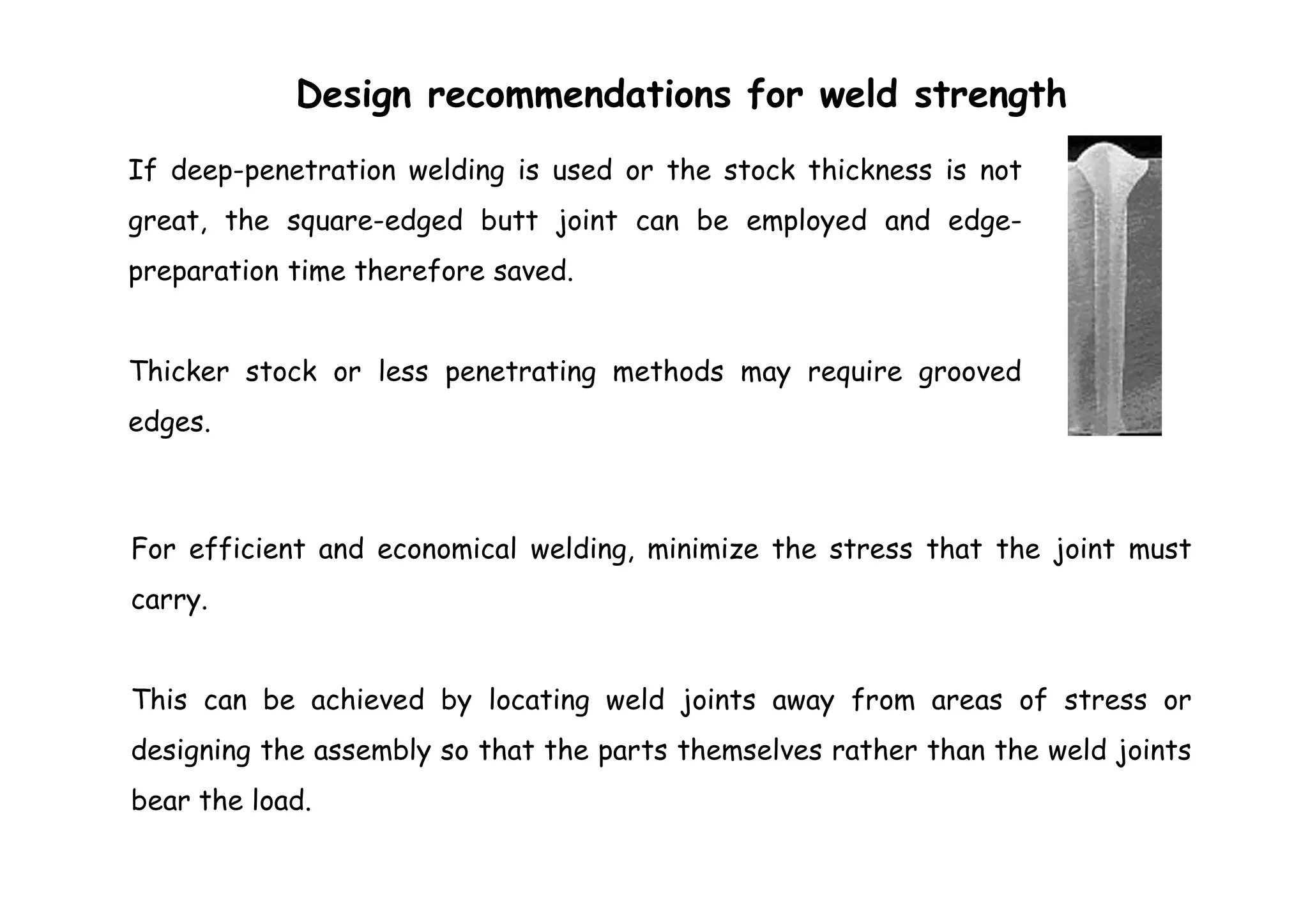
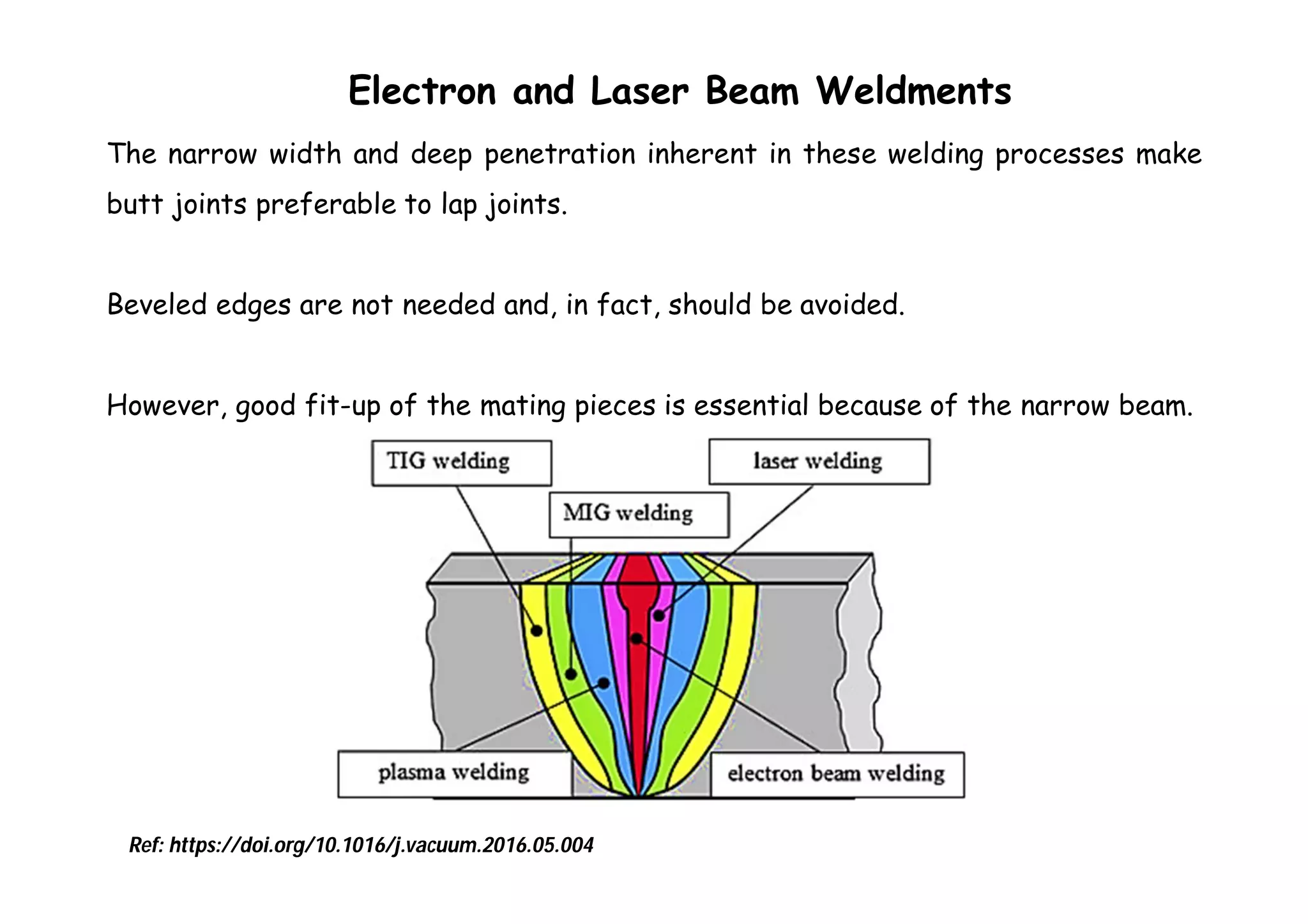
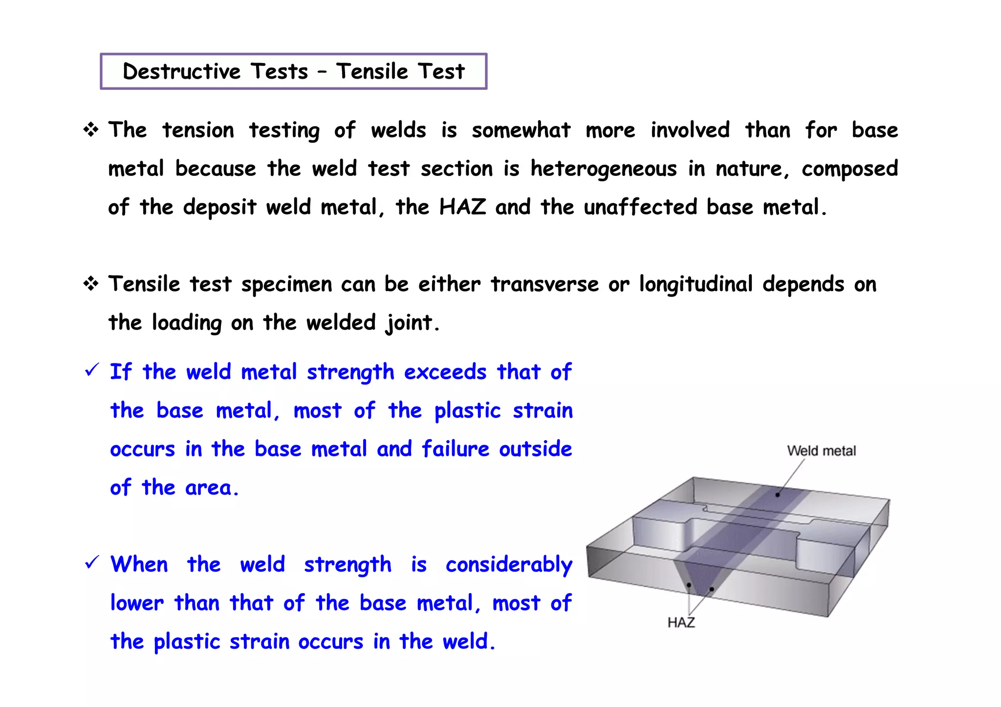
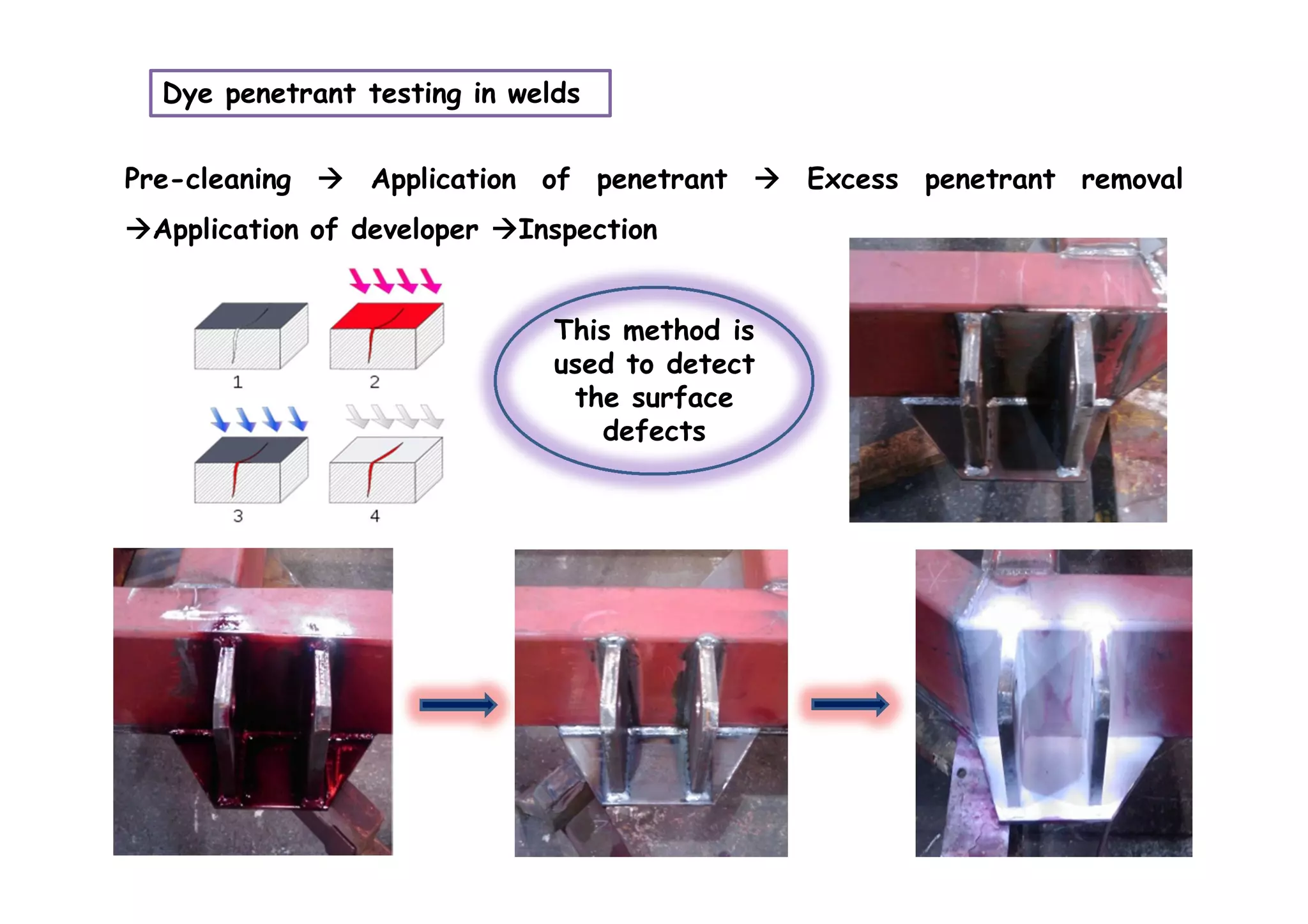
Reference:
James G. Bralla, Design for manufacturability Hand
book, McGraw Hill Publications
Image: Michael Ashby, Materials Selection in Mechanical Design
Classification of commercial welding processesClassification of commercial welding processes
Gas Welding
Electric Arc
welding
High density
beam welding
Oxyacetylene welding SMAW
GTAW, PAW
GMAW, FCAW
SAW, ESW
EBW
LBW
All the welding processes
involves these operations
Liquid/
Solid
interface
Solid/Solid
interface
FSW & FW
& RSW
Solid state welding Fusion Arc Welding
Gas Welding Laser Welding
 Interaction of different metals (similar & dissimilar)
 Interaction of metals with atmospheric gases within a short
period of time
Solubility of
atmospheric gases
and the effect of
shielding gases
with molten
weldment
Solid state
transformation
during cooling
after welding
Microstructural
changes in
weldment and
HAZ after
welding
Influence of
welding
parameters on
welding process
Effect of
impurities in
the weld
Changes in
Mechanical &
Corrosion
properties
Molten weld pool  semi solid weld  fully solidified weldment
What will happen, when the weld metal
is in hot liquid state ?
1. No distinct structure
2. No orderliness in the
arrangement of atoms
3. High degree of mobility
between atoms due to
heat energy involved in
welding.
When molten weld cools, atoms loose their energy and their
mobility and formed into a definite patterns.
These patterns are arranged in a three dimensional form and
forms a crystalline solid.
Efficiency of welding:
Where ,
Q = Heat transfer rate from the heat source to
the work piece
Qnominal = Nominal power of the heat source
Always efficiency is less than 100% due to the lose of heat to the
surroundings during welding.
Where, E = Arc voltage; I = welding current and V = Welding speed
Q = EI/VHeat input per unit length of the weld
Basic Weld Joints - TypesBasic Weld Joints - Types
Cruciform form joint
Joint Configurations
Different welding positionsDifferent welding positions
1G
2G
3G
4G
 Welded assemblies should be made up of as few parts as
possible.
 Metal forming and machining operations are almost always
less costly than welding.
Cost reduction
 Designers should develop at least part of the configuration of
their assemblies by forming and machining instead of welding.
 Weld joints should be placed so that there is room for easy
access of the welding nozzle. (Particularly for welding methods
that use a wire feed and a shielding gas).
 It is important that the nozzle be close to the welding point
so that the molten metal is well shielded.
Designers should specify the minimum amount of weld filler, with respect to
both fillet size and length, that meets functional requirements of the
assembly.
Image: V B Bhandari, Design of Machine Elements
 Tack welds should be specified if the application does not involve high
stresses or a leak proof construction.
 Designers have the responsibility for making whatever calculations, analyses,
or tests necessary to specify the sizes and types of welded joints rather
than simply to specify “Weld parts together.”
 Whenever possible assembly should be designed so that the welded joint is
horizontal, with the stick or electrode holder pointing downward during
welding.
 This position is the most rapid and convenient with all welding methods.
 It is preferable to locate welds out of sight rather than in locations where
special finishing operations are required for the sake of appearance.
Good fit-up of parts at the weld joint is essential not only for welding speed but
also for minimizing distortion of the finished weldment.
Especially with butt joints, edges of work pieces should be straight and uniform.
Often, the extra operation required to provide a straight edge will be less costly
than the extra welding labor required when the fit is not correct.
Poor and good fit-up of weld joints
Good fit-up’s on real time welded joints
Poor and good fit-up of weld joints
The build-up of weld fillets should be kept to a minimum. Additional material
in the convex portion of the fillet’s cross section does not add significantly to
the strength of the joint.
 When forgings or castings are part of a welded assembly, care should be taken
to ensure good fit-up of the parts to be welded.
 Untrimmed parting-line areas should not be included in the welded joint.
 The casting should also be designed so that the wall thickness of both parts to
be joined is equal at the joint. This ensures more rapid and less distortion-
prone welding.
 The joint should be designed so that it requires minimal edge preparation.
 lap joints are advisable to avoid the cost of close edge preparation and to
simplify fit-up problems.
 But lap joints are more difficult to clean, finish, and repair and frequently
have root defects.
 Joints that have natural grooves and thus need little or no edge
preparation.
 Equivalent of a grooved edge for the welded joint.
 Total operation time is reduced.
If machining after welding is required, welds should be placed away from
the material to be machined.
This will avoid machining problems which can occur in the heat-affected
zone.
 It is often advisable to utilize a number of welded subassemblies in the
fabrication of a large, complex final assembly.
 Subassemblies can be handled more easily.
 They can be positioned for easy access of the electrode, and the joint can be
kept horizontal during welding.
 When machining a groove on the end of a cylindrical component to be welded by
submerged arc, it sometimes is advantageous to include a backup strip as an
integral part of the component to be welded.
Causes for distortion
• Localized heating
• Non uniform stress distribution
Distortion occurs in these forms:
Longitudinal shrinkage
Transverse shrinkage
Angular distortion
Distortion
Types of Distortion
 Shrinkage
 Angular distortion
 Buckling deformation
 Rotational deformation
All the distortions are caused by the
shrinkage force generated due to the
thermal loading on the structure.
A single V groove butt weld leads to more distortion than the double V
groove butt weld of same thickness plate.
Welding in neutral axis will balance the shrinkage force of one side
against another side from the neutral axis.
Dimensional Inaccuracy caused by Distortion
Dimensional accuracy is very important in
welding. Heat flow in the direction
perpendicular to the weld line is more.
Transverse shrinkage > longitudinal
shrinkage
Weld
direction
Transverse shrinkage
longitudinal shrinkage
Heat transfer during welding
Minimizing Distortion
 Good fit of parts (maximum contact of all mating surfaces is desirable) is
important not only for minimum welding time but also for control of distortion.
 The more gap to fill, the greater the possible weldment distortion.
When dimensioning welded assemblies, it is essential that consideration be given
to the shrinkage inherent in each weld.
 Heavier sections are less prone to distortion from welding.
 Designers should consider the use of thicker, more rigid components.
 A short-flanged butt joint is often preferable for joining long sections of
thinner material.
Minimizing Distortion
Suited for autogenous welding
 Whenever possible, place welds opposite one another to reduce distortion
(shrinkage forces in the weld fillets are balanced).
To avoid angular distortion
 If sections of unequal thickness must be welded together, distortion can be
reduced by machining a groove in the thicker piece adjacent to the weld
joint.
Minimizing Distortion
 Avoid over welding – The bigger the weld, the greater the shrinkage.
Correctly sizing a weld not only minimizes distortion, but also saves weld
metal and time.
 Fewer weld passes — A fewer number of big passes results in less distortion
than a greater number of small passes with small electrodes. Shrinkage
accumulates from each weld pass.
If deep-penetration welding is used or the stock thickness is not
great, the square-edged butt joint can be employed and edge-
preparation time therefore saved.
Thicker stock or less penetrating methods may require grooved
edges.
Design recommendations for weld strength
For efficient and economical welding, minimize the stress that the joint must
carry.
This can be achieved by locating weld joints away from areas of stress or
designing the assembly so that the parts themselves rather than the weld joints
bear the load.
Weldments should be designed so that welds are placed to minimize stress
concentration in the weld fillet.
 Groove welds should be designed to be in either compression or tension.
 Fillet welds should be in shear only.
 Post weld heat treatment should be carried out if necessary.
The narrow width and deep penetration inherent in these welding processes make
butt joints preferable to lap joints.
Beveled edges are not needed and, in fact, should be avoided.
However, good fit-up of the mating pieces is essential because of the narrow beam.
Electron and Laser Beam Weldments
Ref: https://doi.org/10.1016/j.vacuum.2016.05.004
Economic Production Quantities
Oxyfuel Gas Welding  Low equipment and tooling cost, slower heating rate, used for repair and low-
quantity work.
Stick Welding  Low equipment and tooling cost, faster than gas welding, slower than with other arc-
welding processes (because of electrode changes and slag removal as well as welding time).
Submerged Arc Welding  Equipment and tooling costs are high, metal deposition rate, is quite rapid,
used for large-quantity work, particularly when seams are long.
Flux-Cored Welding  requires relatively expensive equipment, particularly if shielding gas also is used,
slag-removal labor is required, welding rates are high.
Gas-Metal Arc Welding  suitable for higher production levels, low in labor cost, electrode is fed
continuously.
Gas-Tungsten Arc Welding  Applicable to low-production work.
Plasma Arc Welding  2 to 5 times the cost of GTAW equipment, very rapid, producing welds at four or
more times the rate of other arc processes, capability to make deep-penetration welds.
Residual stresses
Residual stresses causes
• Stress corrosion cracking
• Hydrogen induced cracking
• Fatigue crack
Controlling residual stress
 Proper edge preparation
Minimize heat input
Preheating
No of passes during welding
Distortion
Stress pattern in longitudinal &Transverse
directions
Destructive Tests – Tensile Test
 The tension testing of welds is somewhat more involved than for base
metal because the weld test section is heterogeneous in nature, composed
of the deposit weld metal, the HAZ and the unaffected base metal.
 Tensile test specimen can be either transverse or longitudinal depends on
the loading on the welded joint.
 If the weld metal strength exceeds that of
the base metal, most of the plastic strain
occurs in the base metal and failure outside
of the area.
 When the weld strength is considerably
lower than that of the base metal, most of
the plastic strain occurs in the weld.
The tension-shear test is the most widely used method for determining
the strength of resistance spot welds.
Destructive Tests – Tension-shear Test
Destructive Tests – Bend Test
To measure the ductility and crack sensitivity of the welds
Dye penetrant testing in welds
Pre-cleaning  Application of penetrant  Excess penetrant removal
Application of developer Inspection
This method is
used to detect
the surface
defects
Magnetic particle Inspection in welds
Used for detecting surface and slightly subsurface discontinuities
in ferromagnetic materials such as iron, nickel, cobalt, and some of
their alloys.
The presence of a surface or subsurface discontinuity in the material allows
the magnetic flux to leak.
Ferrous iron particles are applied to the part, the particles will be attracted
to this area.
Ultrasonic Examinations
 This method that employs mechanical vibrations with a higher frequency
to detect the defects.
 Ultrasonic beam travels through a material, except when it is intercepted
and reflected by a discontinuity or by a change in material.
 When the pulse of ultrasonic waves strikes a discontinuity in the test
piece, it is reflected back to its point of origin.
Lack Of Fusion
Weld metal and the base metal are not fused together.
Possible Causes:
 Travel Speed Too Fast
 Insufficient root gap and low bevel angle
 Excessive filler wire diameter
Possible Cures:
 Increase Current and voltage
 Use Proper Travel Speed
Undercut
Edges of the joint to melt and drain into the weld
Possible causes:
 Excessive current
 Improper rod angle (Too small electrode angle)
 Arc length too long
 Slow speed
 Using an incorrect filler metal, because it will create greater
temperature gradients between the center of the weld and the
edges
Ways to minimize undercut:
 Shorten arc length
 Use correct arc length
 Lower machine setting
Porosity
Porosity is tiny holes in the weld. It can resemble a sponge and it
weakens a weld.
Common causes :
 Arc length too long
 Base metal not cleaned/impurities
 Electrode contamination/moisture
Solutions for porosity:
 Clean base metal
 Shorten arc length
 Use good dry electrodes
Overlap
Overlap is where the edges of the weld bead is not fused to the
base metal. It appears as if the weld is just sitting on top of the
metal.
Common causes:
 Travel speed too slow
 Welding machine setting too
low
Possible solutions:
 Use correct machine setting
 Increase travel speed
UNACCEPTABLE
WELD PROFILES SPATTER
UNDERFILL EXCESSIVE REINFORCEMENT

Design for welding by A Vinoth Jebaraj

  • 1.
    Reference: James G. Bralla,Design for manufacturability Hand book, McGraw Hill Publications
  • 2.
    Image: Michael Ashby,Materials Selection in Mechanical Design
  • 3.
    Classification of commercialwelding processesClassification of commercial welding processes Gas Welding Electric Arc welding High density beam welding Oxyacetylene welding SMAW GTAW, PAW GMAW, FCAW SAW, ESW EBW LBW All the welding processes involves these operations Liquid/ Solid interface Solid/Solid interface FSW & FW & RSW
  • 4.
    Solid state weldingFusion Arc Welding Gas Welding Laser Welding
  • 5.
     Interaction ofdifferent metals (similar & dissimilar)  Interaction of metals with atmospheric gases within a short period of time Solubility of atmospheric gases and the effect of shielding gases with molten weldment Solid state transformation during cooling after welding Microstructural changes in weldment and HAZ after welding Influence of welding parameters on welding process Effect of impurities in the weld Changes in Mechanical & Corrosion properties
  • 6.
    Molten weld pool semi solid weld  fully solidified weldment What will happen, when the weld metal is in hot liquid state ? 1. No distinct structure 2. No orderliness in the arrangement of atoms 3. High degree of mobility between atoms due to heat energy involved in welding. When molten weld cools, atoms loose their energy and their mobility and formed into a definite patterns. These patterns are arranged in a three dimensional form and forms a crystalline solid.
  • 7.
    Efficiency of welding: Where, Q = Heat transfer rate from the heat source to the work piece Qnominal = Nominal power of the heat source Always efficiency is less than 100% due to the lose of heat to the surroundings during welding. Where, E = Arc voltage; I = welding current and V = Welding speed Q = EI/VHeat input per unit length of the weld
  • 8.
    Basic Weld Joints- TypesBasic Weld Joints - Types Cruciform form joint
  • 9.
  • 10.
    Different welding positionsDifferentwelding positions 1G 2G 3G 4G
  • 11.
     Welded assembliesshould be made up of as few parts as possible.  Metal forming and machining operations are almost always less costly than welding. Cost reduction
  • 12.
     Designers shoulddevelop at least part of the configuration of their assemblies by forming and machining instead of welding.  Weld joints should be placed so that there is room for easy access of the welding nozzle. (Particularly for welding methods that use a wire feed and a shielding gas).  It is important that the nozzle be close to the welding point so that the molten metal is well shielded.
  • 13.
    Designers should specifythe minimum amount of weld filler, with respect to both fillet size and length, that meets functional requirements of the assembly. Image: V B Bhandari, Design of Machine Elements
  • 14.
     Tack weldsshould be specified if the application does not involve high stresses or a leak proof construction.
  • 15.
     Designers havethe responsibility for making whatever calculations, analyses, or tests necessary to specify the sizes and types of welded joints rather than simply to specify “Weld parts together.”  Whenever possible assembly should be designed so that the welded joint is horizontal, with the stick or electrode holder pointing downward during welding.  This position is the most rapid and convenient with all welding methods.  It is preferable to locate welds out of sight rather than in locations where special finishing operations are required for the sake of appearance.
  • 16.
    Good fit-up ofparts at the weld joint is essential not only for welding speed but also for minimizing distortion of the finished weldment. Especially with butt joints, edges of work pieces should be straight and uniform. Often, the extra operation required to provide a straight edge will be less costly than the extra welding labor required when the fit is not correct. Poor and good fit-up of weld joints
  • 17.
    Good fit-up’s onreal time welded joints
  • 18.
    Poor and goodfit-up of weld joints The build-up of weld fillets should be kept to a minimum. Additional material in the convex portion of the fillet’s cross section does not add significantly to the strength of the joint.
  • 19.
     When forgingsor castings are part of a welded assembly, care should be taken to ensure good fit-up of the parts to be welded.  Untrimmed parting-line areas should not be included in the welded joint.  The casting should also be designed so that the wall thickness of both parts to be joined is equal at the joint. This ensures more rapid and less distortion- prone welding.
  • 20.
     The jointshould be designed so that it requires minimal edge preparation.  lap joints are advisable to avoid the cost of close edge preparation and to simplify fit-up problems.  But lap joints are more difficult to clean, finish, and repair and frequently have root defects.
  • 21.
     Joints thathave natural grooves and thus need little or no edge preparation.  Equivalent of a grooved edge for the welded joint.  Total operation time is reduced.
  • 22.
    If machining afterwelding is required, welds should be placed away from the material to be machined. This will avoid machining problems which can occur in the heat-affected zone.
  • 23.
     It isoften advisable to utilize a number of welded subassemblies in the fabrication of a large, complex final assembly.  Subassemblies can be handled more easily.  They can be positioned for easy access of the electrode, and the joint can be kept horizontal during welding.  When machining a groove on the end of a cylindrical component to be welded by submerged arc, it sometimes is advantageous to include a backup strip as an integral part of the component to be welded.
  • 24.
    Causes for distortion •Localized heating • Non uniform stress distribution Distortion occurs in these forms: Longitudinal shrinkage Transverse shrinkage Angular distortion Distortion
  • 25.
    Types of Distortion Shrinkage  Angular distortion  Buckling deformation  Rotational deformation All the distortions are caused by the shrinkage force generated due to the thermal loading on the structure. A single V groove butt weld leads to more distortion than the double V groove butt weld of same thickness plate.
  • 26.
    Welding in neutralaxis will balance the shrinkage force of one side against another side from the neutral axis.
  • 27.
    Dimensional Inaccuracy causedby Distortion Dimensional accuracy is very important in welding. Heat flow in the direction perpendicular to the weld line is more. Transverse shrinkage > longitudinal shrinkage Weld direction Transverse shrinkage longitudinal shrinkage
  • 28.
  • 29.
    Minimizing Distortion  Goodfit of parts (maximum contact of all mating surfaces is desirable) is important not only for minimum welding time but also for control of distortion.  The more gap to fill, the greater the possible weldment distortion. When dimensioning welded assemblies, it is essential that consideration be given to the shrinkage inherent in each weld.
  • 30.
     Heavier sectionsare less prone to distortion from welding.  Designers should consider the use of thicker, more rigid components.  A short-flanged butt joint is often preferable for joining long sections of thinner material. Minimizing Distortion Suited for autogenous welding  Whenever possible, place welds opposite one another to reduce distortion (shrinkage forces in the weld fillets are balanced). To avoid angular distortion
  • 31.
     If sectionsof unequal thickness must be welded together, distortion can be reduced by machining a groove in the thicker piece adjacent to the weld joint. Minimizing Distortion  Avoid over welding – The bigger the weld, the greater the shrinkage. Correctly sizing a weld not only minimizes distortion, but also saves weld metal and time.  Fewer weld passes — A fewer number of big passes results in less distortion than a greater number of small passes with small electrodes. Shrinkage accumulates from each weld pass.
  • 32.
    If deep-penetration weldingis used or the stock thickness is not great, the square-edged butt joint can be employed and edge- preparation time therefore saved. Thicker stock or less penetrating methods may require grooved edges. Design recommendations for weld strength For efficient and economical welding, minimize the stress that the joint must carry. This can be achieved by locating weld joints away from areas of stress or designing the assembly so that the parts themselves rather than the weld joints bear the load.
  • 33.
    Weldments should bedesigned so that welds are placed to minimize stress concentration in the weld fillet.
  • 34.
     Groove weldsshould be designed to be in either compression or tension.  Fillet welds should be in shear only.  Post weld heat treatment should be carried out if necessary.
  • 35.
    The narrow widthand deep penetration inherent in these welding processes make butt joints preferable to lap joints. Beveled edges are not needed and, in fact, should be avoided. However, good fit-up of the mating pieces is essential because of the narrow beam. Electron and Laser Beam Weldments Ref: https://doi.org/10.1016/j.vacuum.2016.05.004
  • 36.
    Economic Production Quantities OxyfuelGas Welding  Low equipment and tooling cost, slower heating rate, used for repair and low- quantity work. Stick Welding  Low equipment and tooling cost, faster than gas welding, slower than with other arc- welding processes (because of electrode changes and slag removal as well as welding time). Submerged Arc Welding  Equipment and tooling costs are high, metal deposition rate, is quite rapid, used for large-quantity work, particularly when seams are long. Flux-Cored Welding  requires relatively expensive equipment, particularly if shielding gas also is used, slag-removal labor is required, welding rates are high. Gas-Metal Arc Welding  suitable for higher production levels, low in labor cost, electrode is fed continuously. Gas-Tungsten Arc Welding  Applicable to low-production work. Plasma Arc Welding  2 to 5 times the cost of GTAW equipment, very rapid, producing welds at four or more times the rate of other arc processes, capability to make deep-penetration welds.
  • 37.
    Residual stresses Residual stressescauses • Stress corrosion cracking • Hydrogen induced cracking • Fatigue crack Controlling residual stress  Proper edge preparation Minimize heat input Preheating No of passes during welding Distortion Stress pattern in longitudinal &Transverse directions
  • 38.
    Destructive Tests –Tensile Test  The tension testing of welds is somewhat more involved than for base metal because the weld test section is heterogeneous in nature, composed of the deposit weld metal, the HAZ and the unaffected base metal.  Tensile test specimen can be either transverse or longitudinal depends on the loading on the welded joint.  If the weld metal strength exceeds that of the base metal, most of the plastic strain occurs in the base metal and failure outside of the area.  When the weld strength is considerably lower than that of the base metal, most of the plastic strain occurs in the weld.
  • 39.
    The tension-shear testis the most widely used method for determining the strength of resistance spot welds. Destructive Tests – Tension-shear Test Destructive Tests – Bend Test To measure the ductility and crack sensitivity of the welds
  • 40.
    Dye penetrant testingin welds Pre-cleaning  Application of penetrant  Excess penetrant removal Application of developer Inspection This method is used to detect the surface defects
  • 41.
    Magnetic particle Inspectionin welds Used for detecting surface and slightly subsurface discontinuities in ferromagnetic materials such as iron, nickel, cobalt, and some of their alloys. The presence of a surface or subsurface discontinuity in the material allows the magnetic flux to leak. Ferrous iron particles are applied to the part, the particles will be attracted to this area.
  • 42.
    Ultrasonic Examinations  Thismethod that employs mechanical vibrations with a higher frequency to detect the defects.  Ultrasonic beam travels through a material, except when it is intercepted and reflected by a discontinuity or by a change in material.  When the pulse of ultrasonic waves strikes a discontinuity in the test piece, it is reflected back to its point of origin.
  • 43.
    Lack Of Fusion Weldmetal and the base metal are not fused together. Possible Causes:  Travel Speed Too Fast  Insufficient root gap and low bevel angle  Excessive filler wire diameter Possible Cures:  Increase Current and voltage  Use Proper Travel Speed
  • 44.
    Undercut Edges of thejoint to melt and drain into the weld Possible causes:  Excessive current  Improper rod angle (Too small electrode angle)  Arc length too long  Slow speed  Using an incorrect filler metal, because it will create greater temperature gradients between the center of the weld and the edges Ways to minimize undercut:  Shorten arc length  Use correct arc length  Lower machine setting
  • 45.
    Porosity Porosity is tinyholes in the weld. It can resemble a sponge and it weakens a weld. Common causes :  Arc length too long  Base metal not cleaned/impurities  Electrode contamination/moisture Solutions for porosity:  Clean base metal  Shorten arc length  Use good dry electrodes
  • 46.
    Overlap Overlap is wherethe edges of the weld bead is not fused to the base metal. It appears as if the weld is just sitting on top of the metal. Common causes:  Travel speed too slow  Welding machine setting too low Possible solutions:  Use correct machine setting  Increase travel speed
  • 47.