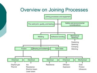
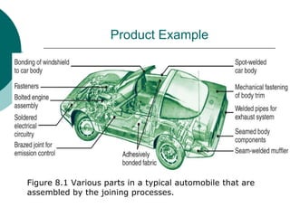
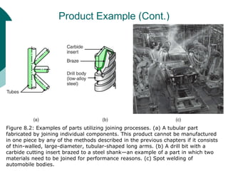
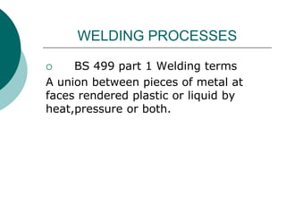
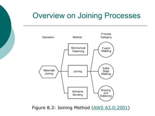
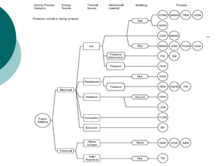
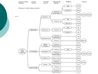
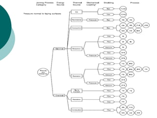
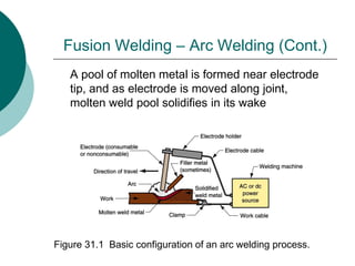
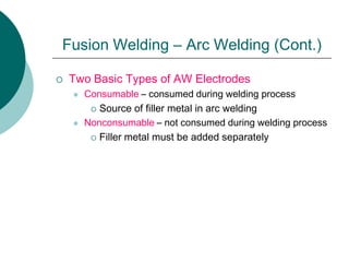
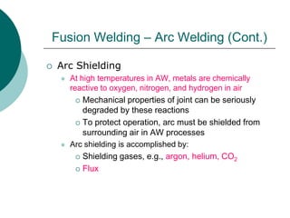
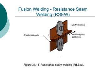
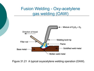
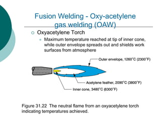
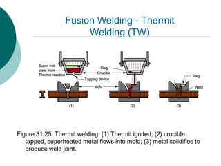
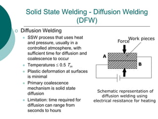
JOINING PROCESSES
An all-inclusive term covering processes
such as:
 Welding
 Brazing
 Soldering
 Adhesive bonding
 Mechanical fastening
Overview on Joining Processes
Why Joining Processes
 Some (even simple) products are too large to be made
by individual processes ( 3-D Hollow structural member, 5 m
diameter)
 Easier, more economical to manufacture & join
individual components (Cooking pot with handle)
 Products to be disassembled for maintenance
(Appliances; engines)
 Varying functionality of product (Carbide inserts in tool
steels; Brake shoes)
 Transportation + assembly is less costly (Shelving units;
Machinery)
Product Example
Figure 8.1 Various parts in a typical automobile that are
assembled by the joining processes.
Product Example (Cont.)
Figure 8.2: Examples of parts utilizing joining processes. (a) A tubular part
fabricated by joining individual components. This product cannot be manufactured
in one piece by any of the methods described in the previous chapters if it consists
of thin-walled, large-diameter, tubular-shaped long arms. (b) A drill bit with a
carbide cutting insert brazed to a steel shank—an example of a part in which two
materials need to be joined for performance reasons. (c) Spot welding of
automobile bodies.
WELDING PROCESSES
 BS 499 part 1 Welding terms
A union between pieces of metal at
faces rendered plastic or liquid by
heat,pressure or both.
Overview on Joining Processes
Figure 8.3: Joining Method (AWS A3.0:2001)
Fusion Welding
Fusion Welding
Fusion Welding
Fusion Welding
 Any welding process that uses fusion
of the base metal to make the weld
(AWS A3.0: 2001)
Fusion Welding – Arc Welding
 Arc Welding
 A fusion welding process in which coalescence of the
metals is achieved by the heat from an electric arc
between an electrode and the work
 Electric energy from the arc produces temperatures ~
10,000 F (5500 C), hot enough to melt any metal
 Most AW processes add filler metal to increase volume
and strength of weld joint
 An electric arc is a discharge of electric current across a
gap in a circuit
 It is sustained by an ionized column of gas (plasma)
through which the current flows
 To initiate the arc in AW, electrode is brought into
contact with work and then quickly separated from it by a
short distance
A pool of molten metal is formed near electrode
tip, and as electrode is moved along joint,
molten weld pool solidifies in its wake
Figure 31.1 Basic configuration of an arc welding process.
Fusion Welding – Arc Welding (Cont.)
 Two Basic Types of AW Electrodes
 Consumable – consumed during welding process
 Source of filler metal in arc welding
 Nonconsumable – not consumed during welding process
 Filler metal must be added separately
Fusion Welding – Arc Welding (Cont.)
 Arc Shielding
 At high temperatures in AW, metals are chemically
reactive to oxygen, nitrogen, and hydrogen in air
 Mechanical properties of joint can be seriously
degraded by these reactions
 To protect operation, arc must be shielded from
surrounding air in AW processes
 Arc shielding is accomplished by:
 Shielding gases, e.g., argon, helium, CO2
 Flux
Fusion Welding – Arc Welding (Cont.)
 Power Source in Arc Welding
 Direct current (DC) vs. Alternating current (AC)
 AC machines less expensive to purchase and
operate, but generally restricted to ferrous
metals
 DC equipment can be used on all metals and
is generally noted for better arc control
Fusion Welding – Arc Welding (Cont.)
 Resistance Welding (RW)
 A group of fusion welding processes that use a
combination of heat and pressure to accomplish
coalescence
 Heat generated by electrical resistance to current flow at
junction to be welded
 Principal RW process is resistance spot welding (RSW)
Fusion Welding – Resistance Welding
(Cont.)
Figure 31.12 Resistance
welding, showing the
components in spot
welding, the main
process in the RW
group.
Fusion Welding – Resistance
Welding (Cont.)
Fusion Welding – Resistance Welding
(Cont.)
 Components in Resistance Spot Welding
 Parts to be welded (usually sheet metal)
 Two opposing electrodes
 Means of applying pressure to squeeze parts between
electrodes
 Power supply from which a controlled current can be
applied for a specified time duration
Fusion Welding – Resistance Welding
(Cont.)
Advantages:
 No filler metal required
 High production rates possible
 Lends itself to mechanization and automation
 Lower operator skill level than for arc welding
 Good repeatability and reliability
Disadvantages:
 High initial equipment cost
 Limited to lap joints for most RW processes
 Skilled operators are required
 Bigger job thickness cannot be welded
Fusion Welding – Resistance
Welding (Cont.)
 Applications of resistance welding
 Joining sheets, bars and tubes.
 Making tubes and metal furniture.
 Welding aircraft and automobile parts.
 Making cutting tools.
 Making fuel tanks of cars, tractors etc.
 Making wire fabrics, grids, grills, mesh
weld, containers etc.
Fusion Welding - Resistance Spot
Welding (RSW)
 Resistance Spot Welding
 Process in which fusion of faying surfaces of a lap joint is
achieved at one location by opposing electrodes
 Used to join sheet metal parts using a series of spot welds
 Widely used in mass production of automobiles,
appliances, metal furniture, and other products made of
sheet metal
 Typical car body has ~ 10,000 spot welds
 Annual production of automobiles in the world is
measured in tens of millions of units
Figure 31.13 (a) Spot welding cycle, (b) plot of squeezing force & current
in cycle (1) parts inserted between electrodes, (2) electrodes close,
force applied, (3) current on, (4) current off, (5) electrodes opened.
Fusion Welding - Resistance Spot
Welding (RSW) (Cont.)
Fusion Welding - Resistance Seam
Welding (RSEW)
 Resistance Seam Welding (RSEW)
 Uses rotating wheel electrodes to produce a
series of overlapping spot welds along lap joint
 Can produce air-tight joints
 Applications:
 Gasoline tanks
 Automobile mufflers
 Various other sheet metal containers
Figure 31.15 Resistance seam welding (RSEW).
Fusion Welding - Resistance Seam
Welding (RSEW)
Fusion Welding - Oxyfuel Gas Welding
(OFW)
 Oxyfuel Gas Welding
 General term for welding operations that burn various fuels
mixed with oxygen
 OFW employs several types of gases, which is the primary
distinction among the members of this group
 Oxyfuel gas is also used in flame cutting torches to cut and
separate metal plates and other parts
Fusion Welding - Oxyfuel Gas Welding
(OFW)
 Alternatives Fuel Gases for OFW
 Acetylene
 Gasoline
 Hydrogen
 MPS and MAPP gas
 Propylene and Fuel Gas
 Butane, propane and butane/propane
mixes
Fusion Welding - Oxy-acetylene gas welding
(OAW)
 Oxy-acetylene gas welding (OAW)
 Oxy-acetylene gas welding is a group OFW process that
used acetylene gas as a fuel gas
 Most popular fuel among OFW group because it is capable of
higher temperatures than any other - up to 3480C
(6300F)
 Fusion welding performed by a high temperature flame from
combustion of acetylene and oxygen
 Flame is directed by a welding torch
 Filler metal is sometimes added
 Composition must be similar to base metal
 Filler rod often coated with flux to clean surfaces and prevent
oxidation
Figure 31.21 A typical oxyacetylene welding operation (OAW).
Fusion Welding - Oxy-acetylene
gas welding (OAW)
Fusion Welding - Oxy-acetylene gas
welding (OAW)
 Chemical reaction during burning
 Two stage chemical reaction of acetylene and
oxygen:
 First stage reaction:
C2H2 + O2  2CO + H2 + heat
 Second stage reaction:
2CO + H2 + 1.5O2  2CO2 + H2O + heat
 Oxyacetylene Torch
 Maximum temperature reached at tip of inner cone,
while outer envelope spreads out and shields work
surfaces from atmosphere
Figure 31.22 The neutral flame from an oxyacetylene torch
indicating temperatures achieved.
Fusion Welding - Oxy-acetylene
gas welding (OAW)
Fusion Welding - Other Processes
 FW processes that cannot be classified as arc,
resistance, or oxyfuel welding
 Use unique technologies to develop heat for
melting
 Applications are typically unique
 Processes include:
 Electron beam welding
 Laser beam welding
 Electroslag welding
 Thermit welding
Fusion Welding - Thermit Welding (TW)
 Thermit Welding (TW)
 FW process in which heat for coalescence is produced
by superheated molten metal from the chemical reaction
of thermite
 Thermite = mixture of Al and Fe3O4 fine powders that
produce an exothermic reaction when ignited
 Also used for incendiary bombs
 Filler metal obtained from liquid metal
 Process used for joining, but has more in common with
casting than welding
Figure 31.25 Thermit welding: (1) Thermit ignited; (2) crucible
tapped, superheated metal flows into mold; (3) metal solidifies to
produce weld joint.
Fusion Welding - Thermit
Welding (TW)
Fusion Welding - Thermit Welding (TW)
 Applications
 Joining of railroad rails
 Repair of cracks in large steel castings and forgings
 Weld surface is often smooth enough that no finishing is
required
Solid State Welding (SSW)
 Solid State Welding (SSW)
 Coalescence of part surfaces is achieved by:
 Pressure alone, or
 Heat and pressure
 If both heat and pressure are used, heat is not enough to melt
work surfaces
 For some SSW processes, time is also a factor
 No filler metal is added
 Each SSW process has its own way of creating a bond at the
faying surfaces
 Essential factors for a successful solid state weld are that the
two faying surfaces must be:
 Very clean
 In very close physical contact with each other to permit atomic bonding
Solid State Welding (Cont)
 SSW Advantages over FW Processes
 If no melting, then no heat affected zone, so metal
around joint retains original properties
 Many SSW processes produce welded joints that bond
the entire contact interface between two parts rather
than at distinct spots or seams
 Some SSW processes can be used to bond dissimilar
metals, without concerns about relative melting points,
thermal expansions, and other problems that arise in FW
Solid State Welding (Cont.)
 Processes under SSW group
 Forge welding
 Cold welding
 Roll welding
 Hot pressure welding
 Diffusion welding
 Explosion welding
 Friction welding
 Ultrasonic welding
Solid State Welding - Forge Welding
 Forge Welding
 SSW process in which
components to be joined are
heated to hot working temperature
range and then forged together by
hammering or similar means
 Historic significance in
development of manufacturing
technology
 Process dates from about
1000 B.C., when blacksmiths
learned to weld two pieces of
metal
Solid State Welding - Cold Welding
(CW)
 Cold Welding (CW)
 SSW process done by applying high
pressure between clean contacting
surfaces at room temperature
 Cleaning usually done by degreasing
and wire brushing immediately before
joining
 No heat is applied, but deformation
raises work temperature
 At least one of the metals, preferably
both, must be very ductile
 Soft aluminum and copper suited
to CW
 Applications: making electrical
connections
Dies
WorkpieceWorkpiece
Before welding
After welding
Solid State Welding - Roll Welding
(ROW)
 SSW process in which pressure sufficient to cause
coalescence is applied by means of rolls, either with or
without external heat
 Variation of either forge welding or cold welding, depending
on whether heating of workparts is done prior to process
 If no external heat, called cold roll welding
 If heat is supplied, hot roll welding
Solid State Welding - Roll Welding
(ROW)
 Applications
 Cladding stainless steel to mild or low alloy steel for
corrosion resistance
 Bimetallic strips for measuring temperature
 "Sandwich" coins for U.S mint
Solid State Welding - Diffusion Welding
(DFW)
 Diffusion Welding
 SSW process that uses heat
and pressure, usually in a
controlled atmosphere, with
sufficient time for diffusion and
coalescence to occur
 Temperatures  0.5 Tm
 Plastic deformation at surfaces
is minimal
 Primary coalescence
mechanism is solid state
diffusion
 Limitation: time required for
diffusion can range from
seconds to hours
Work pieces
Schematic representation of
diffusion welding using
electrical resistance for heating
A
B
Force
Solid State Welding - Diffusion Welding
(DFW)
 DFW Applications
 Joining of high-strength and refractory metals in
aerospace and nuclear industries
 Can be used to join either similar and dissimilar metals
 For joining dissimilar metals, a filler layer of different
metal is often sandwiched between base metals to
promote diffusion
Solid State Welding - Explosion
Welding (EXW)
 Explosion Welding (EXW)
 SSW process in which rapid coalescence of two metallic
surfaces is caused by the energy of a detonated
explosive
 No filler metal used
 No external heat applied
 No diffusion occurs - time is too short
 Bonding is metallurgical, combined with mechanical
interlocking that results from a rippled or wavy interface
between the metals
 Commonly used to bond two dissimilar metals, in
particular to clad one metal on top of a base metal over
large areas
Figure 31.27 Explosive welding (EXW): (1) setup in the
parallel configuration, and (2) during detonation of the
explosive charge.
Solid State Welding -
Explosion Welding (EXW)
Solid State Welding - Friction Welding
(FRW)
 SSW process in which coalescence is achieved
by frictional heat combined with pressure
 When properly carried out, no melting occurs at
faying surfaces
 No filler metal, flux, or shielding gases normally
used
 Process yields a narrow HAZ
 Can be used to join dissimilar metals
 Widely used commercial process, amenable to
automation and mass production
Figure 31.28 Friction welding (FRW): (1) rotating part, no contact; (2)
parts brought into contact to generate friction heat; (3) rotation
stopped and axial pressure applied; and (4) weld created.
Solid State Welding -
Friction Welding (FRW)
Solid State Welding - Friction Welding
(FRW)
 Two Types of Friction Welding
1. Continuous-drive friction welding
 One part is driven at constant rpm against
stationary part to cause friction heat at
interface
 At proper temperature, rotation is stopped
and parts are forced together
2. Inertia friction welding
 Rotating part is connected to flywheel,
which is brought up to required speed
 Flywheel is disengaged from drive, and
parts are forced together
Solid State Welding - Friction Welding
(FRW)
Applications:
 Shafts and tubular parts
 Industries: automotive, aircraft, farm equipment,
petroleum and natural gas
Limitations:
 At least one of the parts must be rotational
 Flash must usually be removed
 Upsetting reduces the part lengths (which must be
taken into consideration in product design)
Solid State Welding - Ultrasonic
Welding (USW)
 Two components are held together, oscillatory
shear stresses of ultrasonic frequency are applied
to interface to cause coalescence
 Oscillatory motion breaks down any surface films
to allow intimate contact and strong metallurgical
bonding between surfaces
 Although heating of surfaces occurs,
temperatures are well below Tm
 No filler metals, fluxes, or shielding gases
 Generally limited to lap joints on soft materials
such as aluminum and copper
Figure 31.29 Ultrasonic welding (USW): (a) general setup for
a lap joint; and (b) close-up of weld area.
Ultrasonic Welding
Solid State Welding - Ultrasonic
Welding
 Applications
 Wire terminations and splicing in electrical and
electronics industry
 Eliminates need for soldering
 Assembly of aluminum sheet metal panels
 Welding of tubes to sheets in solar panels
 Assembly of small parts in automotive industry
Weld Quality
 Concerned with obtaining an acceptable
weld joint that is strong and absent of
defects, and the methods of inspecting and
testing the joint to assure its quality
 Topics:
 Residual stresses and distortion
 Welding defects
 Inspection and testing methods
Weld Quality
 Residual Stresses and Distortion
 Rapid heating and cooling in localized regions during
FW result in thermal expansion and contraction that
cause residual stresses
 These stresses, in turn, cause distortion and warpage
 Situation in welding is complicated because:
 Heating is very localized
 Melting of base metals in these regions
 Location of heating and melting is in motion (at
least in AW)
Weld Quality
 Techniques to Minimize Warpage
 Welding fixtures to physically restrain parts
 Heat sinks to rapidly remove heat
 Tack welding at multiple points along joint to create a
rigid structure prior to seam welding
 Selection of welding conditions (speed, amount of filler
metal used, etc.) to reduce warpage
 Preheating base parts
 Stress relief heat treatment of welded assembly
 Proper design of weldment
Weld Quality - Welding
Defect/Imperfection
 Imperfection is any deviation from the ideal weld.
 Defect is an unacceptable imperfection
 A perfect weld joint, when subjected to an external force,
provide a distribution of stress throughout its volume which is
not significantly greater than parent metal.
Weld Quality - Welding
Defect/Imperfection
 Cracks
 Fracture-type interruptions either in weld or in base metal
adjacent to weld
 Serious defect because it is a discontinuity in the metal that
significantly reduces strength
 Caused by embrittlement or low ductility of weld and/or base
metal combined with high restraint during contraction
 In general, this defect must be repaired
Weld Quality - Welding
Defect/Imperfection
 Cavities
1. Porosity - small voids in weld metal formed by gases entrapped
during solidification. Caused by inclusion of atmospheric
gases, sulfur in weld metal, or surface contaminants
2. Shrinkage voids - cavities formed by shrinkage during
solidification. Cause by terminated arc at the end of a weld run
1 2
Weld Quality - Welding
Defect/Imperfection
 Solid inclusions - nonmetallic material entrapped in
weld metal
 Most common form is slag inclusions generated during AW
processes that use flux
 Instead of floating to top of weld pool, globules of slag become
encased during solidification
 Metallic oxides that form during welding of certain metals such
as aluminum, which normally has a surface coating of Al2O3
 Incomplete Fusion
 Also known as lack of fusion, it is simply a weld bead in which
fusion has not occurred throughout entire cross section of joint
Weld Quality - Welding
Defect/Imperfection
Weld Quality - Welding
Defect/Imperfection
o Lack of Smoothly Blended Surfaces
Weld Quality - Welding
Defect/Imperfection
o Miscellaneous defect
Misalignment Arc strikes
Spatter Burn Through
Inspection and Testing Methods
 Visual inspection
 Nondestructive evaluation
 Destructive testing
Inspection and Testing Methods –
Visual Inspection
 Visual Inspection
 Most widely used welding inspection method
 Human inspector visually examines for:
 Conformance to dimensions
 Warpage
 Cracks, cavities, incomplete fusion, and
other surface defects
 Limitations:
 Only surface defects are detectable
 Welding inspector must also determine if
additional tests are warranted
Inspection and Testing Methods –
Nondestructive Evaluation (NDE) Tests
 Nondestructive Evaluation (NDE) Tests
 Ultrasonic testing - high frequency sound waves
directed through specimen - cracks, inclusions are
detected by loss in sound transmission
 Radiographic testing - x-rays or gamma radiation
provide photograph of internal flaws
 Dye-penetrant and fluorescent-penetrant tests -
methods for detecting small cracks and cavities that
are open at surface
 Magnetic particle testing – iron filings sprinkled on
surface reveal subsurface defects by distorting
magnetic field in part
Inspection and Testing Methods –
Destructive Testing
 Destructive Testing
 Tests in which weld is destroyed either during testing or
to prepare test specimen
 Mechanical tests - purpose is similar to conventional
testing methods such as tensile tests, shear tests, etc
 Metallurgical tests - preparation of metallurgical
specimens (e.g., photomicrographs) of weldment to
examine metallic structure, defects, extent and condition
of heat affected zone, and similar phenomena
Weldability Factors - Welding Process
 Welding Process
 Some metals or metal combinations can be readily
welded by one process but are difficult to weld by
others
 Example: stainless steel readily welded by most AW
and RW processes, but difficult to weld by OFW
Weldability Factors – Base Metal
 Base Metal
 Some metals melt too easily; e.g., aluminum
 Metals with high thermal conductivity transfer heat
away from weld, which causes problems; e.g., copper
 High thermal expansion and contraction in metal
causes distortion problems
 Dissimilar metals pose problems in welding when
their physical and/or mechanical properties are
substantially different
Weldability Factors - Other Factors
 Filler metal
 Must be compatible with base metal(s)
 In general, elements mixed in liquid state that
form a solid solution upon solidification will
not cause a problem
 Surface conditions
 Moisture can result in porosity in fusion zone
 Oxides and other films on metal surfaces can
prevent adequate contact and fusion
Design Considerations in Welding
 Design for welding - product should be designed
from the start as a welded assembly, and not as a
casting or forging or other formed shape
 Minimum parts - welded assemblies should
consist of fewest number of parts possible
 Example: usually more cost efficient to perform
simple bending operations on a part than to
weld an assembly from flat plates and sheets
Arc Welding Design Guidelines
 Good fit-up of parts - to maintain dimensional
control and minimize distortion
 Machining is sometimes required to achieve
satisfactory fit-up
 Assembly must allow access for welding gun to
reach welding area
 Design of assembly should allow flat welding to
be performed as much as possible, since this
is fastest and most convenient welding position
Figure 31.35 Welding positions (defined here for groove
welds): (a) flat, (b) horizontal, (c) vertical, and (d)
overhead.
 Flat welding is best position
 Overhead welding is most difficult
Arc Welding Positions
BRAZING, SOLDERING, AND
ADHESIVE BONDING
1. Brazing
2. Soldering
3. Adhesive Bonding
Overview of Brazing and Soldering
 Both use filler metals to permanently join metal
parts, but there is no melting of base metals
 When to use brazing or soldering instead of
fusion welding:
 Metals have poor weldability
 Dissimilar metals are to be joined
 Intense heat of welding may damage
components being joined
 Geometry of joint not suitable for welding
 High strength is not required
Overview of Adhesive Bonding
 Uses forces of attachment between a filler
material and two closely-spaced surfaces to bond
the parts
 Filler material in adhesive bonding is not
metallic
 Joining process can be carried out at room
temperature or only modestly above
Brazing
 Joining process in which a filler metal is melted
and distributed by capillary action between faying
surfaces of metal parts being joined
 No melting of base metals occurs
 Only the filler melts
 Filler metal Tm greater than 450C (840F) but
less than Tm of base metal(s) to be joined
Strength of Brazed Joint
 If joint is properly designed and brazing operation
is properly performed, solidified joint will be
stronger than filler metal out of which it was
formed
 Why?
 Small part clearances used in brazing
 Metallurgical bonding that occurs between
base and filler metals
 Geometric constrictions imposed on joint by
base parts
Brazing Compared to Welding
 Any metals can be joined, including dissimilar
metals
 Can be performed quickly and consistently,
permitting high production rates
 Multiple joints can be brazed simultaneously
 Less heat and power required than FW
 Problems with HAZ in base metal are reduced
 Joint areas that are inaccessible by many welding
processes can be brazed; capillary action draws
molten filler metal into joint
Disadvantages and Limitations of
Brazing
 Joint strength is generally less than a welded joint
 Joint strength is likely to be less than the base
metals
 High service temperatures may weaken a brazed
joint
 Color of brazing metal may not match color of
base metal parts, a possible aesthetic
disadvantage
Brazing Applications
 Automotive (e.g., joining tubes and pipes)
 Electrical equipment (e.g., joining wires and
cables)
 Cutting tools (e.g., brazing cemented carbide
inserts to shanks)
 Jewelry
 Chemical process industry
 Plumbing and heating contractors join metal pipes
and tubes by brazing
 Repair and maintenance work
Brazed Joints
 Butt and lap joints common
 Geometry of butt joints is usually adapted for
brazing
 Lap joints are more widely used, since they
provide larger interface area between parts
 Filler metal in a brazed lap joint is bonded to base
parts throughout entire interface area, rather than
only at edges
Figure 32.1 (a) Conventional butt joint, and adaptations of
the butt joint for brazing: (b) scarf joint, (c) stepped butt
joint, (d) increased cross-section of the part at the joint.
Butt Joints for Brazing
Figure 32.2 (a) Conventional lap joint, and adaptations of the lap
joint for brazing: (b) cylindrical parts, (c) sandwiched parts, and
(d) use of sleeve to convert butt joint into lap joint.
Lap Joints for Brazing
Some Filler Metals for Brazing
Base metal(s) Filler metal(s)
Aluminum Aluminum and silicon
Nickel-copper alloy Copper
Copper Copper and phosphorous
Steel, cast iron Copper and zinc
Stainless steel Gold and silver
Desirable Brazing Metal Characteristics
 Melting temperature of filler metal is compatible
with base metal
 Low surface tension in liquid phase for good
wettability
 High fluidity for penetration into interface
 Capable of being brazed into a joint of adequate
strength for application
 Avoid chemical and physical interactions with
base metal (e.g., galvanic reaction)
Figure 32.4 Several techniques for applying filler metal in brazing:
(a) torch and filler rod. Sequence: (1) before, and (2) after.
Applying Filler Metal
Figure 32.4 Several techniques for applying filler metal in brazing:
(b) ring of filler metal at entrance of gap. Sequence: (1) before,
and (2) after.
Applying Filler Metal
Brazing Fluxes
 Similar purpose as in welding; they dissolve,
combine with, and otherwise inhibit formation of
oxides and other unwanted byproducts in brazing
process
 Characteristics of a good flux include:
 Low melting temperature
 Low viscosity so it can be displaced by filler
metal
 Facilitates wetting
 Protects joint until solidification of filler metal
Heating Methods in Brazing
 Torch Brazing - torch directs flame against work in
vicinity of joint
 Furnace Brazing - furnace supplies heat
 Induction Brazing – heating by electrical
resistance to high-frequency current in work
 Resistance Brazing - heating by electrical
resistance in parts
 Dip Brazing - molten salt or molten metal bath
 Infrared Brazing - uses high-intensity infrared
lamp
Soldering
 Joining process in which a filler metal with
Tm less than or equal to 450C (840F) is
melted and distributed by capillary action
between faying surfaces of metal parts being
joined
 No melting of base metals, but filler metal
wets and combines with base metal to form
metallurgical bond
 Soldering similar to brazing, and many of the
same heating methods are used
 Filler metal called solder
 Most closely associated with electrical and
electronics assembly (wire soldering)
Soldering Advantages / Disadvantages
Advantages:
 Lower energy than brazing or fusion welding
 Variety of heating methods available
 Good electrical and thermal conductivity in joint
 Easy repair and rework
Disadvantages:
 Low joint strength unless reinforced by
mechanically means
 Possible weakening or melting of joint in elevated
temperature service
Filler metal / Solder
 Usually alloys of tin (Sn) and lead (Pb). Both
metals have low Tm
 Lead is poisonous and its percentage is
minimized in most solders
 Tin is chemically active at soldering
temperatures and promotes wetting action
for successful joining
 In soldering copper, copper and tin form
intermetallic compounds that strengthen
bond
 Silver and antimony also used in soldering
alloys
Figure 32.8 Techniques for securing the joint by mechanical means prior
to soldering in electrical connections: (a) crimped lead wire on PC
board; (b) plated through-hole on PC board to maximize solder
contact surface; (c) hooked wire on flat terminal; and (d) twisted
wires.
Mechanical Means to Secure Joint
Functions of Soldering Fluxes
 Be molten at soldering temperatures
 Remove oxide films and tarnish from base part
surfaces
 Prevent oxidation during heating
 Promote wetting of faying surfaces
 Be readily displaced by molten solder during
process
 Leave residue that is non-corrosive and
nonconductive
Soldering Methods
 Many soldering methods same as for brazing,
except less heat and lower temperatures are
required
 Additional methods:
 Hand soldering – manually operated soldering
gun
 Wave soldering – soldering of multiple lead
wires in printed circuit cards
 Reflow soldering –used for surface mount
components on printed circuit cards
Figure 32.9 Wave soldering, in which molten solder is
delivered up through a narrow slot onto the underside of a
printed circuit board to connect the component lead wires.
Wave Soldering
Adhesive Bonding
 Joining process in which a filler material is used to
hold two (or more) closely-spaced parts together
by surface attachment
 Used in a wide range of bonding and sealing
applications for joining similar and dissimilar
materials such as metals, plastics, ceramics,
wood, paper, and cardboard
 Considered a growth area because of
opportunities for increased applications
Adhesive Bonding - Terminology
 Adhesive = filler material, nonmetallic, usually a
polymer
 Adherends = parts being joined
 Structural adhesives – of greatest interest in
engineering, capable of forming strong,
permanent joints between strong, rigid adherends
Curing in Adhesive Bonding
 Process by which physical properties of the
adhesive are changed from liquid to solid, usually
by chemical reaction, to accomplish surface
attachment of parts
 Curing often aided by heat and/or a catalyst
 If heat used, temperatures are relatively low
 Curing takes time - a disadvantage in production
 Pressure sometimes applied between parts to
activate bonding process
Adhesive Bonding - Joint Strength
 Depends on strength of:
 Adhesive
 Attachment between adhesive and
adherends
 Attachment mechanisms:
 Chemical bonding – adhesive and
adherend form primary bond on curing
 Physical interactions - secondary
bonding forces between surface atoms
 Mechanical interlocking - roughness of
adherend causes adhesive to become
entangled in surface asperities
Adhesive Bonding - Joint Design
 Adhesive joints are not as strong as welded,
brazed, or soldered joints
 Joint contact area should be maximized
 Adhesive joints are strongest in shear and tension
 Joints should be designed so applied stresses
are of these types
 Adhesive bonded joints are weakest in cleavage
or peeling
 Joints should be designed to avoid these types
of stresses
Figure 32.10 Types of stresses that must be
considered in adhesive bonded joints: (a) tension,
(b) shear, (c) cleavage, and (d) peeling.
Types of Stresses in Adhesive Bonding
Figure 32.11 Some joint designs for adhesive bonding: (a) through
(d) butt joints; (e) through (f) T-joints; (b) and (g) through (j)
corner joints.
Joint Designs in Adhesive Bonding
Adhesive Types
 Natural adhesives - derived from natural sources,
including gums, starch, dextrin, soya flour,
collagen
 Low-stress applications: cardboard cartons,
furniture, bookbinding, plywood
 Inorganic - based principally on sodium silicate
and magnesium oxychloride
 Low cost, low strength
 Synthetic adhesives - various thermoplastic and
thermosetting polymers
Synthetic Adhesives
 Most important category in manufacturing
 Synthetic adhesives cured by various
mechanisms:
 Mixing catalyst or reactive ingredient with
polymer prior to applying
 Heating to initiate chemical reaction
 Radiation curing, such as UV light
 Curing by evaporation of water
 Application as films or pressure-sensitive
coatings on surface of adherend
Applications of Adhesives
 Automotive, aircraft, building products,
shipbuilding
 Packaging industries
 Footwear
 Furniture
 Bookbinding
 Electrical and electronics
Surface Preparation
 For adhesive bonding to succeed, part
surfaces must be extremely clean
 Bond strength depends on degree of
adhesion between adhesive and adherend,
and this depends on cleanliness of surface
 For metals, solvent wiping often used for
cleaning, and abrading surface by
sandblasting improves adhesion
 For nonmetallic parts, surfaces are
sometimes mechanically abraded or
chemically etched to increase roughness
Application Methods
 Manual brushing and rolling
 Silk screening
 Flowing, using manually operated dispensers
 Spraying
 Automatic applicators
 Roll coating
Adhesive is dispensed
by a manually
controlled dispenser to
bond parts during
assembly (photo
courtesy of EFD Inc.).
Advantages of Adhesive Bonding
 Applicable to a wide variety of materials
 Bonding occurs over entire surface area of joint
 Low temperature curing avoids damage to parts
being joined
 Sealing as well as bonding
 Joint design is often simplified, e.g., two flat
surfaces can be joined without providing special
part features such as screw holes
Limitations of Adhesive Bonding
 Joints generally not as strong as other joining
methods
 Adhesive must be compatible with materials being
joined
 Service temperatures are limited
 Cleanliness and surface preparation prior to
application of adhesive are important
 Curing times can limit production rates
 Inspection of bonded joint is difficult
©2007 John Wiley &
Sons, Inc. M P Groover,
Fundamentals of
Modern Manufacturing
3/e
Mechanical Assembly Technology
1. Threaded Fasteners
2. Rivets and Eyelets
3. Assembly Methods Based on
Interference Fits
4. Other Mechanical Fastening
Methods
5. Molding Inserts and Integral
Fasteners
6. Design for Assembly
©2007 John Wiley &
Sons, Inc. M P Groover,
Fundamentals of
Modern Manufacturing
3/e
Mechanical Assembly Defined
Use of various fastening methods to
mechanically attach two or more
parts together
 In most cases, discrete hardware
components, called fasteners, are
added to the parts during assembly
 In other cases, fastening involves
shaping or reshaping of a
component, and no separate
fasteners are required
©2007 John Wiley &
Sons, Inc. M P Groover,
Fundamentals of
Modern Manufacturing
3/e
Products of Mechanical Assembly
 Many consumer products are
assembled largely by mechanical
fastening methods
 Examples: automobiles, large and small
appliances, telephones
 Many capital goods products are
assembled using mechanical
fastening methods
 Examples: commercial airplanes, trucks,
railway locomotives and cars, machine
tools
©2007 John Wiley &
Sons, Inc. M P Groover,
Fundamentals of
Modern Manufacturing
3/e
Two Major Types of Mechanical
Assembly
1. Methods that allow for disassembly
 Example: threaded fasteners
2. Methods that create a permanent
joint
 Example: rivets
Why Use Mechanical Assembly?
 Low cost
 Ease of manufacturing
 Easy in creating design
 Ease of assembly – can be
accomplished with relatively ease
by unskilled workers
 Minimum of special tooling required
 In a relatively short time
 Ease of disassembly – at least for
the methods that permit
disassembly
©2007 John Wiley &
Sons, Inc. M P Groover,
Fundamentals of
Modern Manufacturing
3/e
Threaded Fasteners
Discrete hardware components that
have external or internal threads for
assembly of parts
 Most important category of
mechanical assembly
 In nearly all cases, threaded
fasteners permit disassembly
 Common threaded fastener types
are screws, bolts, and nuts
©2007 John Wiley &
Sons, Inc. M P Groover,
Fundamentals of
Modern Manufacturing
3/e
Screws, Bolts, and Nuts
Screw - externally threaded fastener
generally assembled into a blind
threaded hole
Bolt - externally threaded fastener
inserted into through holes and
"screwed" into a nut on the opposite
side
Nut - internally threaded fastener
having standard threads that match
those on bolts of the same
diameter, pitch, and thread form
©2007 John Wiley & Sons, Inc. M P Groover, Fundamentals of Modern Manufacturing 3/e
Figure 33.1 Typical assemblies when screws and bolts
are used.
Screws, Bolts, and Nuts
©2007 John Wiley &
Sons, Inc. M P Groover,
Fundamentals of
Modern Manufacturing
3/e
Some Facts About Screws and
Bolts
 Screws and bolts come in a variety
of sizes, threads, and shapes
 Much standardization in threaded
fasteners, which promotes
interchangeability
 U.S. is converting to metric, further
reducing variations
 Differences between threaded
fasteners affect tooling
 Example: different screw head styles and
©2007 John Wiley & Sons, Inc. M P Groover, Fundamentals of Modern Manufacturing 3/e
Figure 33.2 Various head styles available on screws and
bolts.
Head Styles on Screws and Bolts
©2007 John Wiley &
Sons, Inc. M P Groover,
Fundamentals of
Modern Manufacturing
3/e
Types of Screws
 Greater variety than bolts, since
functions vary more
 Examples:
 Machine screws - generic type, generally
designed for assembly into tapped holes
 Cap screws - same geometry as machine
screws but made of higher strength
metals and to closer tolerances
©2007 John Wiley & Sons, Inc. M P Groover, Fundamentals of Modern Manufacturing 3/e
Hardened and designed for
assembly functions such as
fastening collars, gears, and
pulleys to shafts
Figure 33.3 (a) Assembly of collar to shaft using a setscrew;
(b) various setscrew geometries (head types and points).
Setscrews
©2007 John Wiley & Sons, Inc. M P Groover, Fundamentals of Modern Manufacturing 3/e
 Designed to form or cut
threads in a pre-existing hole
into which it is being turned
 Also called a tapping screw
Figure 33.4 Self-tapping
screws: thread-forming,
and thread-cutting.
Self-Tapping Screws
©2007 John Wiley &
Sons, Inc. M P Groover,
Fundamentals of
Modern Manufacturing
3/e
Screw Thread Inserts
Internally threaded plugs or wire coils
designed to be inserted into an
unthreaded hole and accept an
externally threaded fastener
 Assembled into weaker materials to
provide strong threads
 Upon assembly of screw into insert,
insert barrel expands into hole to
secure the assembly
©2007 John Wiley &
Sons, Inc. M P Groover,
Fundamentals of
Modern Manufacturing
3/e
Figure 33.6 Screw thread inserts: (a) before insertion, and
(b) after insertion into hole and screw is turned into insert.
Screw Thread Inserts
©2007 John Wiley &
Sons, Inc. M P Groover,
Fundamentals of
Modern Manufacturing
3/e
Washer
Hardware component often used with
threaded fasteners to ensure
tightness of the mechanical joint
 Simplest form = flat thin ring of
sheet metal
 Functions:
 Distribute stresses
 Provide support for large clearance holes
 Protect part surfaces and seal the joint
 Increase spring tension
 Resist inadvertent unfastening
©2007 John Wiley &
Sons, Inc. M P Groover,
Fundamentals of
Modern Manufacturing
3/e
Figure 33.8 Types of washers: (a) plain (flat) washers; (b) spring
washers, used to dampen vibration or compensate for wear; and
(c) lock washer designed to resist loosening of the bolt or screw.
Washer Types
©2007 John Wiley &
Sons, Inc. M P Groover,
Fundamentals of
Modern Manufacturing
3/e
Bolt Strength
Two measures:
 Tensile strength, which has the
traditional definition
 Proof strength - roughly equivalent
to yield strength
 Maximum tensile stress without
permanent deformation
©2007 John Wiley &
Sons, Inc. M P Groover,
Fundamentals of
Modern Manufacturing
3/e
Figure 33.9 Typical stresses acting on a bolted
joint.
Stresses in a Bolted Joint
©2007 John Wiley &
Sons, Inc. M P Groover,
Fundamentals of
Modern Manufacturing
3/e
Over-tightening in Bolted Joints
 Potential problem in assembly,
causing stresses that exceed
strength of fastener or nut
 Failure can occur in one of the
following ways:
1. Stripping of external threads
2. Stripping of internal threads
3. Bolt fails due to excessive tensile
stresses on cross-sectional area
 Tensile failure of cross section is
most common problem
©2007 John Wiley &
Sons, Inc. M P Groover,
Fundamentals of
Modern Manufacturing
3/e
Methods to Apply Required Torque
1. Operator feel - not very accurate,
but adequate for most assemblies
2. Torque wrench – indicates amount
of torque during tightening
3. Stall-motor - motorized wrench is
set to stall when required torque is
reached
4. Torque-turn tightening - fastener is
initially tightened to a low torque
level and then rotated a specified
©2007 John Wiley &
Sons, Inc. M P Groover,
Fundamentals of
Modern Manufacturing
3/e
Rivets
Unthreaded, headed pin used to
join two or more parts by
passing pin through holes in
parts and forming a second head
in the pin on the opposite side
 Widely used fasteners for
achieving a permanent
mechanically fastened joint
 Clearance hole into which rivet is
inserted must be close to the
diameter of the rivet
©2007 John Wiley &
Sons, Inc. M P Groover,
Fundamentals of
Modern Manufacturing
3/e
Figure 33.10 Five basic rivet types, also shown in assembled
configuration: (a) solid, (b) tubular, (c) semi-tubular, (d) bifurcated,
and (e) compression.
Types of Rivets
©2007 John Wiley &
Sons, Inc. M P Groover,
Fundamentals of
Modern Manufacturing
3/e
Applications and Advantages of
Rivets
 Used primarily for lap joints
 A primary fastening method in
aircraft and aerospace industries
 Advantages:
 High production rates
 Simplicity
 Dependability
 Low cost
©2007 John Wiley &
Sons, Inc. M P Groover,
Fundamentals of
Modern Manufacturing
3/e
Tooling and Methods for Rivets
1. Impact - pneumatic hammer
delivers a succession of blows to
upset rivet
2. Steady compression - riveting tool
applies a continuous squeezing
pressure to upset rivet
3. Combination of impact and
compression
©2007 John Wiley &
Sons, Inc. M P Groover,
Fundamentals of
Modern Manufacturing
3/e
Interference Fits
Assembly methods based on
mechanical interference between
two mating parts being joined
 The interference, either during
assembly or after joining, holds the
parts together
 Interference fit methods include:
 Press fitting
 Shrink and expansion fits
 Snap fits
 Retaining rings
©2007 John Wiley &
Sons, Inc. M P Groover,
Fundamentals of
Modern Manufacturing
3/e
Snap Fits
Joining of two parts in which
mating elements possess a
temporary interference during
assembly, but once assembled
they interlock
 During assembly, one or both parts
elastically deform to accommodate
temporary interference
 Usually designed for slight
interference after assembly
 Originally conceived as a method
ideally suited for industrial robots
©2007 John Wiley &
Sons, Inc. M P Groover,
Fundamentals of
Modern Manufacturing
3/e
Figure 33.13 Snap fit assembly, showing cross-sections of two
mating parts: (1) before assembly, and (2) parts snapped together.
Snap Fit Assembly
©2007 John Wiley &
Sons, Inc. M P Groover,
Fundamentals of
Modern Manufacturing
3/e
Retaining Ring
Fastener that snaps into a
circumferential groove on a shaft or
tube to form a shoulder
 Used to locate or restrict movement
of parts on a shaft
©2007 John Wiley &
Sons, Inc. M P Groover,
Fundamentals of
Modern Manufacturing
3/e
Design for Assembly (DFA)
 Keys to successful DFA:
1. Design product with as few parts as
possible
2. Design remaining parts so they are
easy to assemble
 Assembly cost is determined
largely in product design, when
the number of components in
the product and how they are
assembled is decided
 Once these decisions are made,
little can be done in manufacturing
©2007 John Wiley &
Sons, Inc. M P Groover,
Fundamentals of
Modern Manufacturing
3/e
DFA Guidelines
 Use modularity in product design
 Each subassembly should have a
maximum of 12 or so parts
 Design the subassembly around a base
part to which other components are
added
 Reduce the need for multiple
components to be handled at once
©2007 John Wiley &
Sons, Inc. M P Groover,
Fundamentals of
Modern Manufacturing
3/e
More DFA Guidelines
 Limit the required directions of
access
 Adding all components vertically from
above is the ideal
 Use high quality components
 Poor quality parts jams feeding and
assembly mechanisms
 Minimize threaded fasteners
 Use snap fit assembly

Topic 7 joining process welding brazing soldering fastening 160214

  • 1.
    JOINING PROCESSES An all-inclusiveterm covering processes such as:  Welding  Brazing  Soldering  Adhesive bonding  Mechanical fastening
  • 2.
  • 3.
    Why Joining Processes Some (even simple) products are too large to be made by individual processes ( 3-D Hollow structural member, 5 m diameter)  Easier, more economical to manufacture & join individual components (Cooking pot with handle)  Products to be disassembled for maintenance (Appliances; engines)  Varying functionality of product (Carbide inserts in tool steels; Brake shoes)  Transportation + assembly is less costly (Shelving units; Machinery)
  • 4.
    Product Example Figure 8.1Various parts in a typical automobile that are assembled by the joining processes.
  • 5.
    Product Example (Cont.) Figure8.2: Examples of parts utilizing joining processes. (a) A tubular part fabricated by joining individual components. This product cannot be manufactured in one piece by any of the methods described in the previous chapters if it consists of thin-walled, large-diameter, tubular-shaped long arms. (b) A drill bit with a carbide cutting insert brazed to a steel shank—an example of a part in which two materials need to be joined for performance reasons. (c) Spot welding of automobile bodies.
  • 6.
    WELDING PROCESSES  BS499 part 1 Welding terms A union between pieces of metal at faces rendered plastic or liquid by heat,pressure or both.
  • 7.
    Overview on JoiningProcesses Figure 8.3: Joining Method (AWS A3.0:2001)
  • 8.
  • 9.
  • 10.
  • 11.
    Fusion Welding  Anywelding process that uses fusion of the base metal to make the weld (AWS A3.0: 2001)
  • 12.
    Fusion Welding –Arc Welding  Arc Welding  A fusion welding process in which coalescence of the metals is achieved by the heat from an electric arc between an electrode and the work  Electric energy from the arc produces temperatures ~ 10,000 F (5500 C), hot enough to melt any metal  Most AW processes add filler metal to increase volume and strength of weld joint  An electric arc is a discharge of electric current across a gap in a circuit  It is sustained by an ionized column of gas (plasma) through which the current flows  To initiate the arc in AW, electrode is brought into contact with work and then quickly separated from it by a short distance
  • 13.
    A pool ofmolten metal is formed near electrode tip, and as electrode is moved along joint, molten weld pool solidifies in its wake Figure 31.1 Basic configuration of an arc welding process. Fusion Welding – Arc Welding (Cont.)
  • 14.
     Two BasicTypes of AW Electrodes  Consumable – consumed during welding process  Source of filler metal in arc welding  Nonconsumable – not consumed during welding process  Filler metal must be added separately Fusion Welding – Arc Welding (Cont.)
  • 15.
     Arc Shielding At high temperatures in AW, metals are chemically reactive to oxygen, nitrogen, and hydrogen in air  Mechanical properties of joint can be seriously degraded by these reactions  To protect operation, arc must be shielded from surrounding air in AW processes  Arc shielding is accomplished by:  Shielding gases, e.g., argon, helium, CO2  Flux Fusion Welding – Arc Welding (Cont.)
  • 16.
     Power Sourcein Arc Welding  Direct current (DC) vs. Alternating current (AC)  AC machines less expensive to purchase and operate, but generally restricted to ferrous metals  DC equipment can be used on all metals and is generally noted for better arc control Fusion Welding – Arc Welding (Cont.)
  • 17.
     Resistance Welding(RW)  A group of fusion welding processes that use a combination of heat and pressure to accomplish coalescence  Heat generated by electrical resistance to current flow at junction to be welded  Principal RW process is resistance spot welding (RSW) Fusion Welding – Resistance Welding (Cont.)
  • 18.
    Figure 31.12 Resistance welding,showing the components in spot welding, the main process in the RW group. Fusion Welding – Resistance Welding (Cont.)
  • 19.
    Fusion Welding –Resistance Welding (Cont.)  Components in Resistance Spot Welding  Parts to be welded (usually sheet metal)  Two opposing electrodes  Means of applying pressure to squeeze parts between electrodes  Power supply from which a controlled current can be applied for a specified time duration
  • 20.
    Fusion Welding –Resistance Welding (Cont.) Advantages:  No filler metal required  High production rates possible  Lends itself to mechanization and automation  Lower operator skill level than for arc welding  Good repeatability and reliability Disadvantages:  High initial equipment cost  Limited to lap joints for most RW processes  Skilled operators are required  Bigger job thickness cannot be welded
  • 21.
    Fusion Welding –Resistance Welding (Cont.)  Applications of resistance welding  Joining sheets, bars and tubes.  Making tubes and metal furniture.  Welding aircraft and automobile parts.  Making cutting tools.  Making fuel tanks of cars, tractors etc.  Making wire fabrics, grids, grills, mesh weld, containers etc.
  • 22.
    Fusion Welding -Resistance Spot Welding (RSW)  Resistance Spot Welding  Process in which fusion of faying surfaces of a lap joint is achieved at one location by opposing electrodes  Used to join sheet metal parts using a series of spot welds  Widely used in mass production of automobiles, appliances, metal furniture, and other products made of sheet metal  Typical car body has ~ 10,000 spot welds  Annual production of automobiles in the world is measured in tens of millions of units
  • 23.
    Figure 31.13 (a)Spot welding cycle, (b) plot of squeezing force & current in cycle (1) parts inserted between electrodes, (2) electrodes close, force applied, (3) current on, (4) current off, (5) electrodes opened. Fusion Welding - Resistance Spot Welding (RSW) (Cont.)
  • 24.
    Fusion Welding -Resistance Seam Welding (RSEW)  Resistance Seam Welding (RSEW)  Uses rotating wheel electrodes to produce a series of overlapping spot welds along lap joint  Can produce air-tight joints  Applications:  Gasoline tanks  Automobile mufflers  Various other sheet metal containers
  • 25.
    Figure 31.15 Resistanceseam welding (RSEW). Fusion Welding - Resistance Seam Welding (RSEW)
  • 26.
    Fusion Welding -Oxyfuel Gas Welding (OFW)  Oxyfuel Gas Welding  General term for welding operations that burn various fuels mixed with oxygen  OFW employs several types of gases, which is the primary distinction among the members of this group  Oxyfuel gas is also used in flame cutting torches to cut and separate metal plates and other parts
  • 27.
    Fusion Welding -Oxyfuel Gas Welding (OFW)  Alternatives Fuel Gases for OFW  Acetylene  Gasoline  Hydrogen  MPS and MAPP gas  Propylene and Fuel Gas  Butane, propane and butane/propane mixes
  • 28.
    Fusion Welding -Oxy-acetylene gas welding (OAW)  Oxy-acetylene gas welding (OAW)  Oxy-acetylene gas welding is a group OFW process that used acetylene gas as a fuel gas  Most popular fuel among OFW group because it is capable of higher temperatures than any other - up to 3480C (6300F)  Fusion welding performed by a high temperature flame from combustion of acetylene and oxygen  Flame is directed by a welding torch  Filler metal is sometimes added  Composition must be similar to base metal  Filler rod often coated with flux to clean surfaces and prevent oxidation
  • 29.
    Figure 31.21 Atypical oxyacetylene welding operation (OAW). Fusion Welding - Oxy-acetylene gas welding (OAW)
  • 30.
    Fusion Welding -Oxy-acetylene gas welding (OAW)  Chemical reaction during burning  Two stage chemical reaction of acetylene and oxygen:  First stage reaction: C2H2 + O2  2CO + H2 + heat  Second stage reaction: 2CO + H2 + 1.5O2  2CO2 + H2O + heat
  • 31.
     Oxyacetylene Torch Maximum temperature reached at tip of inner cone, while outer envelope spreads out and shields work surfaces from atmosphere Figure 31.22 The neutral flame from an oxyacetylene torch indicating temperatures achieved. Fusion Welding - Oxy-acetylene gas welding (OAW)
  • 32.
    Fusion Welding -Other Processes  FW processes that cannot be classified as arc, resistance, or oxyfuel welding  Use unique technologies to develop heat for melting  Applications are typically unique  Processes include:  Electron beam welding  Laser beam welding  Electroslag welding  Thermit welding
  • 33.
    Fusion Welding -Thermit Welding (TW)  Thermit Welding (TW)  FW process in which heat for coalescence is produced by superheated molten metal from the chemical reaction of thermite  Thermite = mixture of Al and Fe3O4 fine powders that produce an exothermic reaction when ignited  Also used for incendiary bombs  Filler metal obtained from liquid metal  Process used for joining, but has more in common with casting than welding
  • 34.
    Figure 31.25 Thermitwelding: (1) Thermit ignited; (2) crucible tapped, superheated metal flows into mold; (3) metal solidifies to produce weld joint. Fusion Welding - Thermit Welding (TW)
  • 35.
    Fusion Welding -Thermit Welding (TW)  Applications  Joining of railroad rails  Repair of cracks in large steel castings and forgings  Weld surface is often smooth enough that no finishing is required
  • 36.
    Solid State Welding(SSW)  Solid State Welding (SSW)  Coalescence of part surfaces is achieved by:  Pressure alone, or  Heat and pressure  If both heat and pressure are used, heat is not enough to melt work surfaces  For some SSW processes, time is also a factor  No filler metal is added  Each SSW process has its own way of creating a bond at the faying surfaces  Essential factors for a successful solid state weld are that the two faying surfaces must be:  Very clean  In very close physical contact with each other to permit atomic bonding
  • 37.
    Solid State Welding(Cont)  SSW Advantages over FW Processes  If no melting, then no heat affected zone, so metal around joint retains original properties  Many SSW processes produce welded joints that bond the entire contact interface between two parts rather than at distinct spots or seams  Some SSW processes can be used to bond dissimilar metals, without concerns about relative melting points, thermal expansions, and other problems that arise in FW
  • 38.
    Solid State Welding(Cont.)  Processes under SSW group  Forge welding  Cold welding  Roll welding  Hot pressure welding  Diffusion welding  Explosion welding  Friction welding  Ultrasonic welding
  • 39.
    Solid State Welding- Forge Welding  Forge Welding  SSW process in which components to be joined are heated to hot working temperature range and then forged together by hammering or similar means  Historic significance in development of manufacturing technology  Process dates from about 1000 B.C., when blacksmiths learned to weld two pieces of metal
  • 40.
    Solid State Welding- Cold Welding (CW)  Cold Welding (CW)  SSW process done by applying high pressure between clean contacting surfaces at room temperature  Cleaning usually done by degreasing and wire brushing immediately before joining  No heat is applied, but deformation raises work temperature  At least one of the metals, preferably both, must be very ductile  Soft aluminum and copper suited to CW  Applications: making electrical connections Dies WorkpieceWorkpiece Before welding After welding
  • 41.
    Solid State Welding- Roll Welding (ROW)  SSW process in which pressure sufficient to cause coalescence is applied by means of rolls, either with or without external heat  Variation of either forge welding or cold welding, depending on whether heating of workparts is done prior to process  If no external heat, called cold roll welding  If heat is supplied, hot roll welding
  • 42.
    Solid State Welding- Roll Welding (ROW)  Applications  Cladding stainless steel to mild or low alloy steel for corrosion resistance  Bimetallic strips for measuring temperature  "Sandwich" coins for U.S mint
  • 43.
    Solid State Welding- Diffusion Welding (DFW)  Diffusion Welding  SSW process that uses heat and pressure, usually in a controlled atmosphere, with sufficient time for diffusion and coalescence to occur  Temperatures  0.5 Tm  Plastic deformation at surfaces is minimal  Primary coalescence mechanism is solid state diffusion  Limitation: time required for diffusion can range from seconds to hours Work pieces Schematic representation of diffusion welding using electrical resistance for heating A B Force
  • 44.
    Solid State Welding- Diffusion Welding (DFW)  DFW Applications  Joining of high-strength and refractory metals in aerospace and nuclear industries  Can be used to join either similar and dissimilar metals  For joining dissimilar metals, a filler layer of different metal is often sandwiched between base metals to promote diffusion
  • 45.
    Solid State Welding- Explosion Welding (EXW)  Explosion Welding (EXW)  SSW process in which rapid coalescence of two metallic surfaces is caused by the energy of a detonated explosive  No filler metal used  No external heat applied  No diffusion occurs - time is too short  Bonding is metallurgical, combined with mechanical interlocking that results from a rippled or wavy interface between the metals  Commonly used to bond two dissimilar metals, in particular to clad one metal on top of a base metal over large areas
  • 46.
    Figure 31.27 Explosivewelding (EXW): (1) setup in the parallel configuration, and (2) during detonation of the explosive charge. Solid State Welding - Explosion Welding (EXW)
  • 47.
    Solid State Welding- Friction Welding (FRW)  SSW process in which coalescence is achieved by frictional heat combined with pressure  When properly carried out, no melting occurs at faying surfaces  No filler metal, flux, or shielding gases normally used  Process yields a narrow HAZ  Can be used to join dissimilar metals  Widely used commercial process, amenable to automation and mass production
  • 48.
    Figure 31.28 Frictionwelding (FRW): (1) rotating part, no contact; (2) parts brought into contact to generate friction heat; (3) rotation stopped and axial pressure applied; and (4) weld created. Solid State Welding - Friction Welding (FRW)
  • 49.
    Solid State Welding- Friction Welding (FRW)  Two Types of Friction Welding 1. Continuous-drive friction welding  One part is driven at constant rpm against stationary part to cause friction heat at interface  At proper temperature, rotation is stopped and parts are forced together 2. Inertia friction welding  Rotating part is connected to flywheel, which is brought up to required speed  Flywheel is disengaged from drive, and parts are forced together
  • 50.
    Solid State Welding- Friction Welding (FRW) Applications:  Shafts and tubular parts  Industries: automotive, aircraft, farm equipment, petroleum and natural gas Limitations:  At least one of the parts must be rotational  Flash must usually be removed  Upsetting reduces the part lengths (which must be taken into consideration in product design)
  • 51.
    Solid State Welding- Ultrasonic Welding (USW)  Two components are held together, oscillatory shear stresses of ultrasonic frequency are applied to interface to cause coalescence  Oscillatory motion breaks down any surface films to allow intimate contact and strong metallurgical bonding between surfaces  Although heating of surfaces occurs, temperatures are well below Tm  No filler metals, fluxes, or shielding gases  Generally limited to lap joints on soft materials such as aluminum and copper
  • 52.
    Figure 31.29 Ultrasonicwelding (USW): (a) general setup for a lap joint; and (b) close-up of weld area. Ultrasonic Welding
  • 53.
    Solid State Welding- Ultrasonic Welding  Applications  Wire terminations and splicing in electrical and electronics industry  Eliminates need for soldering  Assembly of aluminum sheet metal panels  Welding of tubes to sheets in solar panels  Assembly of small parts in automotive industry
  • 54.
    Weld Quality  Concernedwith obtaining an acceptable weld joint that is strong and absent of defects, and the methods of inspecting and testing the joint to assure its quality  Topics:  Residual stresses and distortion  Welding defects  Inspection and testing methods
  • 55.
    Weld Quality  ResidualStresses and Distortion  Rapid heating and cooling in localized regions during FW result in thermal expansion and contraction that cause residual stresses  These stresses, in turn, cause distortion and warpage  Situation in welding is complicated because:  Heating is very localized  Melting of base metals in these regions  Location of heating and melting is in motion (at least in AW)
  • 56.
    Weld Quality  Techniquesto Minimize Warpage  Welding fixtures to physically restrain parts  Heat sinks to rapidly remove heat  Tack welding at multiple points along joint to create a rigid structure prior to seam welding  Selection of welding conditions (speed, amount of filler metal used, etc.) to reduce warpage  Preheating base parts  Stress relief heat treatment of welded assembly  Proper design of weldment
  • 57.
    Weld Quality -Welding Defect/Imperfection  Imperfection is any deviation from the ideal weld.  Defect is an unacceptable imperfection  A perfect weld joint, when subjected to an external force, provide a distribution of stress throughout its volume which is not significantly greater than parent metal.
  • 58.
    Weld Quality -Welding Defect/Imperfection  Cracks  Fracture-type interruptions either in weld or in base metal adjacent to weld  Serious defect because it is a discontinuity in the metal that significantly reduces strength  Caused by embrittlement or low ductility of weld and/or base metal combined with high restraint during contraction  In general, this defect must be repaired
  • 59.
    Weld Quality -Welding Defect/Imperfection  Cavities 1. Porosity - small voids in weld metal formed by gases entrapped during solidification. Caused by inclusion of atmospheric gases, sulfur in weld metal, or surface contaminants 2. Shrinkage voids - cavities formed by shrinkage during solidification. Cause by terminated arc at the end of a weld run 1 2
  • 60.
    Weld Quality -Welding Defect/Imperfection  Solid inclusions - nonmetallic material entrapped in weld metal  Most common form is slag inclusions generated during AW processes that use flux  Instead of floating to top of weld pool, globules of slag become encased during solidification  Metallic oxides that form during welding of certain metals such as aluminum, which normally has a surface coating of Al2O3
  • 61.
     Incomplete Fusion Also known as lack of fusion, it is simply a weld bead in which fusion has not occurred throughout entire cross section of joint Weld Quality - Welding Defect/Imperfection
  • 62.
    Weld Quality -Welding Defect/Imperfection o Lack of Smoothly Blended Surfaces
  • 63.
    Weld Quality -Welding Defect/Imperfection o Miscellaneous defect Misalignment Arc strikes Spatter Burn Through
  • 64.
    Inspection and TestingMethods  Visual inspection  Nondestructive evaluation  Destructive testing
  • 65.
    Inspection and TestingMethods – Visual Inspection  Visual Inspection  Most widely used welding inspection method  Human inspector visually examines for:  Conformance to dimensions  Warpage  Cracks, cavities, incomplete fusion, and other surface defects  Limitations:  Only surface defects are detectable  Welding inspector must also determine if additional tests are warranted
  • 66.
    Inspection and TestingMethods – Nondestructive Evaluation (NDE) Tests  Nondestructive Evaluation (NDE) Tests  Ultrasonic testing - high frequency sound waves directed through specimen - cracks, inclusions are detected by loss in sound transmission  Radiographic testing - x-rays or gamma radiation provide photograph of internal flaws  Dye-penetrant and fluorescent-penetrant tests - methods for detecting small cracks and cavities that are open at surface  Magnetic particle testing – iron filings sprinkled on surface reveal subsurface defects by distorting magnetic field in part
  • 67.
    Inspection and TestingMethods – Destructive Testing  Destructive Testing  Tests in which weld is destroyed either during testing or to prepare test specimen  Mechanical tests - purpose is similar to conventional testing methods such as tensile tests, shear tests, etc  Metallurgical tests - preparation of metallurgical specimens (e.g., photomicrographs) of weldment to examine metallic structure, defects, extent and condition of heat affected zone, and similar phenomena
  • 68.
    Weldability Factors -Welding Process  Welding Process  Some metals or metal combinations can be readily welded by one process but are difficult to weld by others  Example: stainless steel readily welded by most AW and RW processes, but difficult to weld by OFW
  • 69.
    Weldability Factors –Base Metal  Base Metal  Some metals melt too easily; e.g., aluminum  Metals with high thermal conductivity transfer heat away from weld, which causes problems; e.g., copper  High thermal expansion and contraction in metal causes distortion problems  Dissimilar metals pose problems in welding when their physical and/or mechanical properties are substantially different
  • 70.
    Weldability Factors -Other Factors  Filler metal  Must be compatible with base metal(s)  In general, elements mixed in liquid state that form a solid solution upon solidification will not cause a problem  Surface conditions  Moisture can result in porosity in fusion zone  Oxides and other films on metal surfaces can prevent adequate contact and fusion
  • 71.
    Design Considerations inWelding  Design for welding - product should be designed from the start as a welded assembly, and not as a casting or forging or other formed shape  Minimum parts - welded assemblies should consist of fewest number of parts possible  Example: usually more cost efficient to perform simple bending operations on a part than to weld an assembly from flat plates and sheets
  • 72.
    Arc Welding DesignGuidelines  Good fit-up of parts - to maintain dimensional control and minimize distortion  Machining is sometimes required to achieve satisfactory fit-up  Assembly must allow access for welding gun to reach welding area  Design of assembly should allow flat welding to be performed as much as possible, since this is fastest and most convenient welding position
  • 73.
    Figure 31.35 Weldingpositions (defined here for groove welds): (a) flat, (b) horizontal, (c) vertical, and (d) overhead.  Flat welding is best position  Overhead welding is most difficult Arc Welding Positions
  • 74.
    BRAZING, SOLDERING, AND ADHESIVEBONDING 1. Brazing 2. Soldering 3. Adhesive Bonding
  • 75.
    Overview of Brazingand Soldering  Both use filler metals to permanently join metal parts, but there is no melting of base metals  When to use brazing or soldering instead of fusion welding:  Metals have poor weldability  Dissimilar metals are to be joined  Intense heat of welding may damage components being joined  Geometry of joint not suitable for welding  High strength is not required
  • 76.
    Overview of AdhesiveBonding  Uses forces of attachment between a filler material and two closely-spaced surfaces to bond the parts  Filler material in adhesive bonding is not metallic  Joining process can be carried out at room temperature or only modestly above
  • 77.
    Brazing  Joining processin which a filler metal is melted and distributed by capillary action between faying surfaces of metal parts being joined  No melting of base metals occurs  Only the filler melts  Filler metal Tm greater than 450C (840F) but less than Tm of base metal(s) to be joined
  • 78.
    Strength of BrazedJoint  If joint is properly designed and brazing operation is properly performed, solidified joint will be stronger than filler metal out of which it was formed  Why?  Small part clearances used in brazing  Metallurgical bonding that occurs between base and filler metals  Geometric constrictions imposed on joint by base parts
  • 79.
    Brazing Compared toWelding  Any metals can be joined, including dissimilar metals  Can be performed quickly and consistently, permitting high production rates  Multiple joints can be brazed simultaneously  Less heat and power required than FW  Problems with HAZ in base metal are reduced  Joint areas that are inaccessible by many welding processes can be brazed; capillary action draws molten filler metal into joint
  • 80.
    Disadvantages and Limitationsof Brazing  Joint strength is generally less than a welded joint  Joint strength is likely to be less than the base metals  High service temperatures may weaken a brazed joint  Color of brazing metal may not match color of base metal parts, a possible aesthetic disadvantage
  • 81.
    Brazing Applications  Automotive(e.g., joining tubes and pipes)  Electrical equipment (e.g., joining wires and cables)  Cutting tools (e.g., brazing cemented carbide inserts to shanks)  Jewelry  Chemical process industry  Plumbing and heating contractors join metal pipes and tubes by brazing  Repair and maintenance work
  • 82.
    Brazed Joints  Buttand lap joints common  Geometry of butt joints is usually adapted for brazing  Lap joints are more widely used, since they provide larger interface area between parts  Filler metal in a brazed lap joint is bonded to base parts throughout entire interface area, rather than only at edges
  • 83.
    Figure 32.1 (a)Conventional butt joint, and adaptations of the butt joint for brazing: (b) scarf joint, (c) stepped butt joint, (d) increased cross-section of the part at the joint. Butt Joints for Brazing
  • 84.
    Figure 32.2 (a)Conventional lap joint, and adaptations of the lap joint for brazing: (b) cylindrical parts, (c) sandwiched parts, and (d) use of sleeve to convert butt joint into lap joint. Lap Joints for Brazing
  • 85.
    Some Filler Metalsfor Brazing Base metal(s) Filler metal(s) Aluminum Aluminum and silicon Nickel-copper alloy Copper Copper Copper and phosphorous Steel, cast iron Copper and zinc Stainless steel Gold and silver
  • 86.
    Desirable Brazing MetalCharacteristics  Melting temperature of filler metal is compatible with base metal  Low surface tension in liquid phase for good wettability  High fluidity for penetration into interface  Capable of being brazed into a joint of adequate strength for application  Avoid chemical and physical interactions with base metal (e.g., galvanic reaction)
  • 87.
    Figure 32.4 Severaltechniques for applying filler metal in brazing: (a) torch and filler rod. Sequence: (1) before, and (2) after. Applying Filler Metal
  • 88.
    Figure 32.4 Severaltechniques for applying filler metal in brazing: (b) ring of filler metal at entrance of gap. Sequence: (1) before, and (2) after. Applying Filler Metal
  • 89.
    Brazing Fluxes  Similarpurpose as in welding; they dissolve, combine with, and otherwise inhibit formation of oxides and other unwanted byproducts in brazing process  Characteristics of a good flux include:  Low melting temperature  Low viscosity so it can be displaced by filler metal  Facilitates wetting  Protects joint until solidification of filler metal
  • 90.
    Heating Methods inBrazing  Torch Brazing - torch directs flame against work in vicinity of joint  Furnace Brazing - furnace supplies heat  Induction Brazing – heating by electrical resistance to high-frequency current in work  Resistance Brazing - heating by electrical resistance in parts  Dip Brazing - molten salt or molten metal bath  Infrared Brazing - uses high-intensity infrared lamp
  • 91.
    Soldering  Joining processin which a filler metal with Tm less than or equal to 450C (840F) is melted and distributed by capillary action between faying surfaces of metal parts being joined  No melting of base metals, but filler metal wets and combines with base metal to form metallurgical bond  Soldering similar to brazing, and many of the same heating methods are used  Filler metal called solder  Most closely associated with electrical and electronics assembly (wire soldering)
  • 92.
    Soldering Advantages /Disadvantages Advantages:  Lower energy than brazing or fusion welding  Variety of heating methods available  Good electrical and thermal conductivity in joint  Easy repair and rework Disadvantages:  Low joint strength unless reinforced by mechanically means  Possible weakening or melting of joint in elevated temperature service
  • 93.
    Filler metal /Solder  Usually alloys of tin (Sn) and lead (Pb). Both metals have low Tm  Lead is poisonous and its percentage is minimized in most solders  Tin is chemically active at soldering temperatures and promotes wetting action for successful joining  In soldering copper, copper and tin form intermetallic compounds that strengthen bond  Silver and antimony also used in soldering alloys
  • 94.
    Figure 32.8 Techniquesfor securing the joint by mechanical means prior to soldering in electrical connections: (a) crimped lead wire on PC board; (b) plated through-hole on PC board to maximize solder contact surface; (c) hooked wire on flat terminal; and (d) twisted wires. Mechanical Means to Secure Joint
  • 95.
    Functions of SolderingFluxes  Be molten at soldering temperatures  Remove oxide films and tarnish from base part surfaces  Prevent oxidation during heating  Promote wetting of faying surfaces  Be readily displaced by molten solder during process  Leave residue that is non-corrosive and nonconductive
  • 96.
    Soldering Methods  Manysoldering methods same as for brazing, except less heat and lower temperatures are required  Additional methods:  Hand soldering – manually operated soldering gun  Wave soldering – soldering of multiple lead wires in printed circuit cards  Reflow soldering –used for surface mount components on printed circuit cards
  • 97.
    Figure 32.9 Wavesoldering, in which molten solder is delivered up through a narrow slot onto the underside of a printed circuit board to connect the component lead wires. Wave Soldering
  • 98.
    Adhesive Bonding  Joiningprocess in which a filler material is used to hold two (or more) closely-spaced parts together by surface attachment  Used in a wide range of bonding and sealing applications for joining similar and dissimilar materials such as metals, plastics, ceramics, wood, paper, and cardboard  Considered a growth area because of opportunities for increased applications
  • 99.
    Adhesive Bonding -Terminology  Adhesive = filler material, nonmetallic, usually a polymer  Adherends = parts being joined  Structural adhesives – of greatest interest in engineering, capable of forming strong, permanent joints between strong, rigid adherends
  • 100.
    Curing in AdhesiveBonding  Process by which physical properties of the adhesive are changed from liquid to solid, usually by chemical reaction, to accomplish surface attachment of parts  Curing often aided by heat and/or a catalyst  If heat used, temperatures are relatively low  Curing takes time - a disadvantage in production  Pressure sometimes applied between parts to activate bonding process
  • 101.
    Adhesive Bonding -Joint Strength  Depends on strength of:  Adhesive  Attachment between adhesive and adherends  Attachment mechanisms:  Chemical bonding – adhesive and adherend form primary bond on curing  Physical interactions - secondary bonding forces between surface atoms  Mechanical interlocking - roughness of adherend causes adhesive to become entangled in surface asperities
  • 102.
    Adhesive Bonding -Joint Design  Adhesive joints are not as strong as welded, brazed, or soldered joints  Joint contact area should be maximized  Adhesive joints are strongest in shear and tension  Joints should be designed so applied stresses are of these types  Adhesive bonded joints are weakest in cleavage or peeling  Joints should be designed to avoid these types of stresses
  • 103.
    Figure 32.10 Typesof stresses that must be considered in adhesive bonded joints: (a) tension, (b) shear, (c) cleavage, and (d) peeling. Types of Stresses in Adhesive Bonding
  • 104.
    Figure 32.11 Somejoint designs for adhesive bonding: (a) through (d) butt joints; (e) through (f) T-joints; (b) and (g) through (j) corner joints. Joint Designs in Adhesive Bonding
  • 105.
    Adhesive Types  Naturaladhesives - derived from natural sources, including gums, starch, dextrin, soya flour, collagen  Low-stress applications: cardboard cartons, furniture, bookbinding, plywood  Inorganic - based principally on sodium silicate and magnesium oxychloride  Low cost, low strength  Synthetic adhesives - various thermoplastic and thermosetting polymers
  • 106.
    Synthetic Adhesives  Mostimportant category in manufacturing  Synthetic adhesives cured by various mechanisms:  Mixing catalyst or reactive ingredient with polymer prior to applying  Heating to initiate chemical reaction  Radiation curing, such as UV light  Curing by evaporation of water  Application as films or pressure-sensitive coatings on surface of adherend
  • 107.
    Applications of Adhesives Automotive, aircraft, building products, shipbuilding  Packaging industries  Footwear  Furniture  Bookbinding  Electrical and electronics
  • 108.
    Surface Preparation  Foradhesive bonding to succeed, part surfaces must be extremely clean  Bond strength depends on degree of adhesion between adhesive and adherend, and this depends on cleanliness of surface  For metals, solvent wiping often used for cleaning, and abrading surface by sandblasting improves adhesion  For nonmetallic parts, surfaces are sometimes mechanically abraded or chemically etched to increase roughness
  • 109.
    Application Methods  Manualbrushing and rolling  Silk screening  Flowing, using manually operated dispensers  Spraying  Automatic applicators  Roll coating
  • 110.
    Adhesive is dispensed bya manually controlled dispenser to bond parts during assembly (photo courtesy of EFD Inc.).
  • 111.
    Advantages of AdhesiveBonding  Applicable to a wide variety of materials  Bonding occurs over entire surface area of joint  Low temperature curing avoids damage to parts being joined  Sealing as well as bonding  Joint design is often simplified, e.g., two flat surfaces can be joined without providing special part features such as screw holes
  • 112.
    Limitations of AdhesiveBonding  Joints generally not as strong as other joining methods  Adhesive must be compatible with materials being joined  Service temperatures are limited  Cleanliness and surface preparation prior to application of adhesive are important  Curing times can limit production rates  Inspection of bonded joint is difficult
  • 113.
    ©2007 John Wiley& Sons, Inc. M P Groover, Fundamentals of Modern Manufacturing 3/e Mechanical Assembly Technology 1. Threaded Fasteners 2. Rivets and Eyelets 3. Assembly Methods Based on Interference Fits 4. Other Mechanical Fastening Methods 5. Molding Inserts and Integral Fasteners 6. Design for Assembly
  • 114.
    ©2007 John Wiley& Sons, Inc. M P Groover, Fundamentals of Modern Manufacturing 3/e Mechanical Assembly Defined Use of various fastening methods to mechanically attach two or more parts together  In most cases, discrete hardware components, called fasteners, are added to the parts during assembly  In other cases, fastening involves shaping or reshaping of a component, and no separate fasteners are required
  • 115.
    ©2007 John Wiley& Sons, Inc. M P Groover, Fundamentals of Modern Manufacturing 3/e Products of Mechanical Assembly  Many consumer products are assembled largely by mechanical fastening methods  Examples: automobiles, large and small appliances, telephones  Many capital goods products are assembled using mechanical fastening methods  Examples: commercial airplanes, trucks, railway locomotives and cars, machine tools
  • 116.
    ©2007 John Wiley& Sons, Inc. M P Groover, Fundamentals of Modern Manufacturing 3/e Two Major Types of Mechanical Assembly 1. Methods that allow for disassembly  Example: threaded fasteners 2. Methods that create a permanent joint  Example: rivets
  • 117.
    Why Use MechanicalAssembly?  Low cost  Ease of manufacturing  Easy in creating design  Ease of assembly – can be accomplished with relatively ease by unskilled workers  Minimum of special tooling required  In a relatively short time  Ease of disassembly – at least for the methods that permit disassembly
  • 118.
    ©2007 John Wiley& Sons, Inc. M P Groover, Fundamentals of Modern Manufacturing 3/e Threaded Fasteners Discrete hardware components that have external or internal threads for assembly of parts  Most important category of mechanical assembly  In nearly all cases, threaded fasteners permit disassembly  Common threaded fastener types are screws, bolts, and nuts
  • 119.
    ©2007 John Wiley& Sons, Inc. M P Groover, Fundamentals of Modern Manufacturing 3/e Screws, Bolts, and Nuts Screw - externally threaded fastener generally assembled into a blind threaded hole Bolt - externally threaded fastener inserted into through holes and "screwed" into a nut on the opposite side Nut - internally threaded fastener having standard threads that match those on bolts of the same diameter, pitch, and thread form
  • 120.
    ©2007 John Wiley& Sons, Inc. M P Groover, Fundamentals of Modern Manufacturing 3/e Figure 33.1 Typical assemblies when screws and bolts are used. Screws, Bolts, and Nuts
  • 121.
    ©2007 John Wiley& Sons, Inc. M P Groover, Fundamentals of Modern Manufacturing 3/e Some Facts About Screws and Bolts  Screws and bolts come in a variety of sizes, threads, and shapes  Much standardization in threaded fasteners, which promotes interchangeability  U.S. is converting to metric, further reducing variations  Differences between threaded fasteners affect tooling  Example: different screw head styles and
  • 122.
    ©2007 John Wiley& Sons, Inc. M P Groover, Fundamentals of Modern Manufacturing 3/e Figure 33.2 Various head styles available on screws and bolts. Head Styles on Screws and Bolts
  • 123.
    ©2007 John Wiley& Sons, Inc. M P Groover, Fundamentals of Modern Manufacturing 3/e Types of Screws  Greater variety than bolts, since functions vary more  Examples:  Machine screws - generic type, generally designed for assembly into tapped holes  Cap screws - same geometry as machine screws but made of higher strength metals and to closer tolerances
  • 124.
    ©2007 John Wiley& Sons, Inc. M P Groover, Fundamentals of Modern Manufacturing 3/e Hardened and designed for assembly functions such as fastening collars, gears, and pulleys to shafts Figure 33.3 (a) Assembly of collar to shaft using a setscrew; (b) various setscrew geometries (head types and points). Setscrews
  • 125.
    ©2007 John Wiley& Sons, Inc. M P Groover, Fundamentals of Modern Manufacturing 3/e  Designed to form or cut threads in a pre-existing hole into which it is being turned  Also called a tapping screw Figure 33.4 Self-tapping screws: thread-forming, and thread-cutting. Self-Tapping Screws
  • 126.
    ©2007 John Wiley& Sons, Inc. M P Groover, Fundamentals of Modern Manufacturing 3/e Screw Thread Inserts Internally threaded plugs or wire coils designed to be inserted into an unthreaded hole and accept an externally threaded fastener  Assembled into weaker materials to provide strong threads  Upon assembly of screw into insert, insert barrel expands into hole to secure the assembly
  • 127.
    ©2007 John Wiley& Sons, Inc. M P Groover, Fundamentals of Modern Manufacturing 3/e Figure 33.6 Screw thread inserts: (a) before insertion, and (b) after insertion into hole and screw is turned into insert. Screw Thread Inserts
  • 128.
    ©2007 John Wiley& Sons, Inc. M P Groover, Fundamentals of Modern Manufacturing 3/e Washer Hardware component often used with threaded fasteners to ensure tightness of the mechanical joint  Simplest form = flat thin ring of sheet metal  Functions:  Distribute stresses  Provide support for large clearance holes  Protect part surfaces and seal the joint  Increase spring tension  Resist inadvertent unfastening
  • 129.
    ©2007 John Wiley& Sons, Inc. M P Groover, Fundamentals of Modern Manufacturing 3/e Figure 33.8 Types of washers: (a) plain (flat) washers; (b) spring washers, used to dampen vibration or compensate for wear; and (c) lock washer designed to resist loosening of the bolt or screw. Washer Types
  • 130.
    ©2007 John Wiley& Sons, Inc. M P Groover, Fundamentals of Modern Manufacturing 3/e Bolt Strength Two measures:  Tensile strength, which has the traditional definition  Proof strength - roughly equivalent to yield strength  Maximum tensile stress without permanent deformation
  • 131.
    ©2007 John Wiley& Sons, Inc. M P Groover, Fundamentals of Modern Manufacturing 3/e Figure 33.9 Typical stresses acting on a bolted joint. Stresses in a Bolted Joint
  • 132.
    ©2007 John Wiley& Sons, Inc. M P Groover, Fundamentals of Modern Manufacturing 3/e Over-tightening in Bolted Joints  Potential problem in assembly, causing stresses that exceed strength of fastener or nut  Failure can occur in one of the following ways: 1. Stripping of external threads 2. Stripping of internal threads 3. Bolt fails due to excessive tensile stresses on cross-sectional area  Tensile failure of cross section is most common problem
  • 133.
    ©2007 John Wiley& Sons, Inc. M P Groover, Fundamentals of Modern Manufacturing 3/e Methods to Apply Required Torque 1. Operator feel - not very accurate, but adequate for most assemblies 2. Torque wrench – indicates amount of torque during tightening 3. Stall-motor - motorized wrench is set to stall when required torque is reached 4. Torque-turn tightening - fastener is initially tightened to a low torque level and then rotated a specified
  • 134.
    ©2007 John Wiley& Sons, Inc. M P Groover, Fundamentals of Modern Manufacturing 3/e Rivets Unthreaded, headed pin used to join two or more parts by passing pin through holes in parts and forming a second head in the pin on the opposite side  Widely used fasteners for achieving a permanent mechanically fastened joint  Clearance hole into which rivet is inserted must be close to the diameter of the rivet
  • 135.
    ©2007 John Wiley& Sons, Inc. M P Groover, Fundamentals of Modern Manufacturing 3/e Figure 33.10 Five basic rivet types, also shown in assembled configuration: (a) solid, (b) tubular, (c) semi-tubular, (d) bifurcated, and (e) compression. Types of Rivets
  • 136.
    ©2007 John Wiley& Sons, Inc. M P Groover, Fundamentals of Modern Manufacturing 3/e Applications and Advantages of Rivets  Used primarily for lap joints  A primary fastening method in aircraft and aerospace industries  Advantages:  High production rates  Simplicity  Dependability  Low cost
  • 137.
    ©2007 John Wiley& Sons, Inc. M P Groover, Fundamentals of Modern Manufacturing 3/e Tooling and Methods for Rivets 1. Impact - pneumatic hammer delivers a succession of blows to upset rivet 2. Steady compression - riveting tool applies a continuous squeezing pressure to upset rivet 3. Combination of impact and compression
  • 138.
    ©2007 John Wiley& Sons, Inc. M P Groover, Fundamentals of Modern Manufacturing 3/e Interference Fits Assembly methods based on mechanical interference between two mating parts being joined  The interference, either during assembly or after joining, holds the parts together  Interference fit methods include:  Press fitting  Shrink and expansion fits  Snap fits  Retaining rings
  • 139.
    ©2007 John Wiley& Sons, Inc. M P Groover, Fundamentals of Modern Manufacturing 3/e Snap Fits Joining of two parts in which mating elements possess a temporary interference during assembly, but once assembled they interlock  During assembly, one or both parts elastically deform to accommodate temporary interference  Usually designed for slight interference after assembly  Originally conceived as a method ideally suited for industrial robots
  • 140.
    ©2007 John Wiley& Sons, Inc. M P Groover, Fundamentals of Modern Manufacturing 3/e Figure 33.13 Snap fit assembly, showing cross-sections of two mating parts: (1) before assembly, and (2) parts snapped together. Snap Fit Assembly
  • 141.
    ©2007 John Wiley& Sons, Inc. M P Groover, Fundamentals of Modern Manufacturing 3/e Retaining Ring Fastener that snaps into a circumferential groove on a shaft or tube to form a shoulder  Used to locate or restrict movement of parts on a shaft
  • 142.
    ©2007 John Wiley& Sons, Inc. M P Groover, Fundamentals of Modern Manufacturing 3/e Design for Assembly (DFA)  Keys to successful DFA: 1. Design product with as few parts as possible 2. Design remaining parts so they are easy to assemble  Assembly cost is determined largely in product design, when the number of components in the product and how they are assembled is decided  Once these decisions are made, little can be done in manufacturing
  • 143.
    ©2007 John Wiley& Sons, Inc. M P Groover, Fundamentals of Modern Manufacturing 3/e DFA Guidelines  Use modularity in product design  Each subassembly should have a maximum of 12 or so parts  Design the subassembly around a base part to which other components are added  Reduce the need for multiple components to be handled at once
  • 144.
    ©2007 John Wiley& Sons, Inc. M P Groover, Fundamentals of Modern Manufacturing 3/e More DFA Guidelines  Limit the required directions of access  Adding all components vertically from above is the ideal  Use high quality components  Poor quality parts jams feeding and assembly mechanisms  Minimize threaded fasteners  Use snap fit assembly