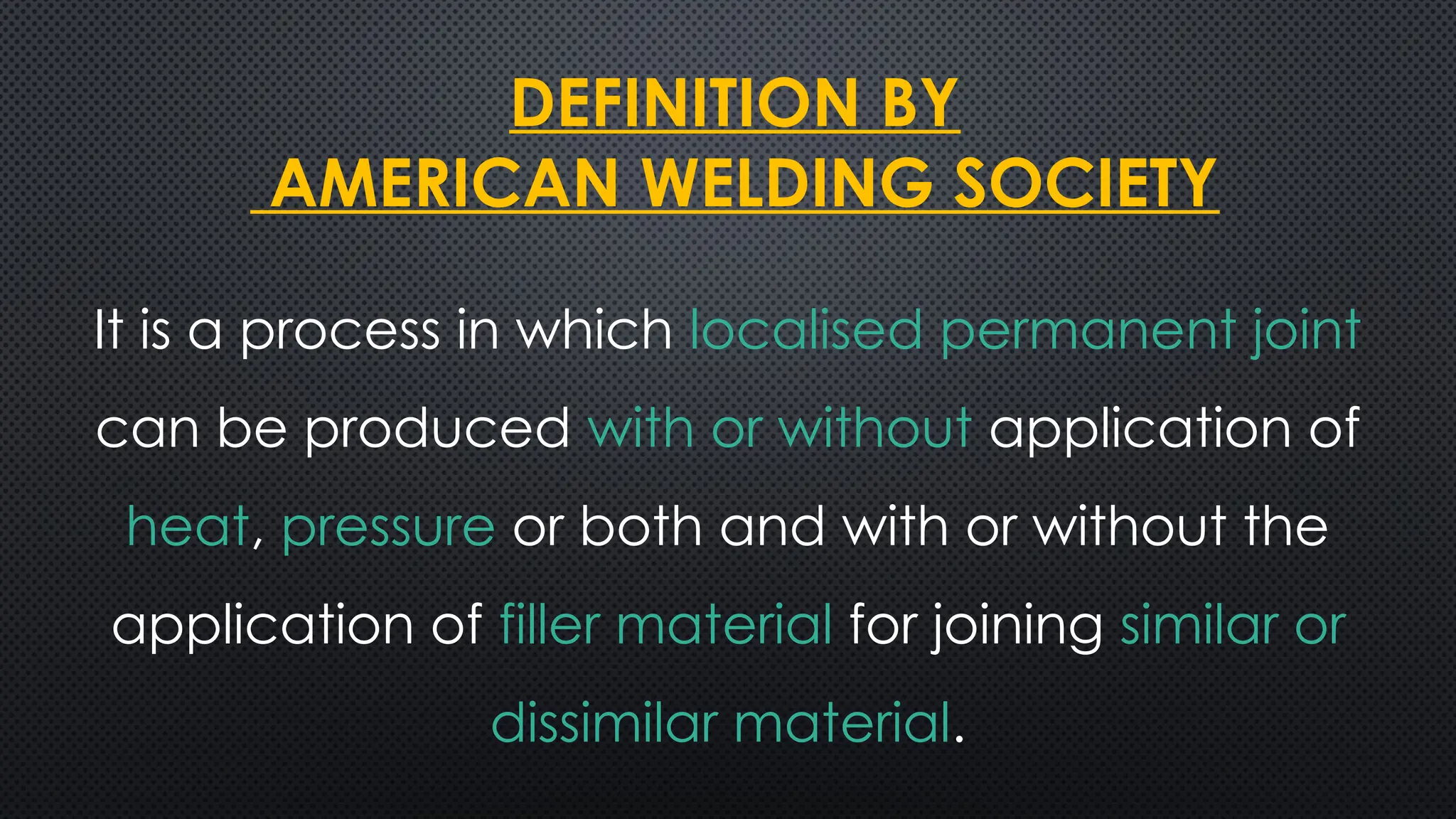
It is aprocess in which localised permanent joint
can be produced with or without application of
heat, pressure or both and with or without the
application of filler material for joining similar or
dissimilar material.
DEFINITION BY
AMERICAN WELDING SOCIETY
3.
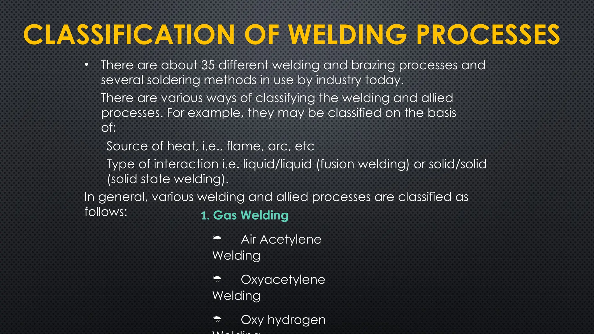
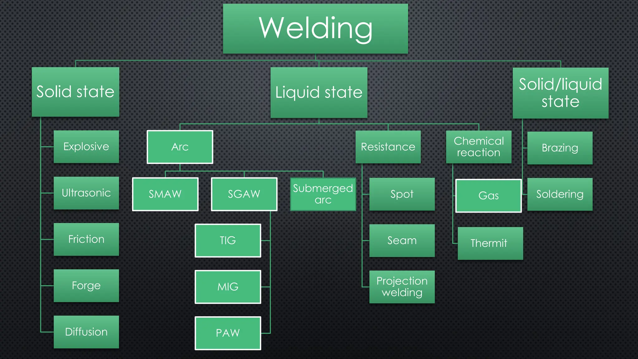
CLASSIFICATION OF WELDINGPROCESSES
• There are about 35 different welding and brazing processes and
several soldering methods in use by industry today.
There are various ways of classifying the welding and allied
processes. For example, they may be classified on the basis
of:
Source of heat, i.e., flame, arc, etc
Type of interaction i.e. liquid/liquid (fusion welding) or solid/solid
(solid state welding).
In general, various welding and allied processes are classified as
follows: 1. Gas Welding
Air Acetylene
Welding
Oxyacetylene
Welding
Oxy hydrogen
Solid state (autogenous)
Here,no filler material is added
Base metal will be in solid form
Liquid state (Homogenous)
Before joining the state of material will be liquid form
Homogeneous joint formation between filler and base material
8.
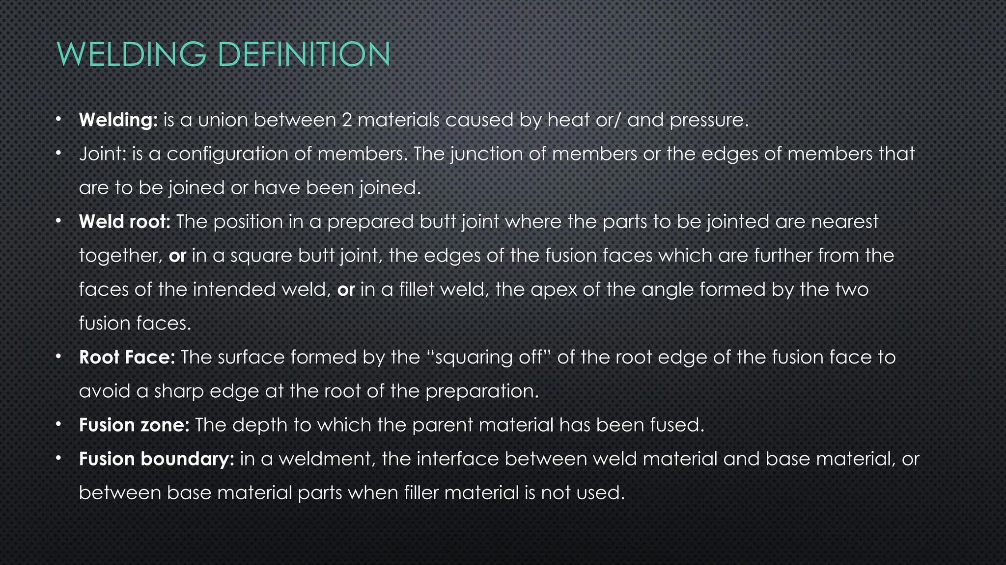
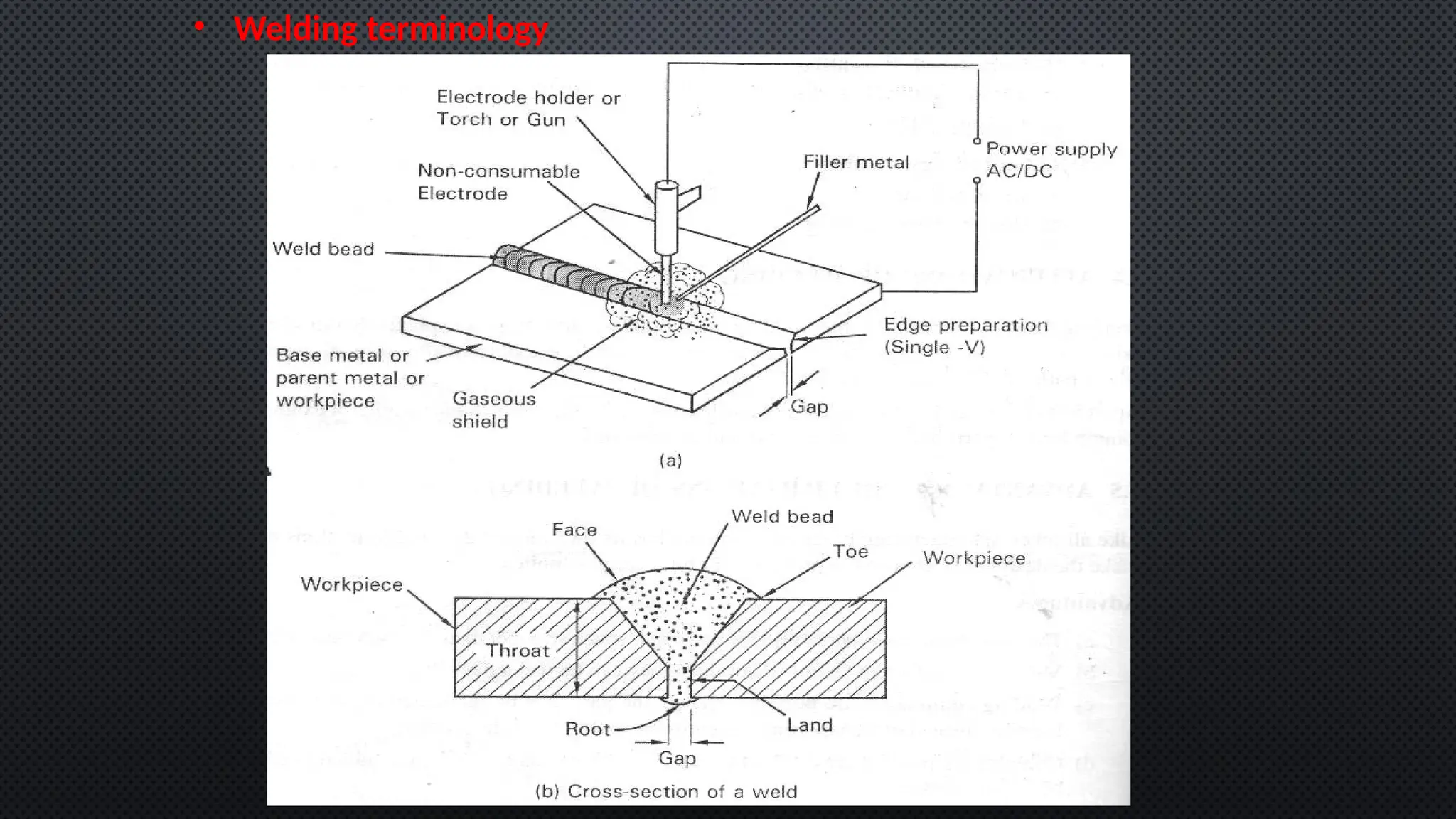
WELDING DEFINITION
• Welding:is a union between 2 materials caused by heat or/ and pressure.
• Joint: is a configuration of members. The junction of members or the edges of members that
are to be joined or have been joined.
• Weld root: The position in a prepared butt joint where the parts to be jointed are nearest
together, or in a square butt joint, the edges of the fusion faces which are further from the
faces of the intended weld, or in a fillet weld, the apex of the angle formed by the two
fusion faces.
• Root Face: The surface formed by the “squaring off” of the root edge of the fusion face to
avoid a sharp edge at the root of the preparation.
• Fusion zone: The depth to which the parent material has been fused.
• Fusion boundary: in a weldment, the interface between weld material and base material, or
between base material parts when filler material is not used.
9.
• Heat AffectedZone (HAZ): The part of the parent material where the properties have
been changed by the heat of welding or cutting, but not melted.
• Weld Face: The surface of a weld seen from the side from which the weld was made.
• Single V is the most common one 90% used for pipes and tubes.
• Double V is the second common one used for plates or heavy walls.
• Convex is the most common type of fillet used for pipe supports and structure work.
• Spot: most common in resisting used in sheet material and electrical panels.
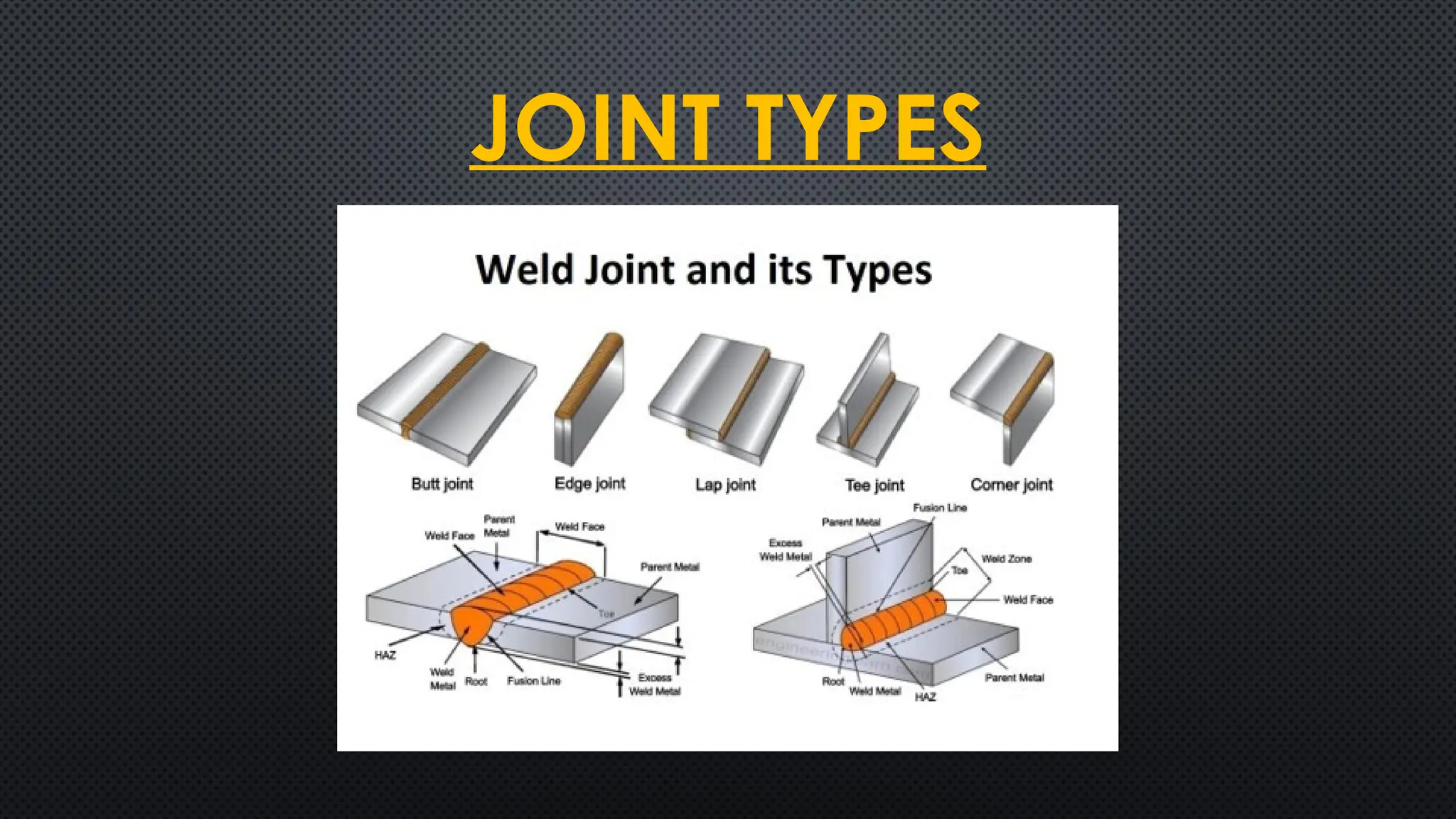
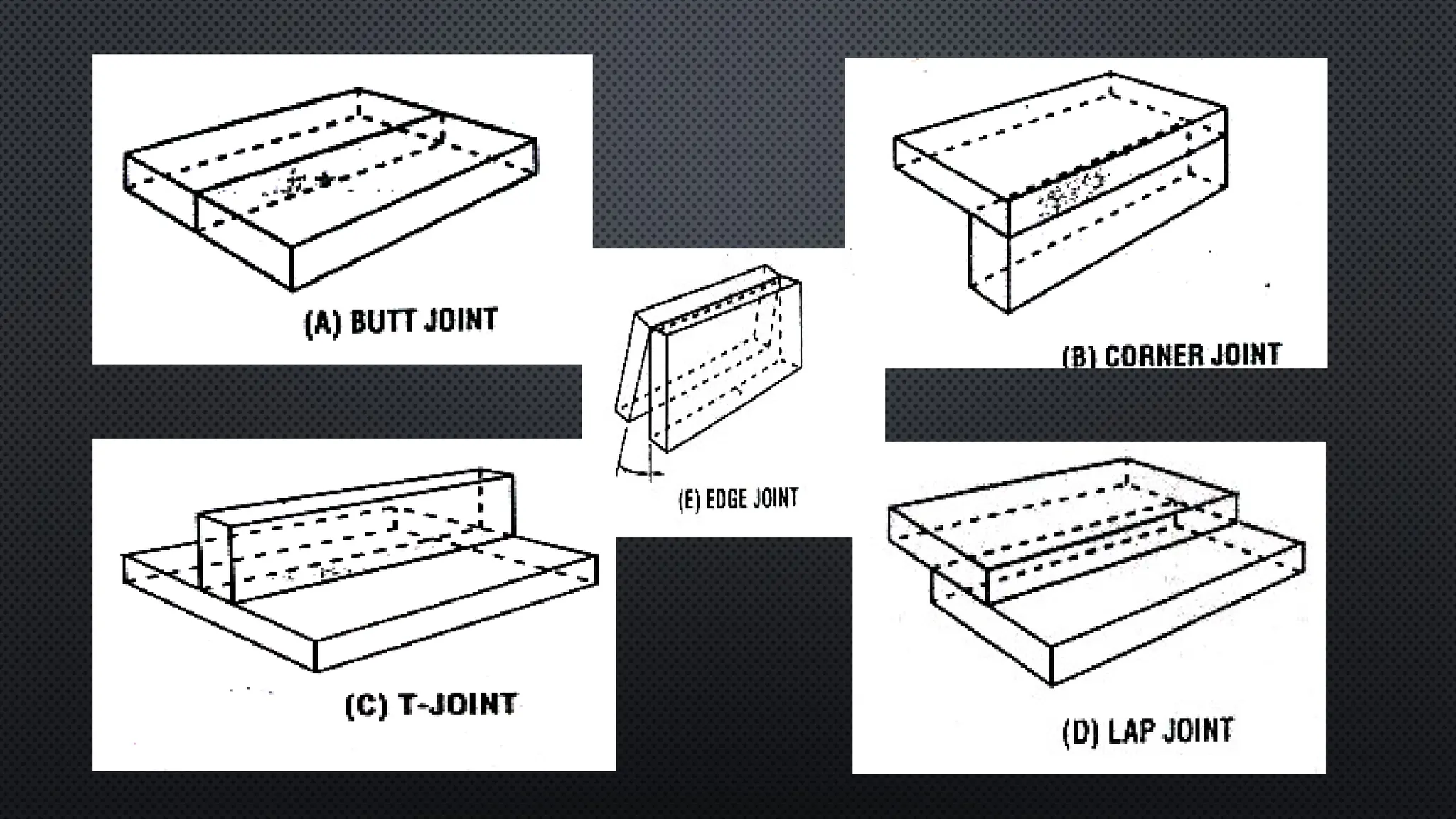
JOINT TYPES:
• SELECTIONAND PREPARATION OF WELD JOINTS IS AND IMPORTANT STEP IN
THE FABRICATION OF A WELDMENT AND IS VERY ESSENTIAL IF THE WELDED
MEMBERS ARE TO PERFORM WITHIN THE LOAD SERVICE, CORROSIVE
ATMOSPHERE AND SAFETY REQUIREMENTS.
• THE FINAL PRODUCT SHOULD HAVE SUFFICIENT STRENGTH TO PERFORM WELL
UNDER LOADED CONDITIONS AND SHOULD ALSO BE PLEASING IN
APPEARANCE.
13.
The selection ofWeld-Joint for a particular type of weldment depends upon
the following factors:-
• Base-plate thickness.
• Geometry of structure.
• Magnitude and type of loading.
• Cost of edge preparation.
• Number of passes.
• Electrode consumption and cost of welding.
• Chances and magnitude of distortion.
• Operational ease.
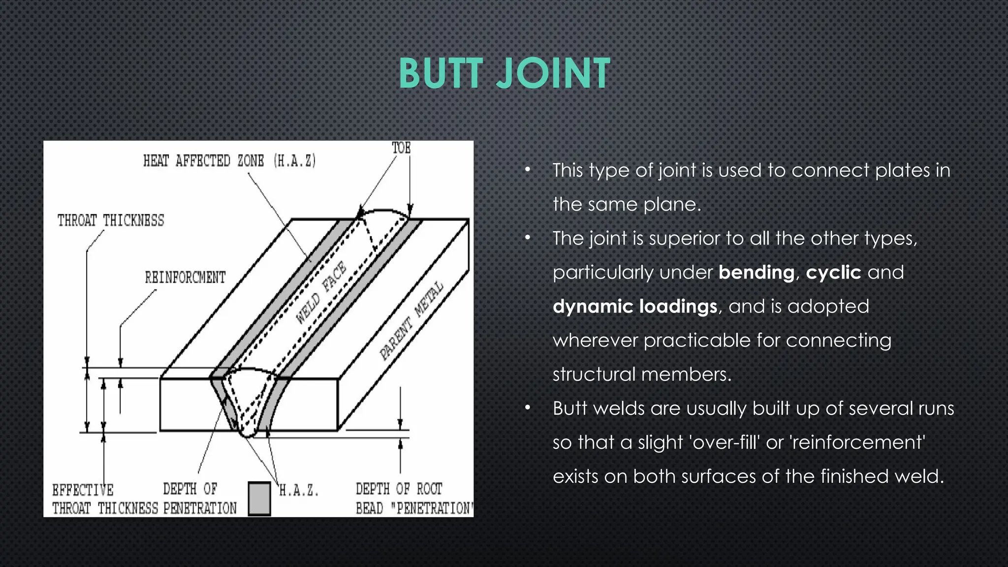
BUTT JOINT
• Thistype of joint is used to connect plates in
the same plane.
• The joint is superior to all the other types,
particularly under bending, cyclic and
dynamic loadings, and is adopted
wherever practi
cable for connecting
structural members.
• Butt welds are usually built up of several runs
so that a slight 'over-fill' or 'reinforcement'
exists on both surfaces of the finished weld.
17.
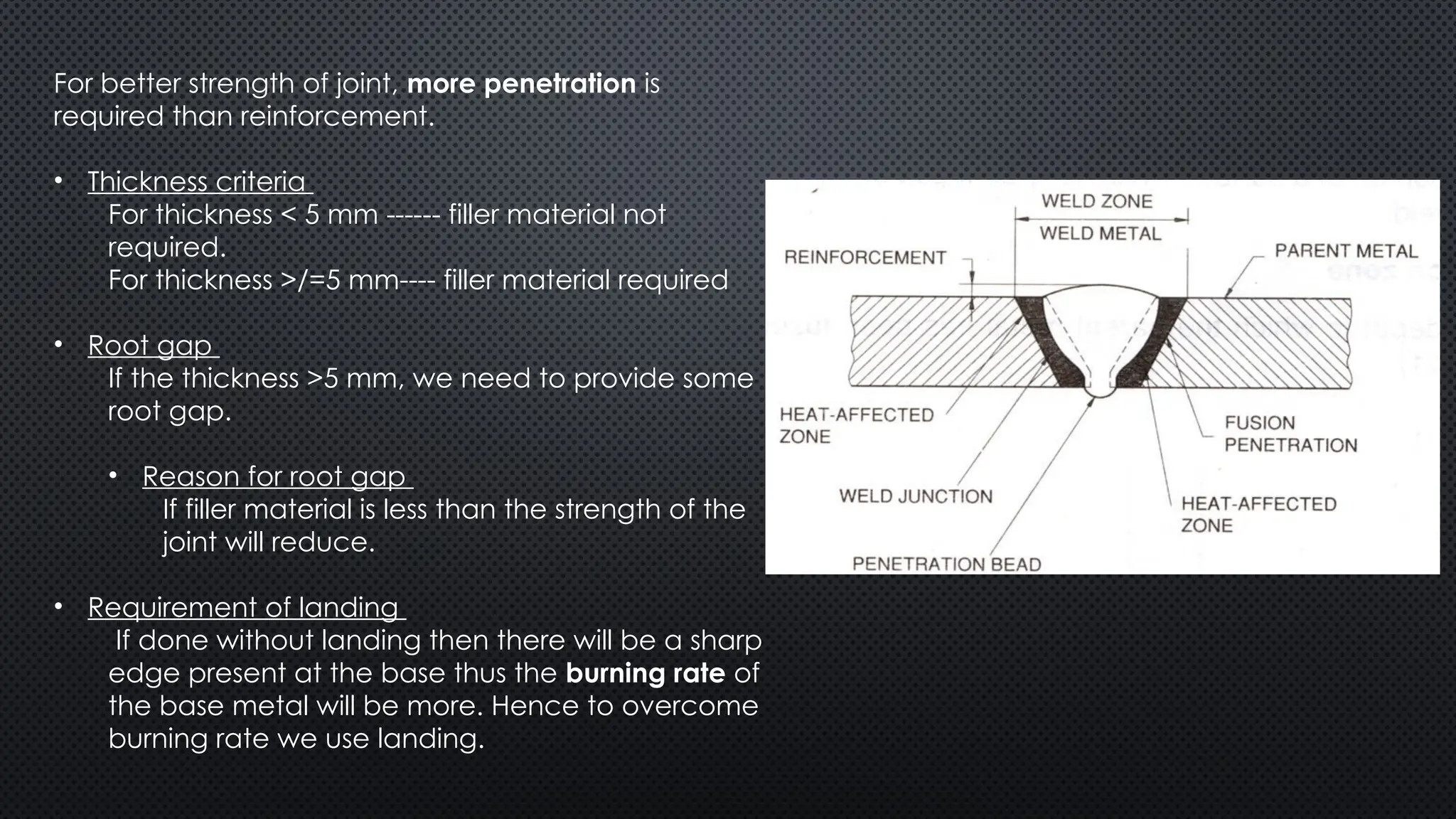
For better strengthof joint, more penetration is
required than reinforcement.
• Thickness criteria
For thickness < 5 mm ------ filler material not
required.
For thickness >/=5 mm---- filler material required
• Root gap
If the thickness >5 mm, we need to provide some
root gap.
• Reason for root gap
If filler material is less than the strength of the
joint will reduce.
• Requirement of landing
If done without landing then there will be a sharp
edge present at the base thus the burning rate of
the base metal will be more. Hence to overcome
burning rate we use landing.
18.
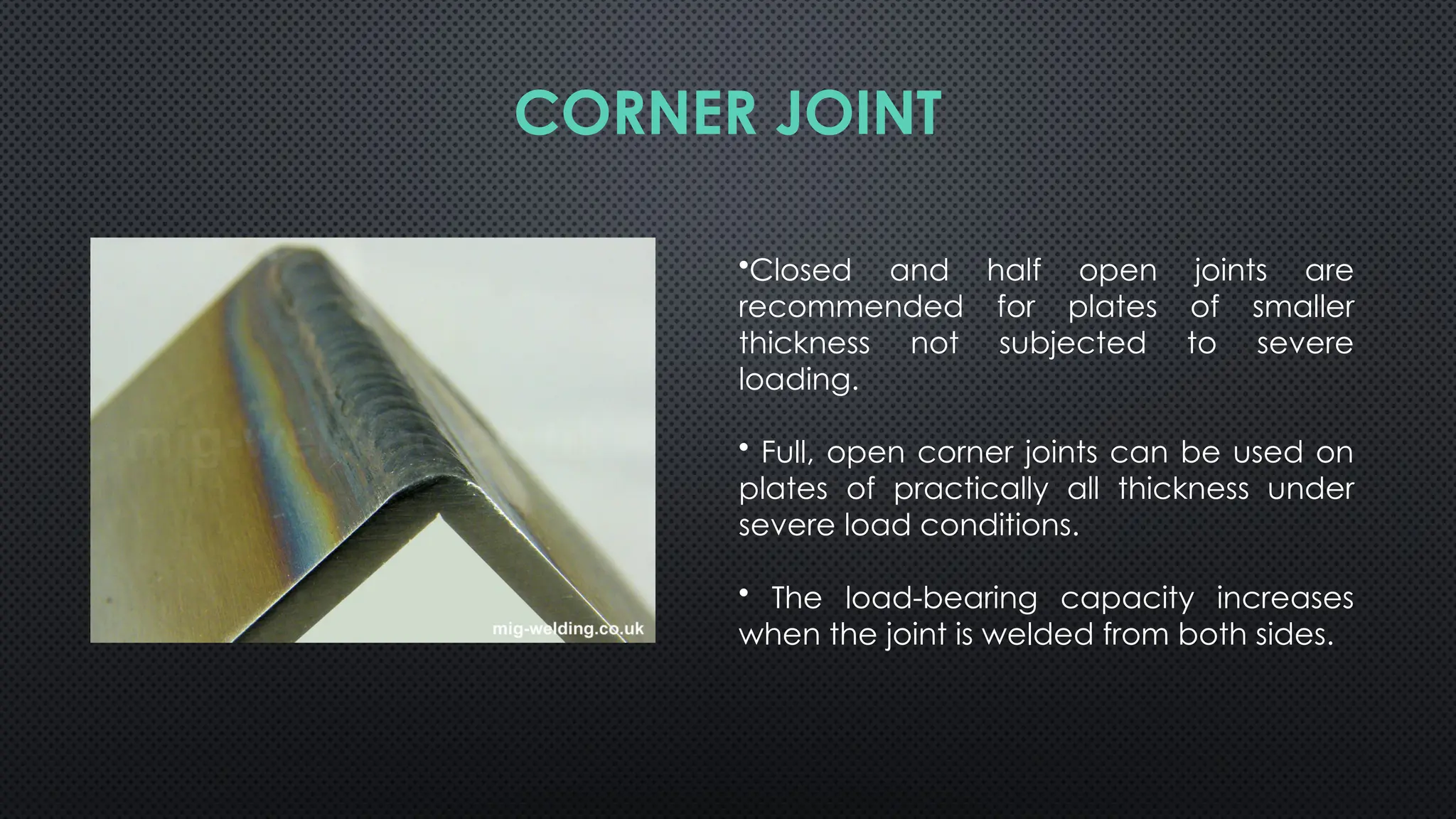
•Closed and halfopen joints are
recommended for plates of smaller
thickness not subjected to severe
loading.
• Full, open corner joints can be used on
plates of practically all thickness under
severe load conditions.
• The load-bearing capacity increases
when the joint is welded from both sides.
CORNER JOINT
19.
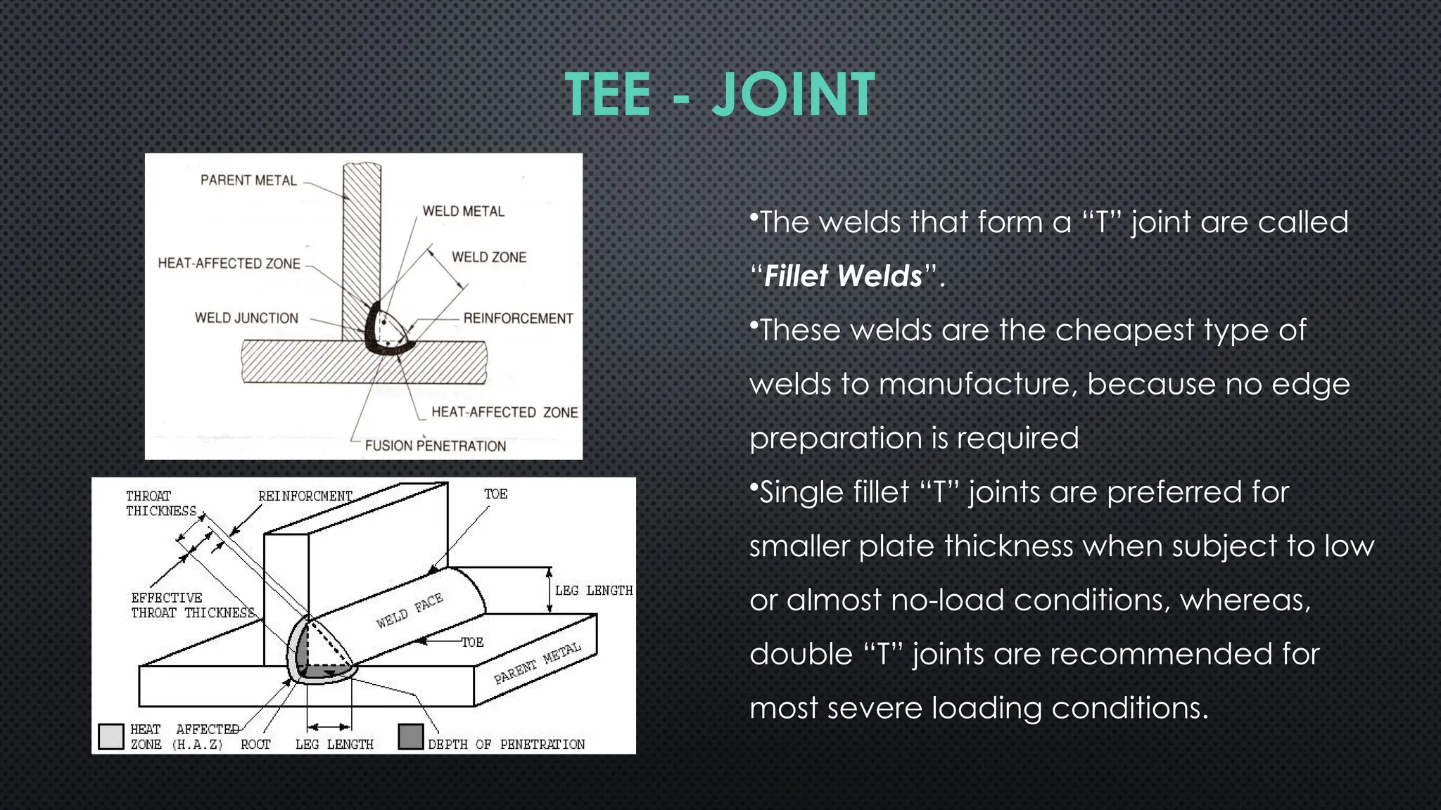
•The welds thatform a “T” joint are called
“Fillet Welds”.
•These welds are the cheapest type of
welds to manufacture, because no edge
preparation is required
•Single fillet “T” joints are preferred for
smaller plate thickness when subject to low
or almost no-load conditions, whereas,
double “T” joints are recommended for
most severe loading conditions.
TEE - JOINT
20.
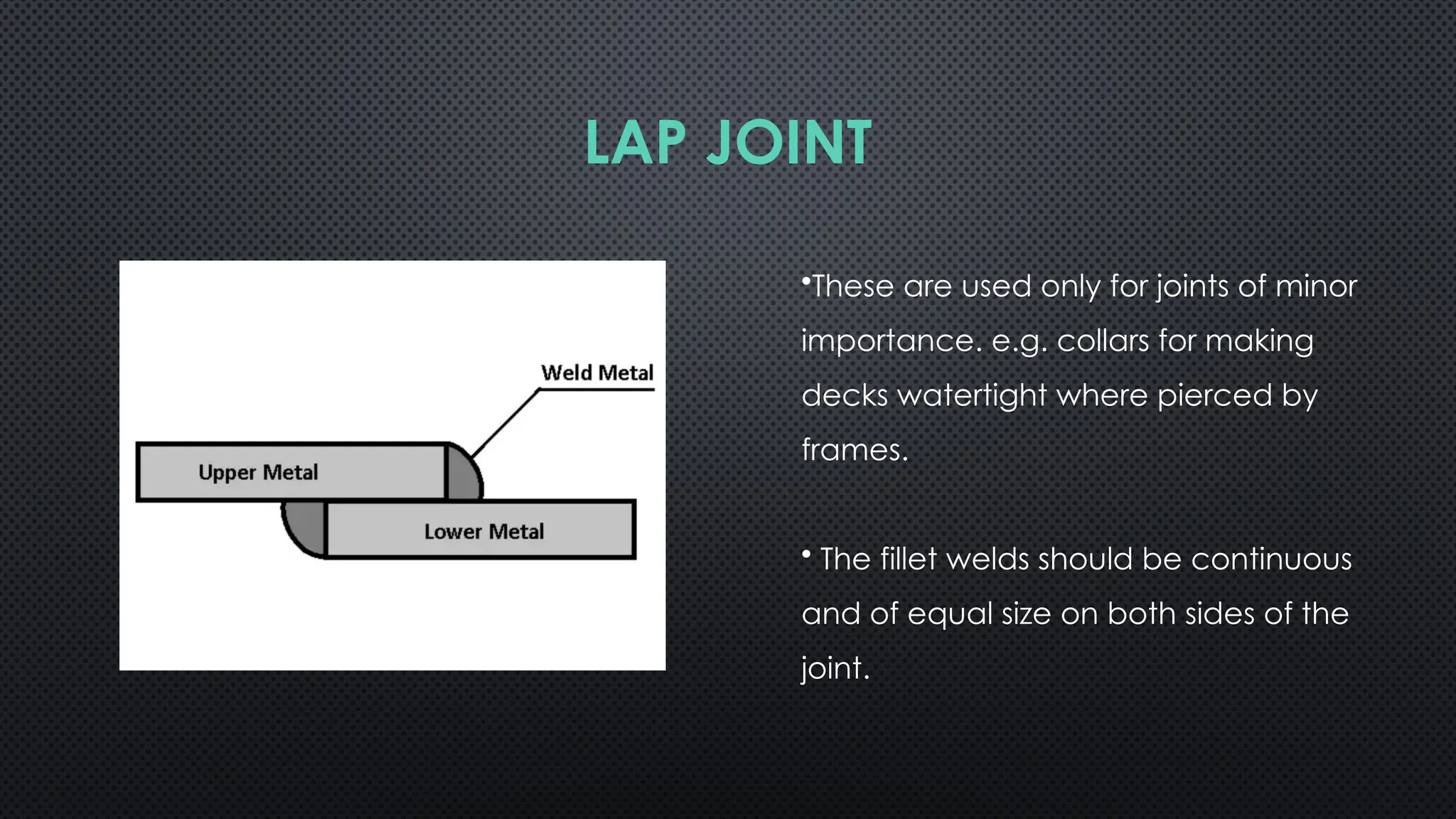
•These are usedonly for joints of minor
importance. e.g. collars for making
decks watertight where pierced by
frames.
• The fillet welds should be continuous
and of equal size on both sides of the
joint.
LAP JOINT
21.
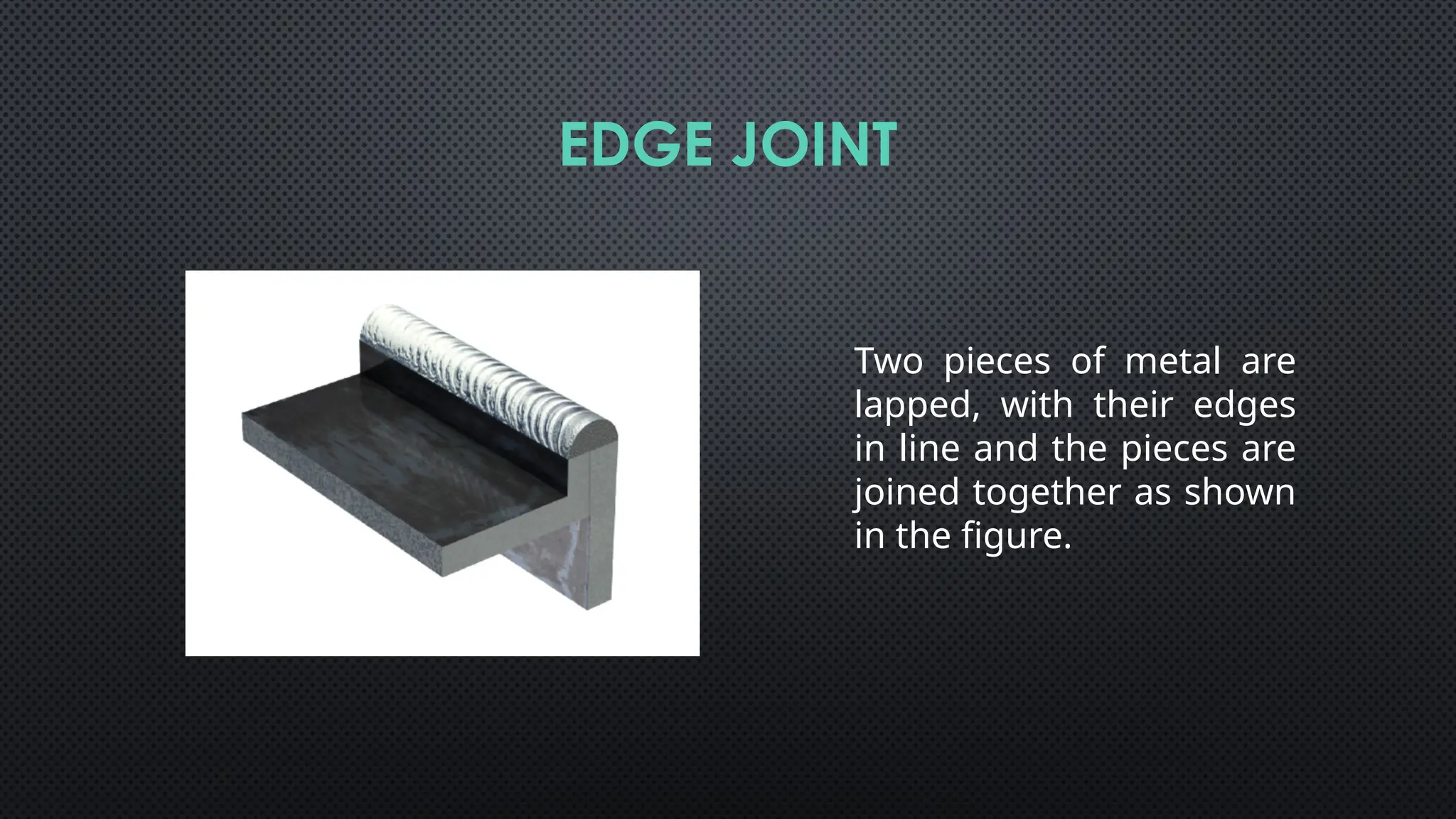
Two pieces ofmetal are
lapped, with their edges
in line and the pieces are
joined together as shown
in the figure.
EDGE JOINT
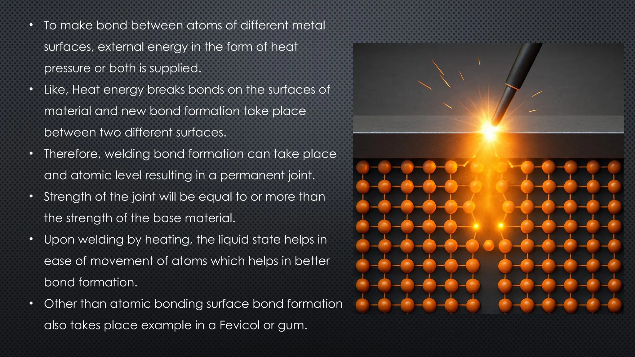
• To makebond between atoms of different metal
surfaces, external energy in the form of heat
pressure or both is supplied.
• Like, Heat energy breaks bonds on the surfaces of
material and new bond formation take place
between two different surfaces.
• Therefore, welding bond formation can take place
and atomic level resulting in a permanent joint.
• Strength of the joint will be equal to or more than
the strength of the base material.
• Upon welding by heating, the liquid state helps in
ease of movement of atoms which helps in better
bond formation.
• Other than atomic bonding surface bond formation
also takes place example in a Fevicol or gum.
30.
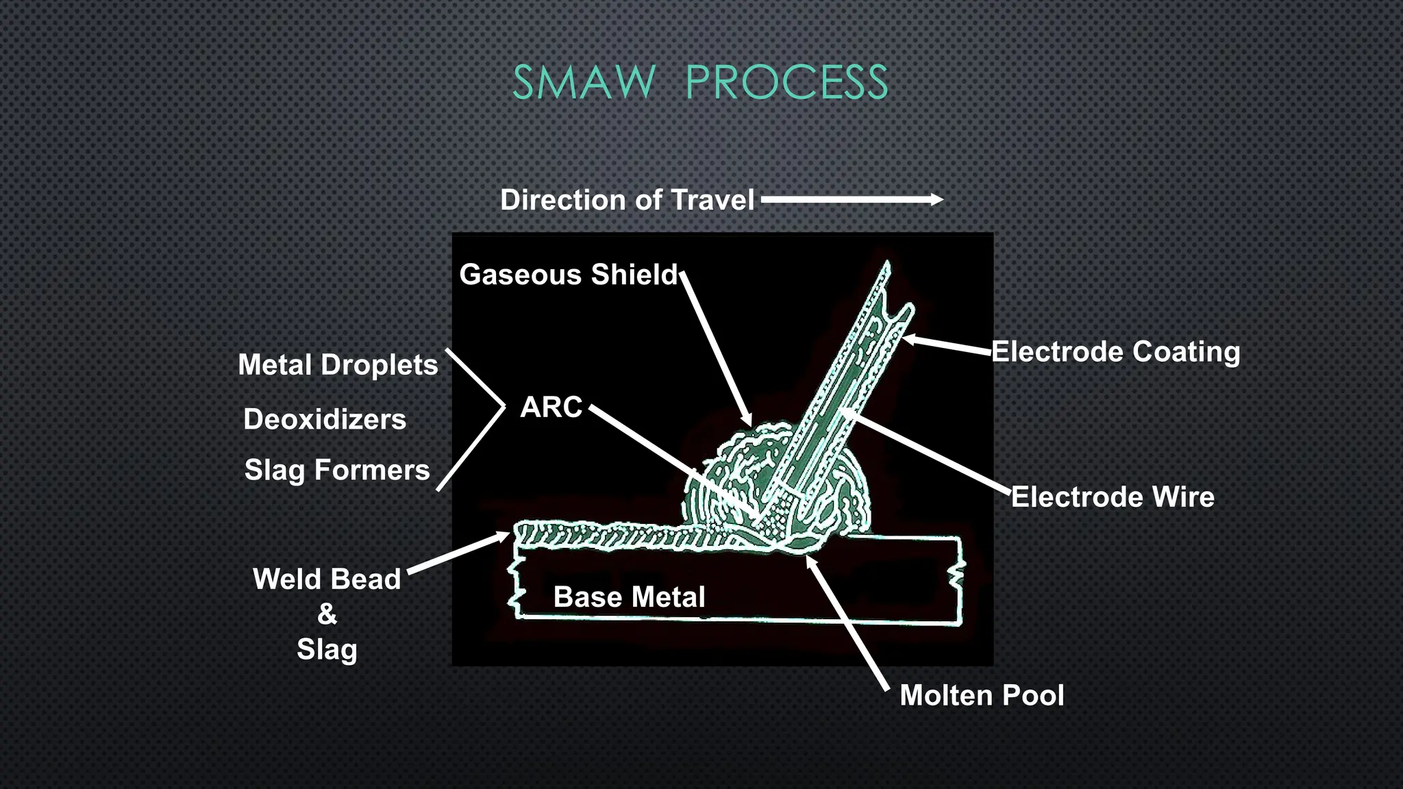
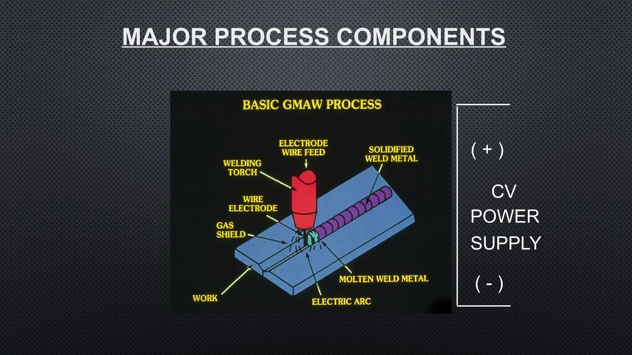
SMAW PROCESS
Base Metal
MetalDroplets
ARC
Deoxidizers
Slag Formers
Weld Bead
&
Slag
Gaseous Shield
Electrode Coating
Electrode Wire
Direction of Travel
Molten Pool
31.
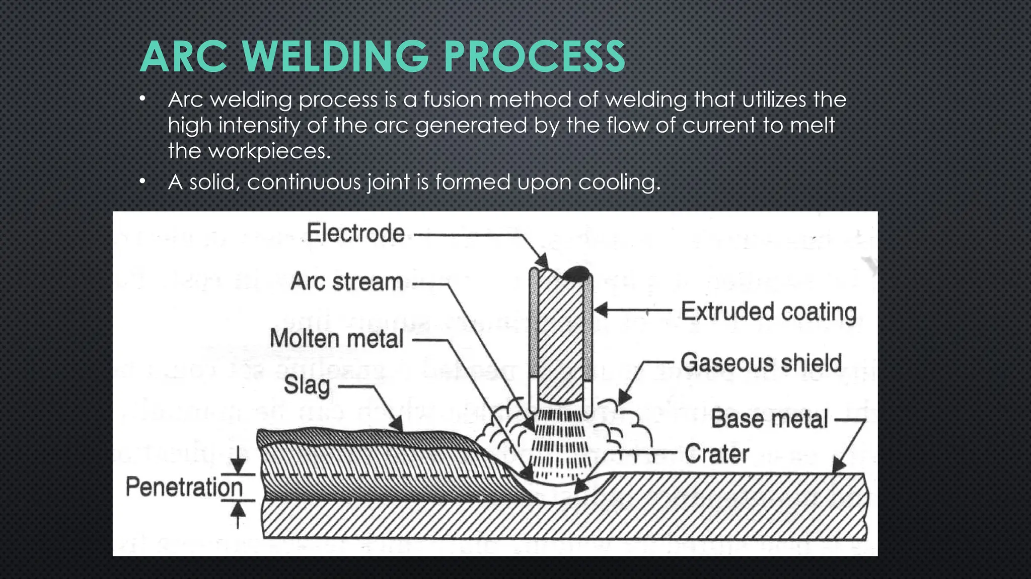
ARC WELDING PROCESS
•Arc welding process is a fusion method of welding that utilizes the
high intensity of the arc generated by the flow of current to melt
the workpieces.
• A solid, continuous joint is formed upon cooling.
32.
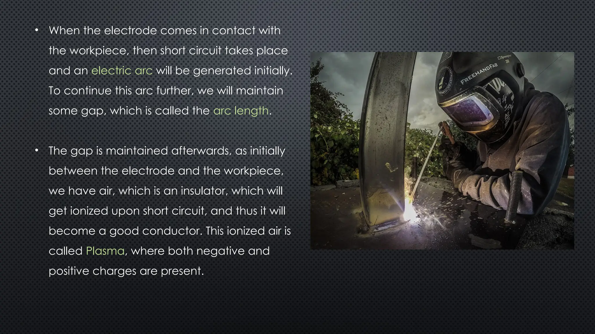
• When theelectrode comes in contact with
the workpiece, then short circuit takes place
and an electric arc will be generated initially.
To continue this arc further, we will maintain
some gap, which is called the arc length.
• The gap is maintained afterwards, as initially
between the electrode and the workpiece,
we have air, which is an insulator, which will
get ionized upon short circuit, and thus it will
become a good conductor. This ionized air is
called Plasma, where both negative and
positive charges are present.
33.
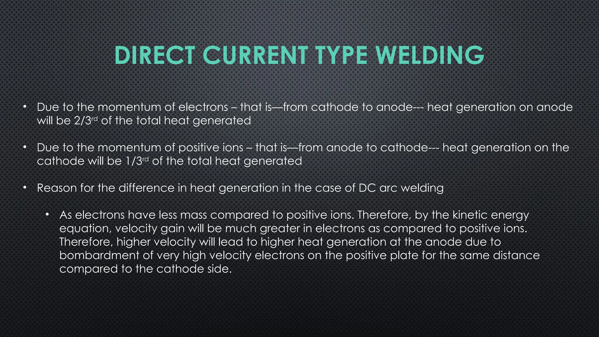
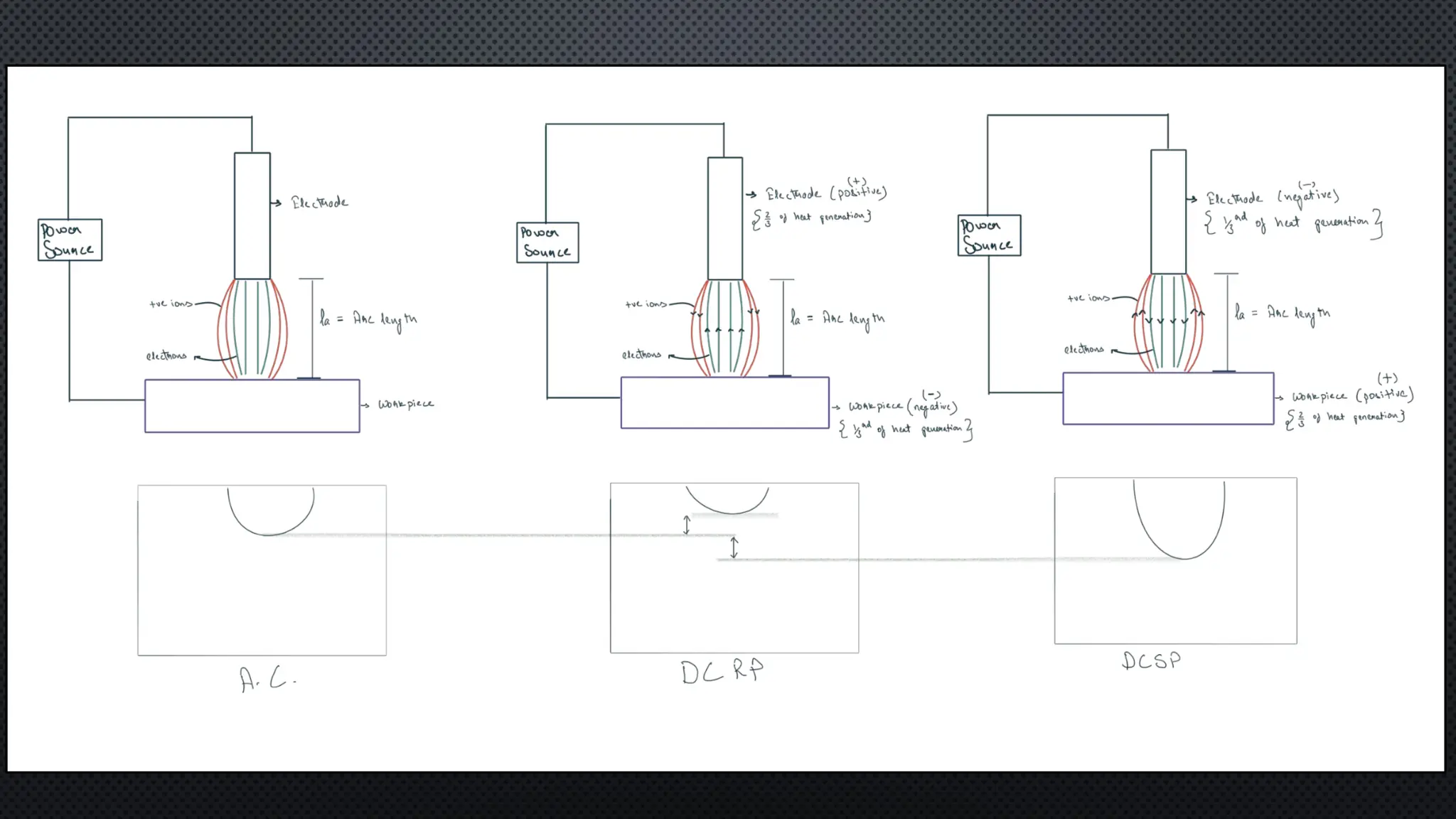
• Due tothe momentum of electrons – that is—from cathode to anode--- heat generation on anode
will be 2/3rd
of the total heat generated
• Due to the momentum of positive ions – that is—from anode to cathode--- heat generation on the
cathode will be 1/3rd
of the total heat generated
• Reason for the difference in heat generation in the case of DC arc welding
• As electrons have less mass compared to positive ions. Therefore, by the kinetic energy
equation, velocity gain will be much greater in electrons as compared to positive ions.
Therefore, higher velocity will lead to higher heat generation at the anode due to
bombardment of very high velocity electrons on the positive plate for the same distance
compared to the cathode side.
DIRECT CURRENT TYPE WELDING
34.
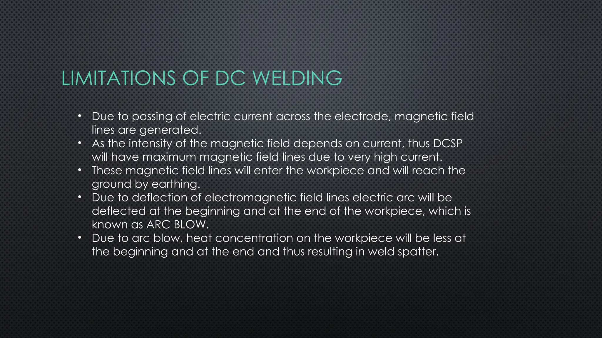
LIMITATIONS OF DCWELDING
• Due to passing of electric current across the electrode, magnetic field
lines are generated.
• As the intensity of the magnetic field depends on current, thus DCSP
will have maximum magnetic field lines due to very high current.
• These magnetic field lines will enter the workpiece and will reach the
ground by earthing.
• Due to deflection of electromagnetic field lines electric arc will be
deflected at the beginning and at the end of the workpiece, which is
known as ARC BLOW.
• Due to arc blow, heat concentration on the workpiece will be less at
the beginning and at the end and thus resulting in weld spatter.
35.
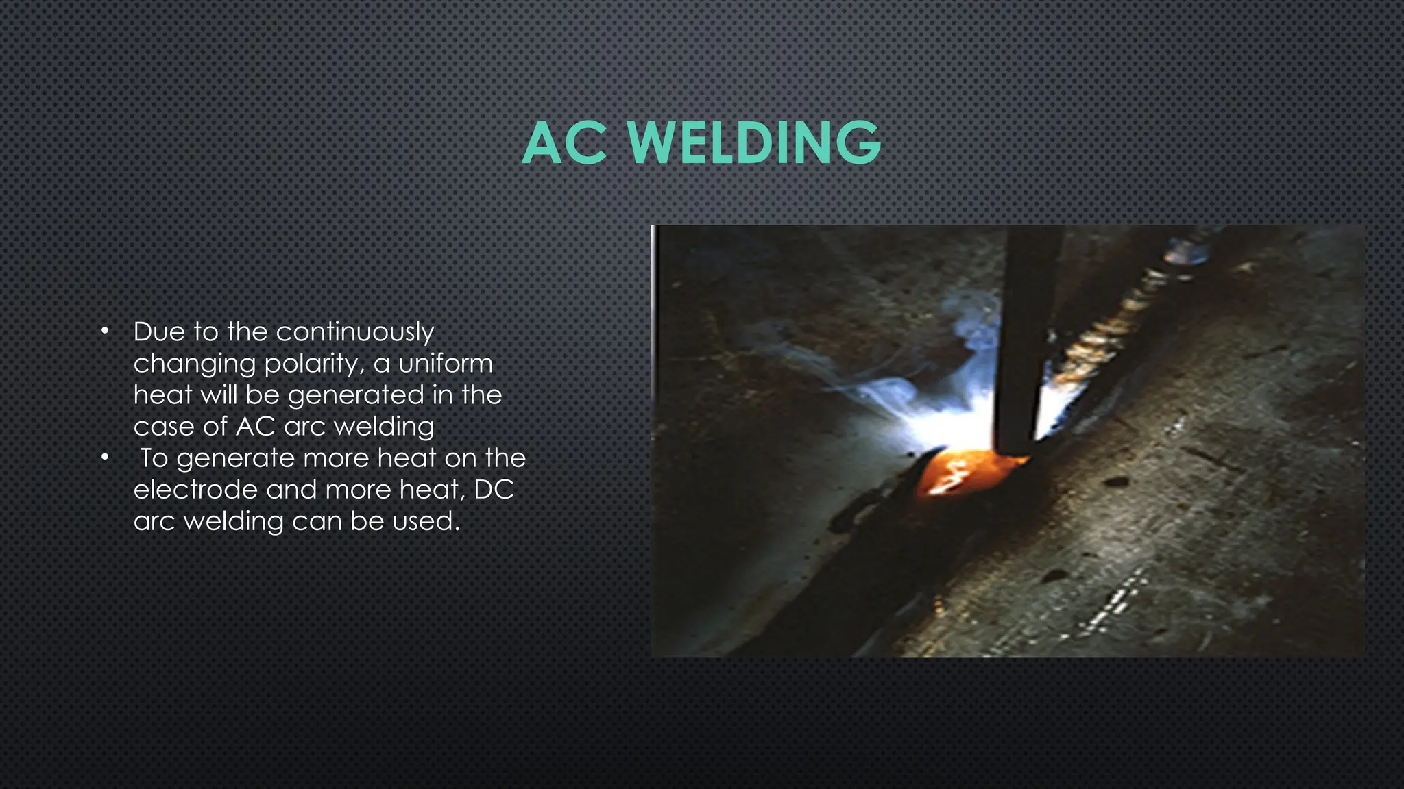
• Due tothe continuously
changing polarity, a uniform
heat will be generated in the
case of AC arc welding
• To generate more heat on the
electrode and more heat, DC
arc welding can be used.
AC WELDING
37.
La = arclength
= (0.5 to 1.1)d
Where,
d = diameter of electrode
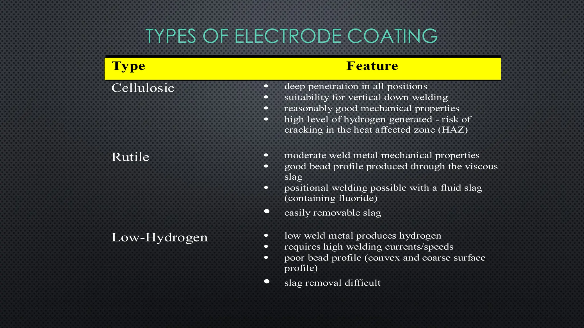
TYPES OF ELECTRODECOATING
Type Feature
Cellulosic deep penetration in all positions
suitability for vertical down welding
reasonably good mechanical properties
high level of hydrogen generated - risk of
cracking in the heat affected zone (HAZ)
Rutile moderate weld metal mechanical properties
good bead profile produced through the viscous
slag
positional welding possible with a fluid slag
(containing fluoride)
easily removable slag
Low-Hydrogen low weld metal produces hydrogen
requires high welding currents/speeds
poor bead profile (convex and coarse surface
profile)
slag removal difficult
40.
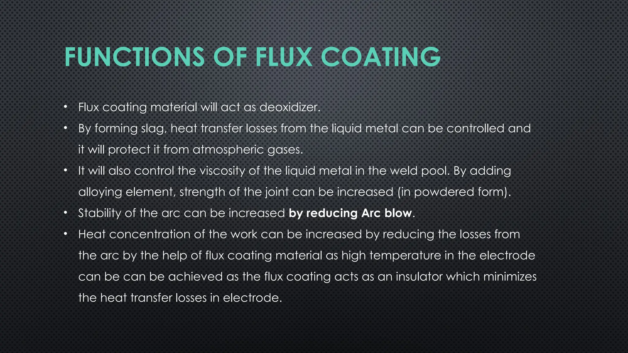
FUNCTIONS OF FLUXCOATING
• Flux coating material will act as deoxidizer.
• By forming slag, heat transfer losses from the liquid metal can be controlled and
it will protect it from atmospheric gases.
• It will also control the viscosity of the liquid metal in the weld pool. By adding
alloying element, strength of the joint can be increased (in powdered form).
• Stability of the arc can be increased by reducing Arc blow.
• Heat concentration of the work can be increased by reducing the losses from
the arc by the help of flux coating material as high temperature in the electrode
can be can be achieved as the flux coating acts as an insulator which minimizes
the heat transfer losses in electrode.
41.
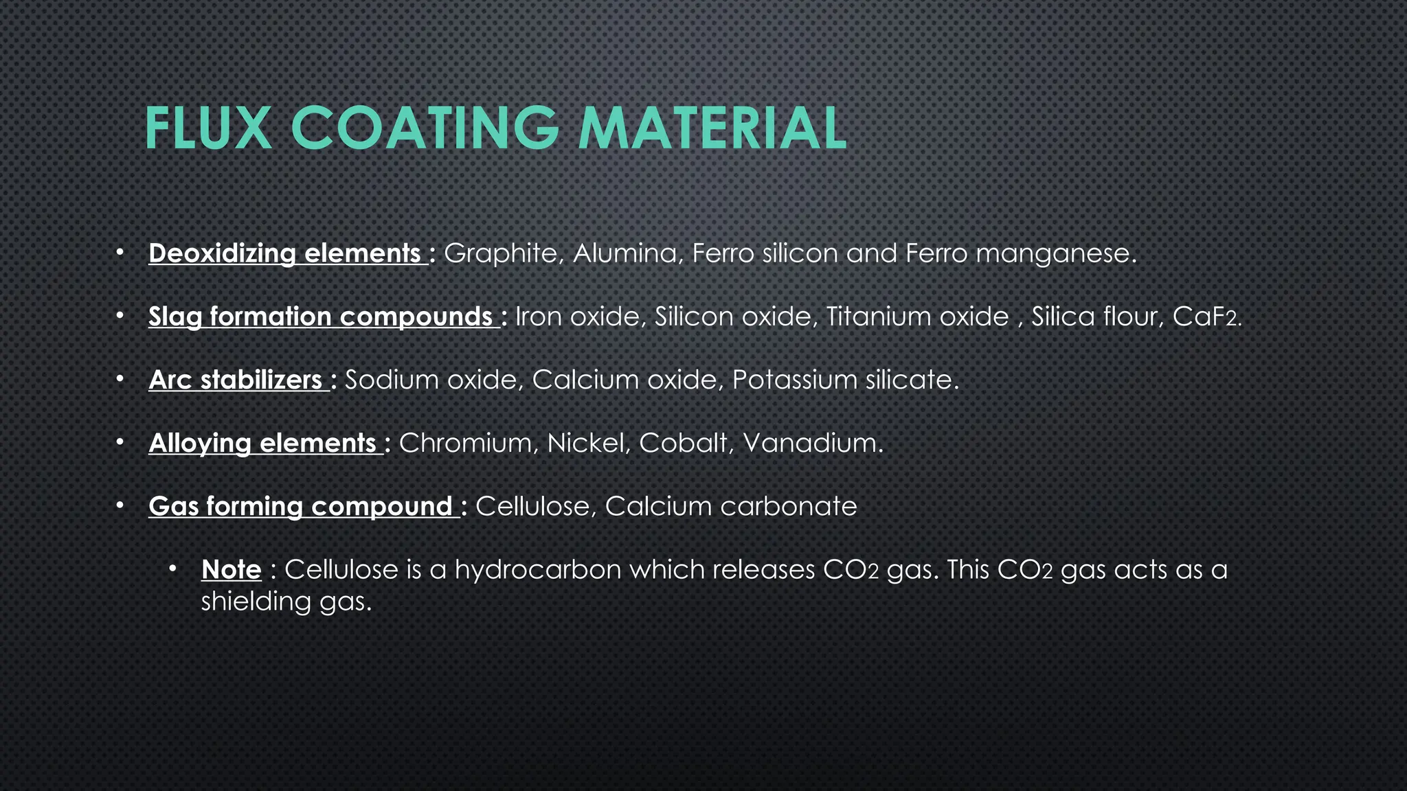
FLUX COATING MATERIAL
•Deoxidizing elements : Graphite, Alumina, Ferro silicon and Ferro manganese.
• Slag formation compounds : Iron oxide, Silicon oxide, Titanium oxide , Silica flour, CaF2.
• Arc stabilizers : Sodium oxide, Calcium oxide, Potassium silicate.
• Alloying elements : Chromium, Nickel, Cobalt, Vanadium.
• Gas forming compound : Cellulose, Calcium carbonate
• Note : Cellulose is a hydrocarbon which releases CO2 gas. This CO2 gas acts as a
shielding gas.
LIMITATIONS OF FLUXCOATING
• Slag can form on the surface of liquid metal, leading to inclusions due to the electric arc's
force.
• To prevent this, the welding torch should be tilted, which also reduces spatter.
• Flux coatings can absorb moisture, which at high temperatures dissociates into hydrogen
(H2) and oxygen (O2), potentially causing gas defects known as "damped electrodes."
• Preheating the electrodes can help mitigate this issue.
• Welding Aluminium and Magnesium alloys is challenging due to their high oxide melting
temperatures.
• When welding aluminium, the electric arc can generate Aluminium oxide (Al2O3),
which has a higher density and melting point than aluminium, causing insufficient heat
at the workpiece. To effectively weld these materials, Shielded Gas Arc Welding
(SGAW) techniques—such as Tungsten Inert Gas (TIG), Metal Inert Gas (MIG), and
plasma arc welding—are recommended.
44.
LIST OF ALLELECTRODES USED IN DIFFERENT
SECTIONS OF THE PLANT
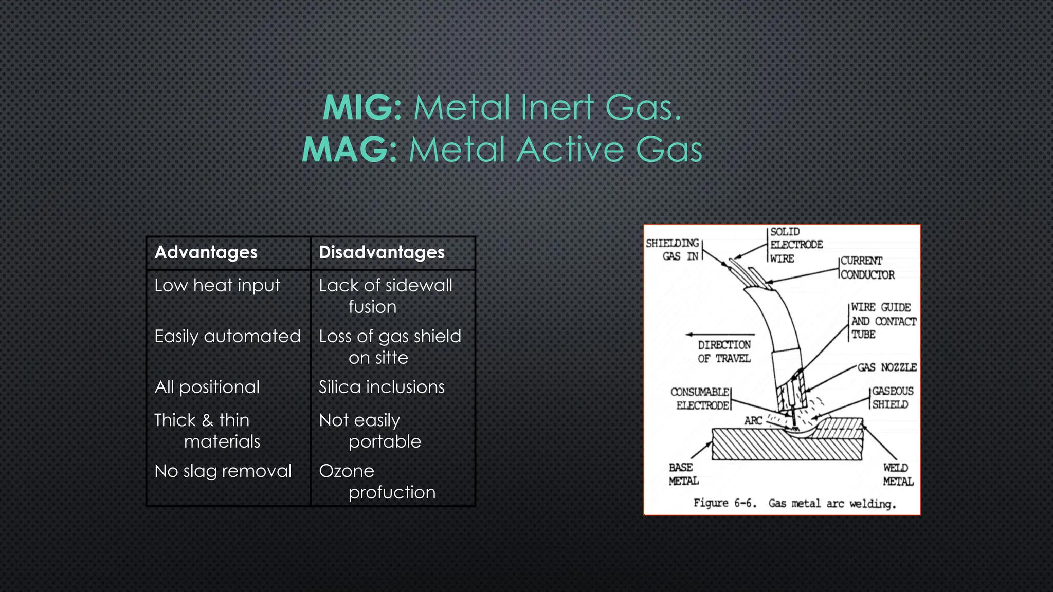
Advantages Disadvantages
Low heatinput Lack of sidewall
fusion
Easily automated Loss of gas shield
on sitte
All positional Silica inclusions
Thick & thin
materials
Not easily
portable
No slag removal Ozone
profuction
MIG: Metal Inert Gas.
MAG: Metal Active Gas
47.
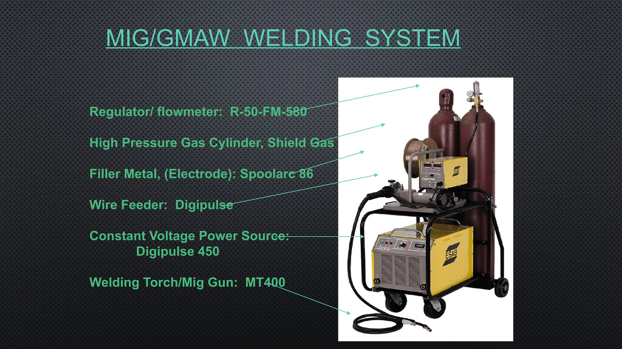
MIG/GMAW WELDING SYSTEM
Regulator/flowmeter: R-50-FM-580
High Pressure Gas Cylinder, Shield Gas
Filler Metal, (Electrode): Spoolarc 86
Wire Feeder: Digipulse
Constant Voltage Power Source:
Digipulse 450
Welding Torch/Mig Gun: MT400
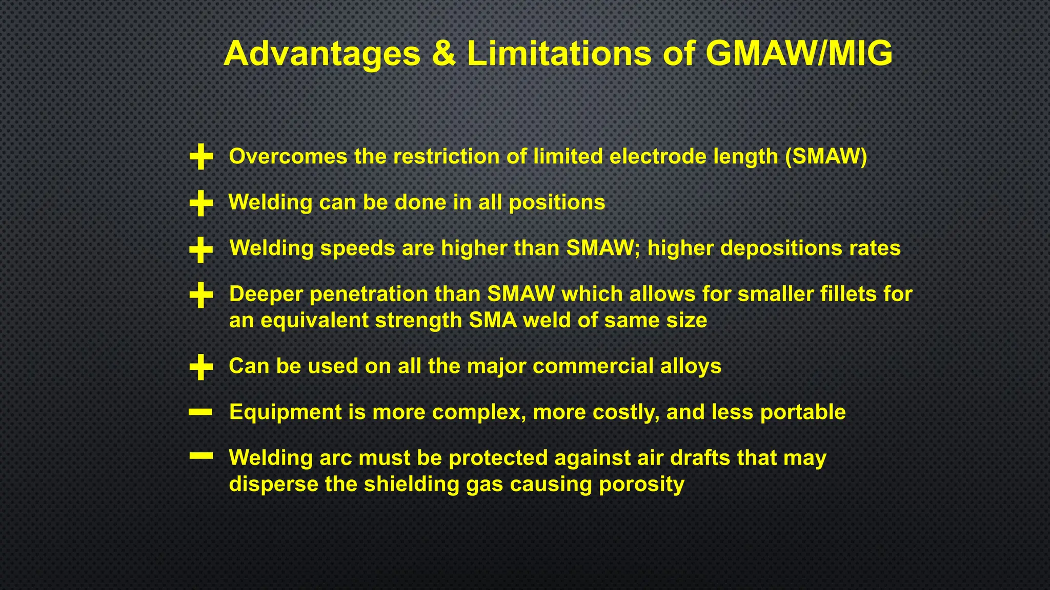
Advantages & Limitationsof GMAW/MIG
Overcomes the restriction of limited electrode length (SMAW)
Equipment is more complex, more costly, and less portable
Welding can be done in all positions
Welding speeds are higher than SMAW; higher depositions rates
Deeper penetration than SMAW which allows for smaller fillets for
an equivalent strength SMA weld of same size
Can be used on all the major commercial alloys
Welding arc must be protected against air drafts that may
disperse the shielding gas causing porosity
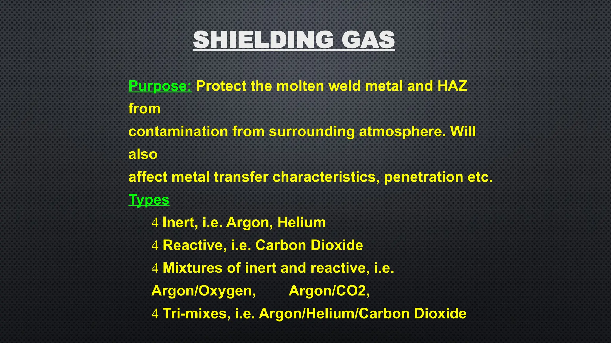
Purpose: Protect themolten weld metal and HAZ
from
contamination from surrounding atmosphere. Will
also
affect metal transfer characteristics, penetration etc.
Types
Inert, i.e. Argon, Helium
Reactive, i.e. Carbon Dioxide
Mixtures of inert and reactive, i.e.
Argon/Oxygen, Argon/CO2,
Tri-mixes, i.e. Argon/Helium/Carbon Dioxide
SHIELDING GAS
52.
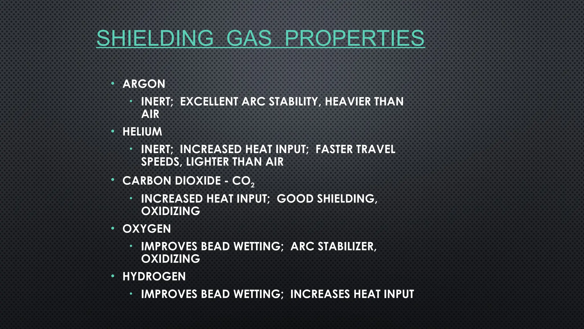
SHIELDING GAS PROPERTIES
•ARGON
• INERT; EXCELLENT ARC STABILITY, HEAVIER THAN
AIR
• HELIUM
• INERT; INCREASED HEAT INPUT; FASTER TRAVEL
SPEEDS, LIGHTER THAN AIR
• CARBON DIOXIDE - CO2
• INCREASED HEAT INPUT; GOOD SHIELDING,
OXIDIZING
• OXYGEN
• IMPROVES BEAD WETTING; ARC STABILIZER,
OXIDIZING
• HYDROGEN
• IMPROVES BEAD WETTING; INCREASES HEAT INPUT
53.
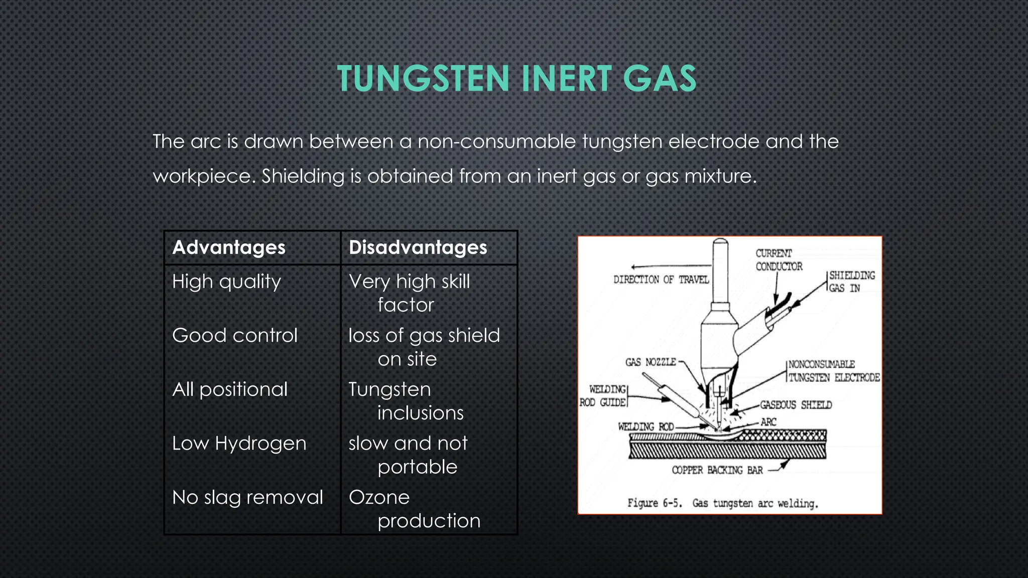
TUNGSTEN INERT GAS
Thearc is drawn between a non-consumable tungsten electrode and the
workpiece. Shielding is obtained from an inert gas or gas mixture.
Advantages Disadvantages
High quality Very high skill
factor
Good control loss of gas shield
on site
All positional Tungsten
inclusions
Low Hydrogen slow and not
portable
No slag removal Ozone
production
54.
To reduce theconsumption of non
consumable electrodes we use high
melting point electrode materials such
as tungsten, carbon, graphite
Tungsten also has high electron
emission capability
Joint can be produced without filler
material if plate thickness is less than
5mm.
If more than 5mm then filler material is
required.
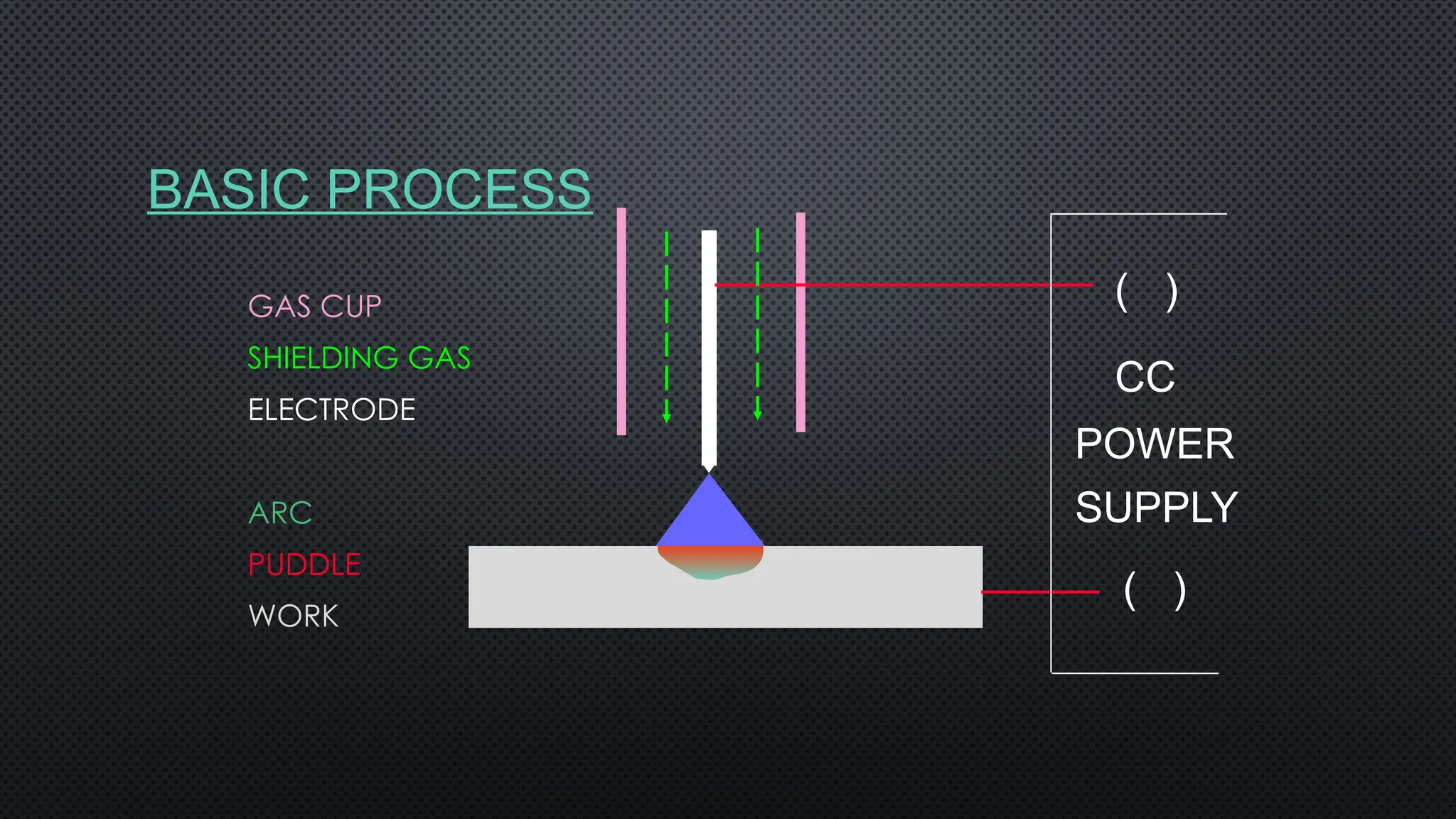
An arc is generated between the non-consumable
tungsten electrode and the workpiece
• Liquid metal in the weld pool can be protected by
providing inert gas.
• For welding, except for aluminium and magnesium
alloys, Direct Current Straight Polarity (DCSP) can be
used.
• For the welding of aluminium and magnesium alloys
A.C. power supply is used, in which the first half of the
cycle (due to straight polarity), oxide layers can be
formed on the work surface.
• In the second half of the cycle, due to reverse polarity,
oxide layers can be cleaned.
This is known as cathodic cleaning.
55.
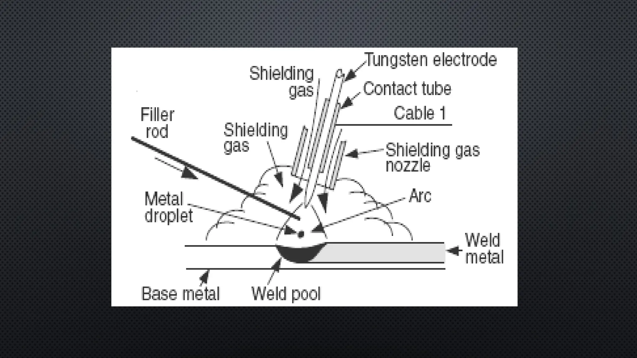
TUGSTEN INERT GASWELDING
• IT IS AN ARC WELDING PROCESS WHERE IN COALESCENCE IS PRODUCED BY
HEATING THE JOB WITH AN ELECTRIC ARC STRUCK BETWEEN A TUNGSTEN
ELECTRODE AND THE JOB.
• A SHIELDING GAS (ARGON, HELIUM, NITROGEN, ETC) IS USED TO AVOID
ATMOSPHERIC CONTAMINATION OF THE MOLTEN WELD POOL.
• A FILLER METAL MAY BE ADDED IF REQUIRED.
• IN THIS PROCESS A NON- CONSUMABLE ELECTRODE (TUNGSTEN) IS USED.
• TIG WELDING IS VERY MUCH SUITABLE FOR HIGH QUALITY WELDING OF THIN
MATERIALS AS THIN AS 0.125 MM.
57.
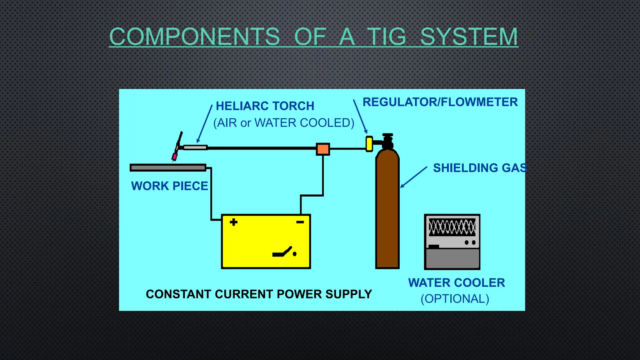
COMPONENTS OF ATIG SYSTEM
SHIELDING GAS
WATER COOLER
CONSTANT CURRENT POWER SUPPLY
WORK PIECE
HELIARC TORCH REGULATOR/FLOWMETER
(AIR or WATER COOLED)
(OPTIONAL)
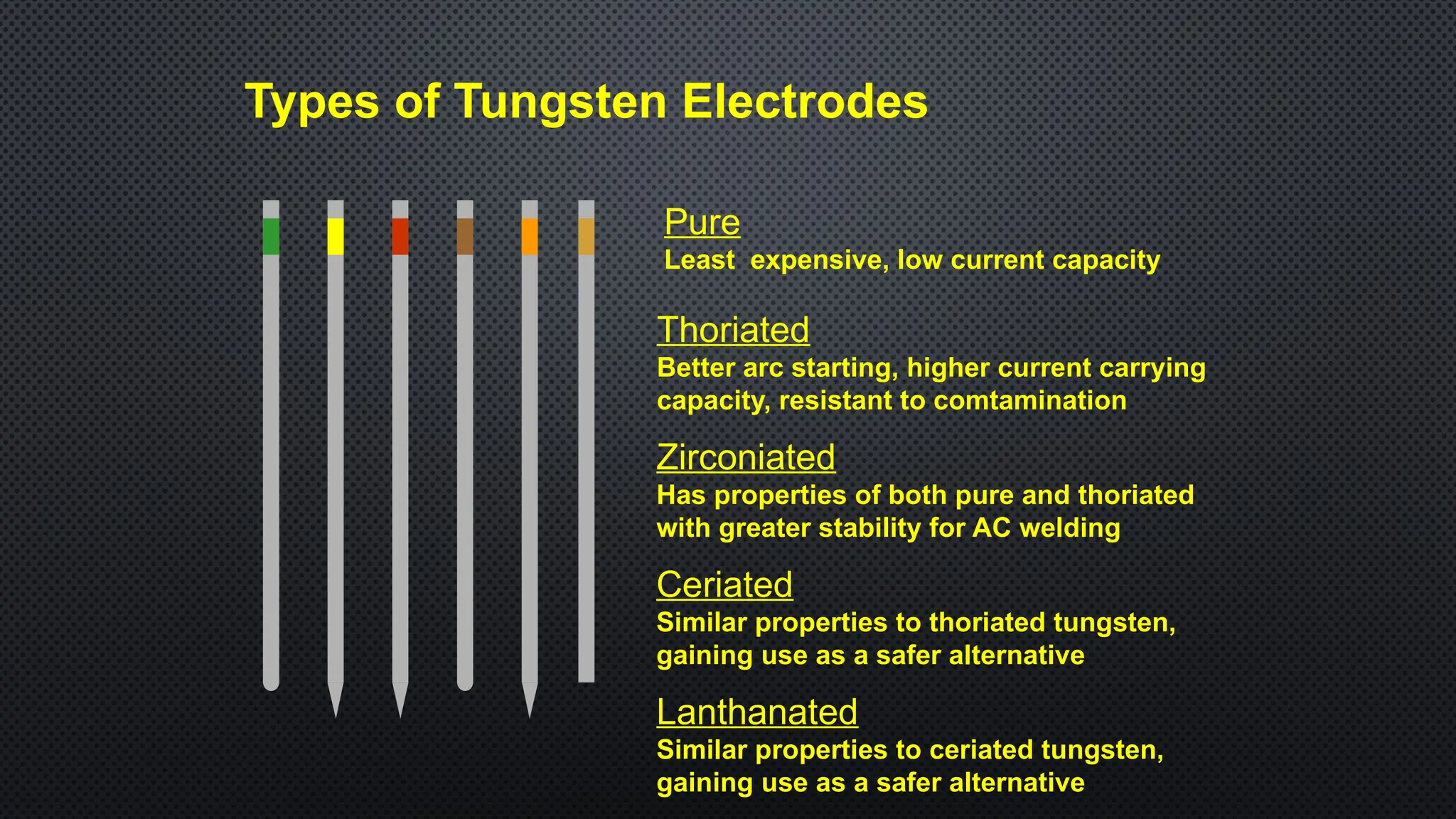
Pure
Least expensive, lowcurrent capacity
Zirconiated
Has properties of both pure and thoriated
with greater stability for AC welding
Thoriated
Better arc starting, higher current carrying
capacity, resistant to comtamination
Ceriated
Similar properties to thoriated tungsten,
gaining use as a safer alternative
Lanthanated
Similar properties to ceriated tungsten,
gaining use as a safer alternative
Types of Tungsten Electrodes
65.
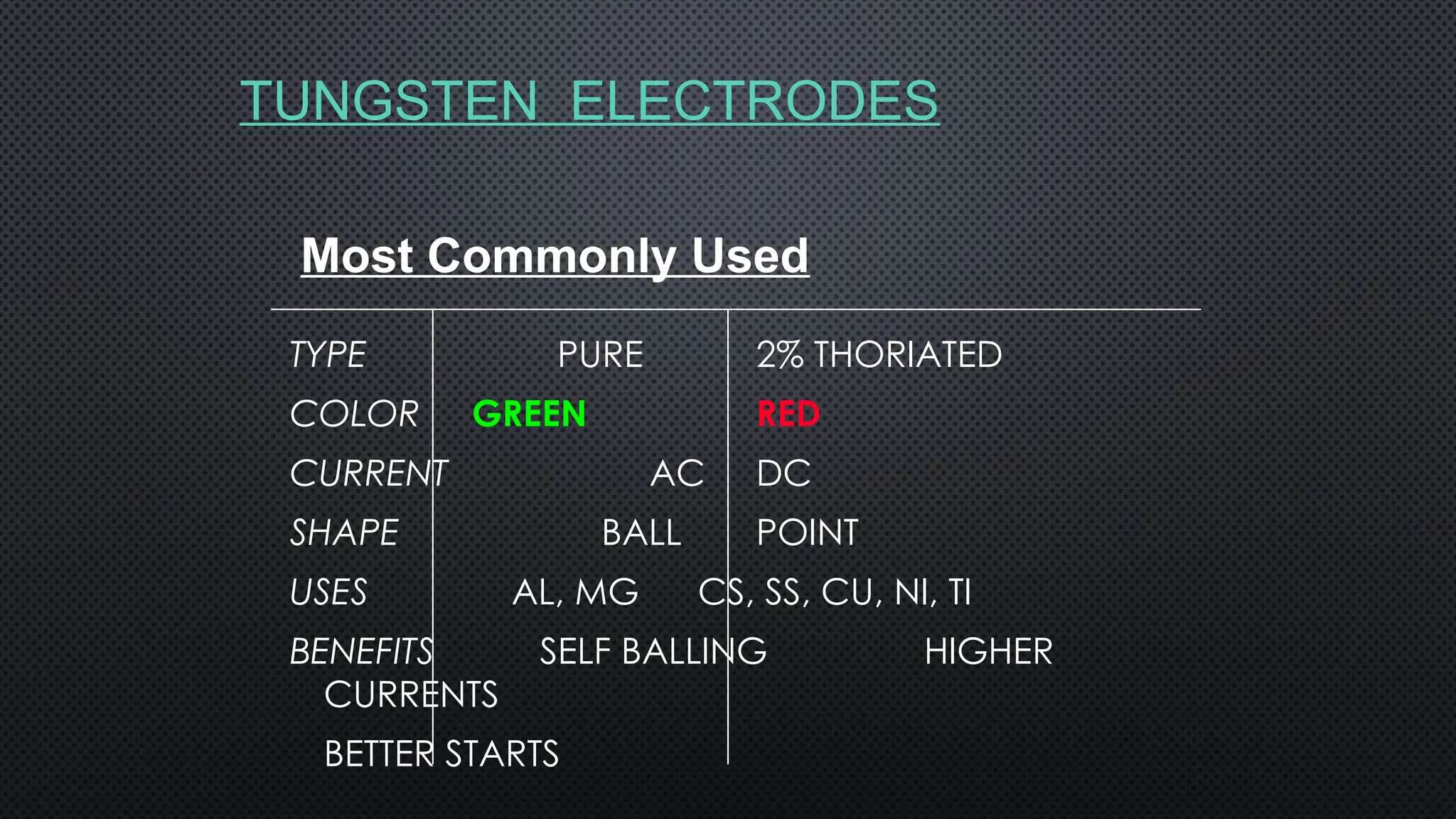
TUNGSTEN ELECTRODES
TYPE PURE2% THORIATED
COLOR GREEN RED
CURRENT AC DC
SHAPE BALL POINT
USES AL, MG CS, SS, CU, NI, TI
BENEFITS SELF BALLING HIGHER
CURRENTS
BETTER STARTS
Most Commonly Used
66.
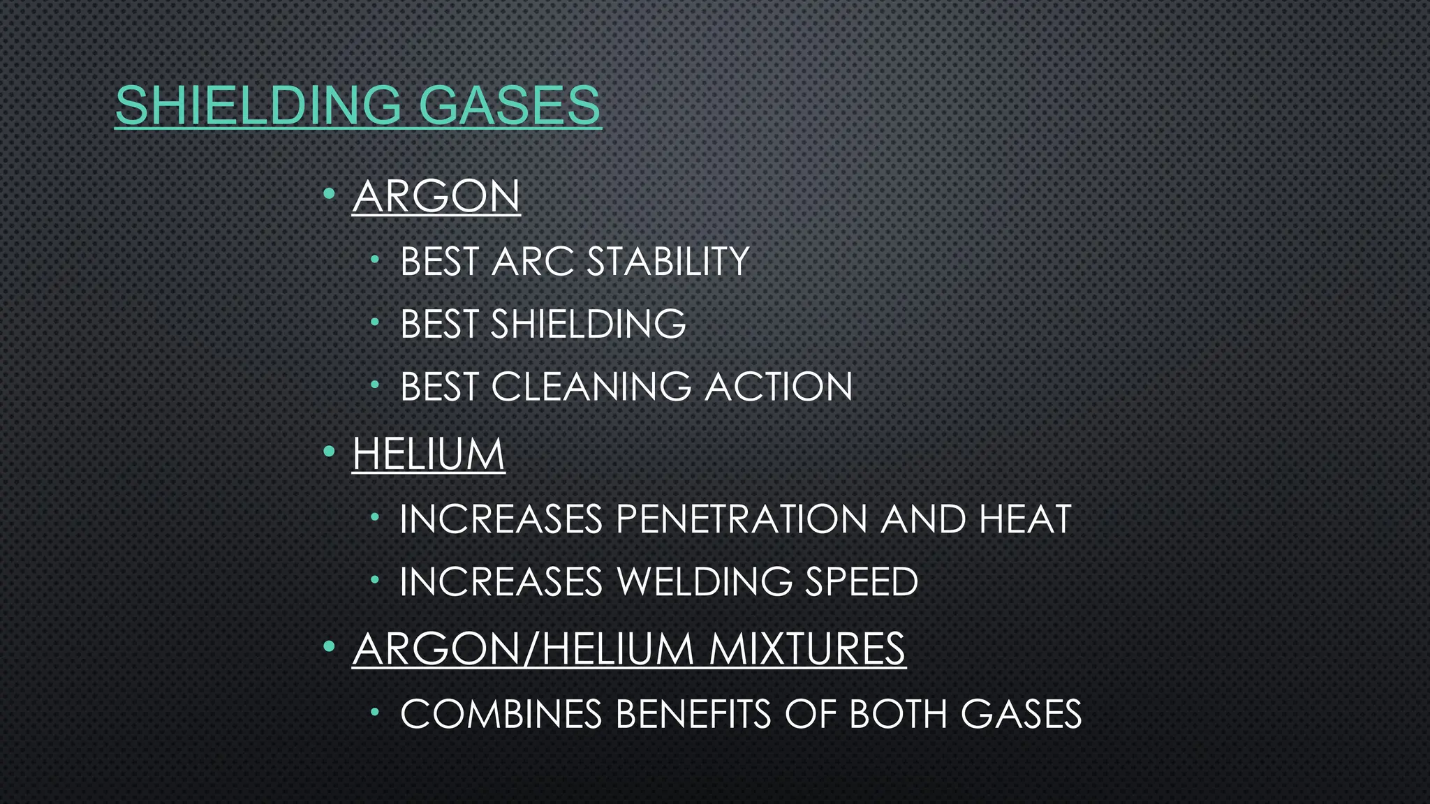
SHIELDING GASES
• ARGON
•BEST ARC STABILITY
• BEST SHIELDING
• BEST CLEANING ACTION
• HELIUM
• INCREASES PENETRATION AND HEAT
• INCREASES WELDING SPEED
• ARGON/HELIUM MIXTURES
• COMBINES BENEFITS OF BOTH GASES
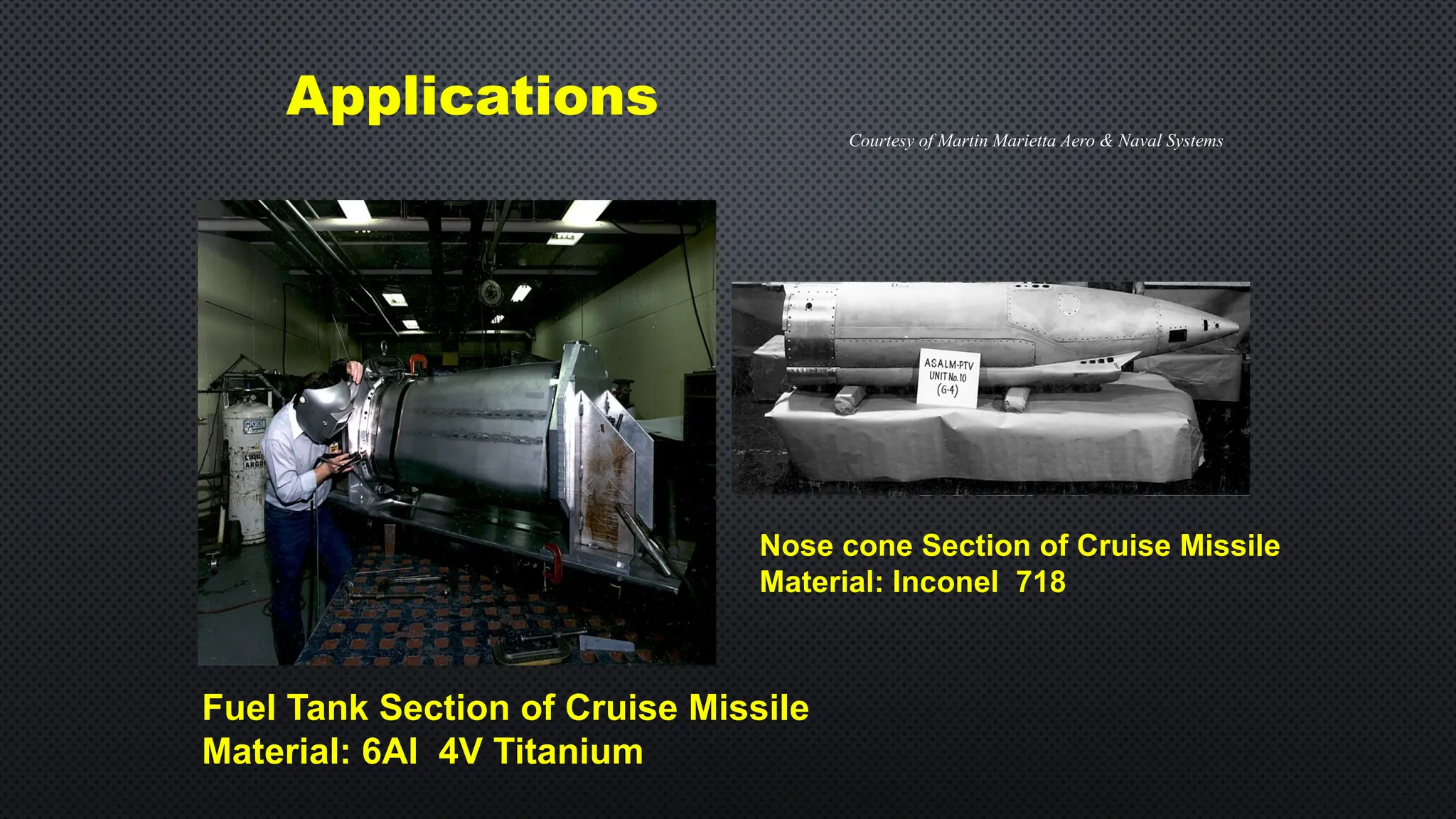
Applications
Fuel Tank Sectionof Cruise Missile
Material: 6Al 4V Titanium
Nose cone Section of Cruise Missile
Material: Inconel 718
Courtesy of Martin Marietta Aero & Naval Systems
69.
WELDING
ADVANTAGES
• PERMANENT JOININGPROCESS
• STRENGTH IS GREATER/EQUAL TO BASE MATERIAL.
• APPLICABLE FOR SIMILAR AND DISSIMILAR JOINT
• WELDING CAN BE PERFORMED AT ANY POSITION
• IT IS A VERSATILE PROCESS
DISADVANTAGES
• A TECHNICAL PROFESSIONAL IS REQUIRED.
• INITIAL SET UP COST IS HIGH
• OPERATING COST IS HIGH
• CRACK FORMATION CAN TAKE PLACE
• POSSIBILITY OF H.A.Z.
70.
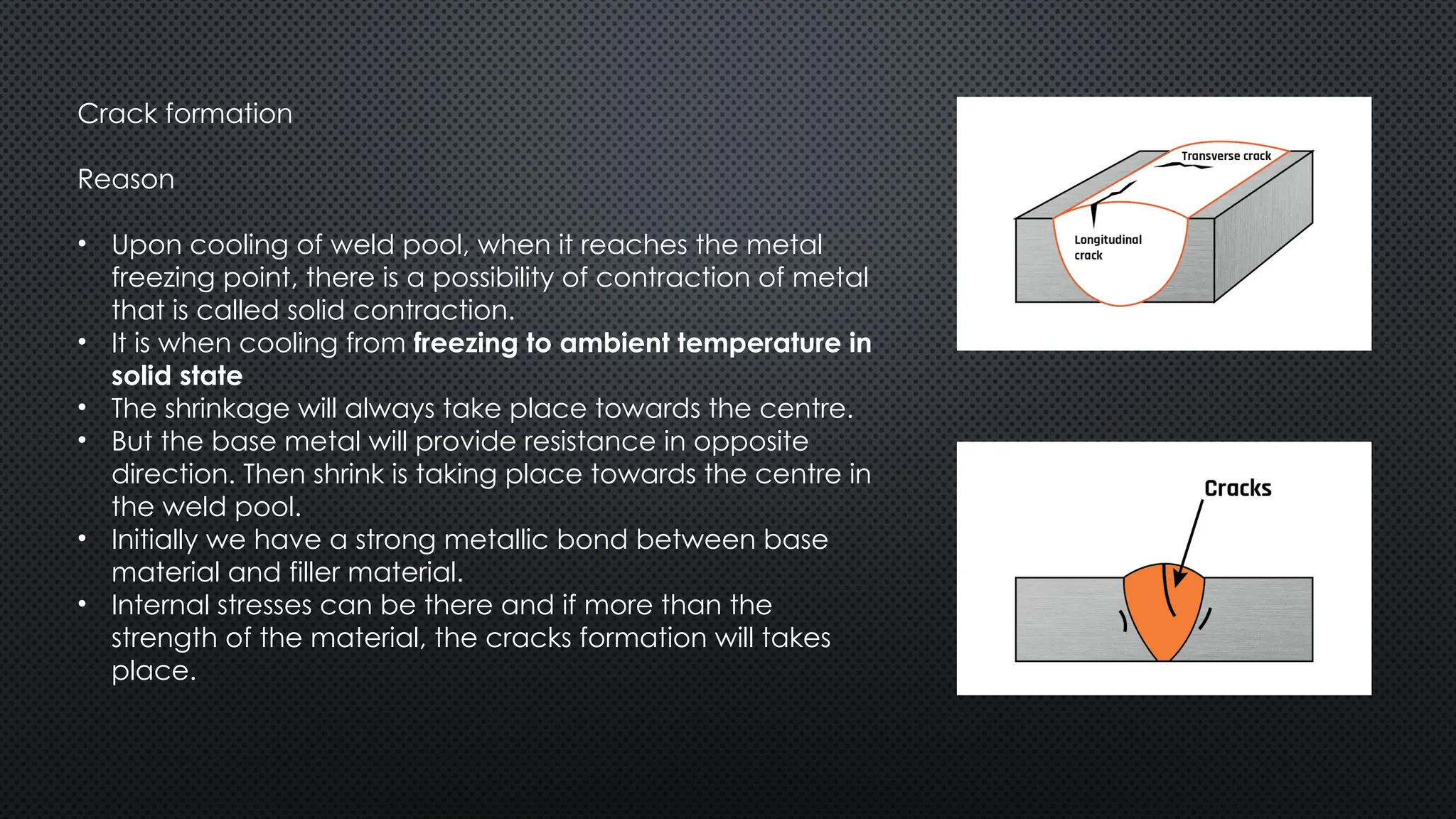
Crack formation
Reason
• Uponcooling of weld pool, when it reaches the metal
freezing point, there is a possibility of contraction of metal
that is called solid contraction.
• It is when cooling from freezing to ambient temperature in
solid state
• The shrinkage will always take place towards the centre.
• But the base metal will provide resistance in opposite
direction. Then shrink is taking place towards the centre in
the weld pool.
• Initially we have a strong metallic bond between base
material and filler material.
• Internal stresses can be there and if more than the
strength of the material, the cracks formation will takes
place.
71.
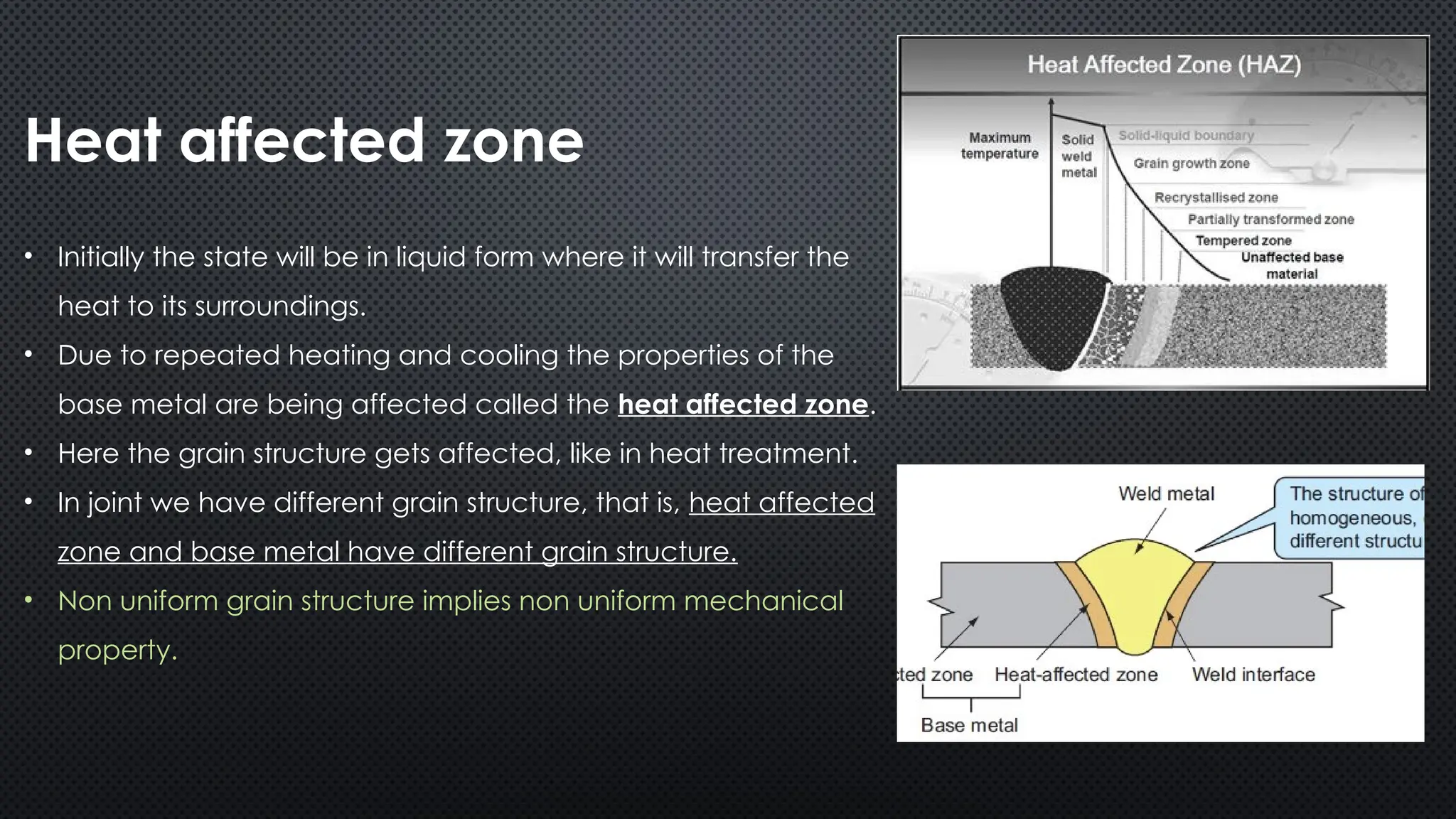
Heat affected zone
•Initially the state will be in liquid form where it will transfer the
heat to its surroundings.
• Due to repeated heating and cooling the properties of the
base metal are being affected called the heat affected zone.
• Here the grain structure gets affected, like in heat treatment.
• In joint we have different grain structure, that is, heat affected
zone and base metal have different grain structure.
• Non uniform grain structure implies non uniform mechanical
property.
72.
Remedies
• To getuniform mechanical properties in this area and to minimise the crack
formation we have to go for heat treatment.
• Like annealing - Due to this internal stresses can be relieved.
• As uniform heat transfer will lead to uniform joint formation thus, uniform
mechanical properties.
73.
Composition of fillermaterial
• If joining two similar materials
Composition same as of base material
• If joining two different materials
Filler material is soluble in two different base material
74.
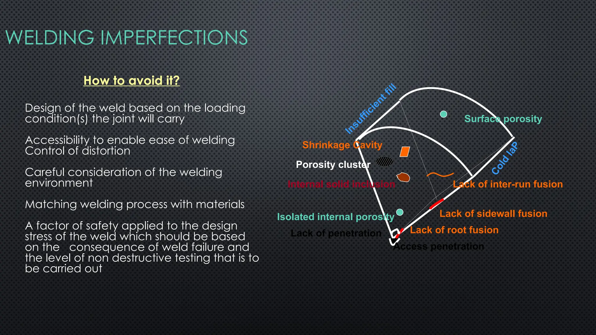
WELDING IMPERFECTIONS
Porosity cluster
ShrinkageCavity
Isolated internal porosity
Surface porosity
Internal solid inclusion Lack of inter-run fusion
Lack of sidewall fusion
Lack of root fusion
Lack of penetration
Access penetration
Insufficient fill
C
o
l
d
l
a
P
How to avoid it?
Design of the weld based on the loading
condition(s) the joint will carry
Accessibility to enable ease of welding
Control of distortion
Careful consideration of the welding
environment
Matching welding process with materials
A factor of safety applied to the design
stress of the weld which should be based
on the consequence of weld failure and
the level of non destructive testing that is to
be carried out
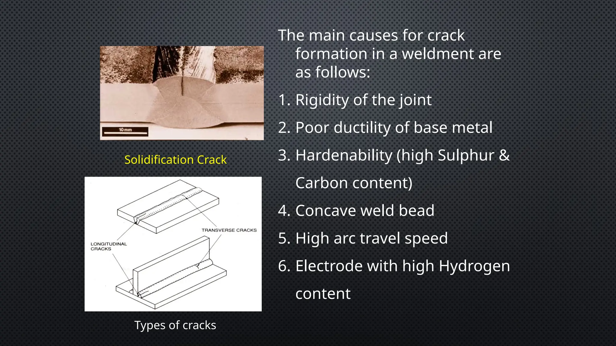
Solidification Crack
The maincauses for crack
formation in a weldment are
as follows:
1. Rigidity of the joint
2. Poor ductility of base metal
3. Hardenability (high Sulphur &
Carbon content)
4. Concave weld bead
5. High arc travel speed
6. Electrode with high Hydrogen
content
Types of cracks
77.
Some remedies toreduce appearance of cracks are as follows :-
(a) Apply preheat to the base metal.
(b) Relieve residual stresses mechanically.
(c) Minimize shrinkage stresses using back step or block welding sequence.
(d) Change weld current and travel speed (to effect slower cooling rate).
(e) Bake electrodes to remove moisture.
(f) Reduce root opening; build-up edge with weld metal.
(g) Increase electrode size for small weld bead, raise welding current, and reduce
travel speed.
(h) For high sulphur base metal, use filler metal low in sulphur.
(j) Use of jigs and fixtures.
(k) Reduce welding time.
(l) Weld outward from the centre point.
(m)Removal of shrinkage forces during or after welding.
(n) Breaking down of forge weld mends into sub assemblies.
78.
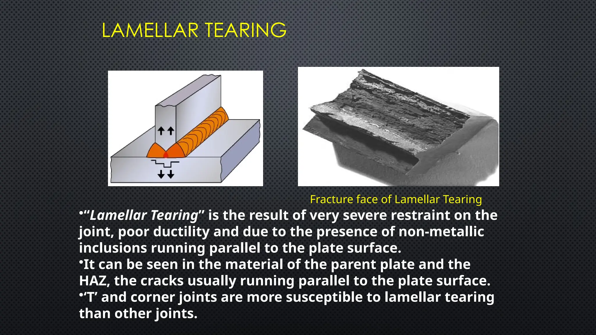
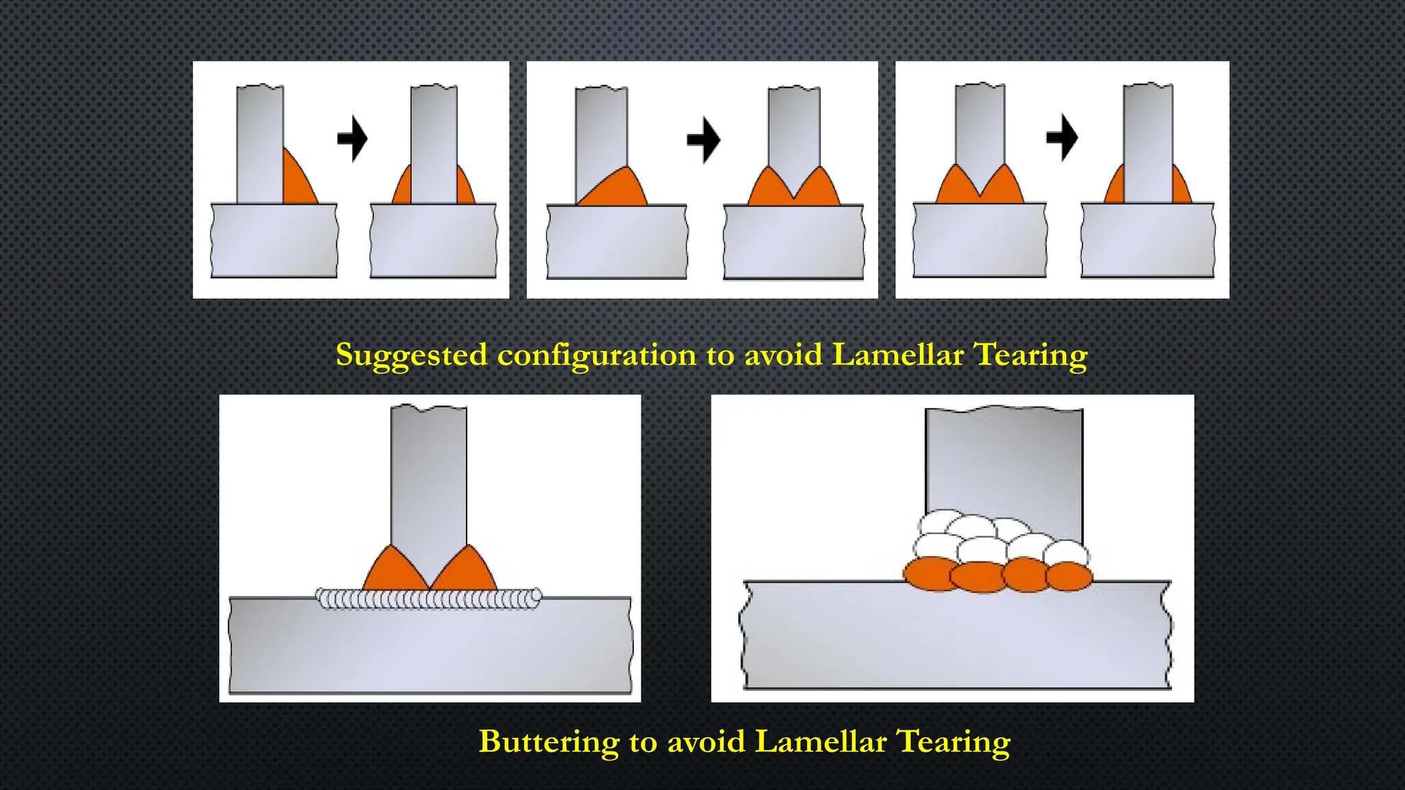
LAMELLAR TEARING
Fracture faceof Lamellar Tearing
•“Lamellar Tearing” is the result of very severe restraint on the
joint, poor ductility and due to the presence of non-metallic
inclusions running parallel to the plate surface.
•It can be seen in the material of the parent plate and the
HAZ, the cracks usually running parallel to the plate surface.
•‘T’ and corner joints are more susceptible to lamellar tearing
than other joints.
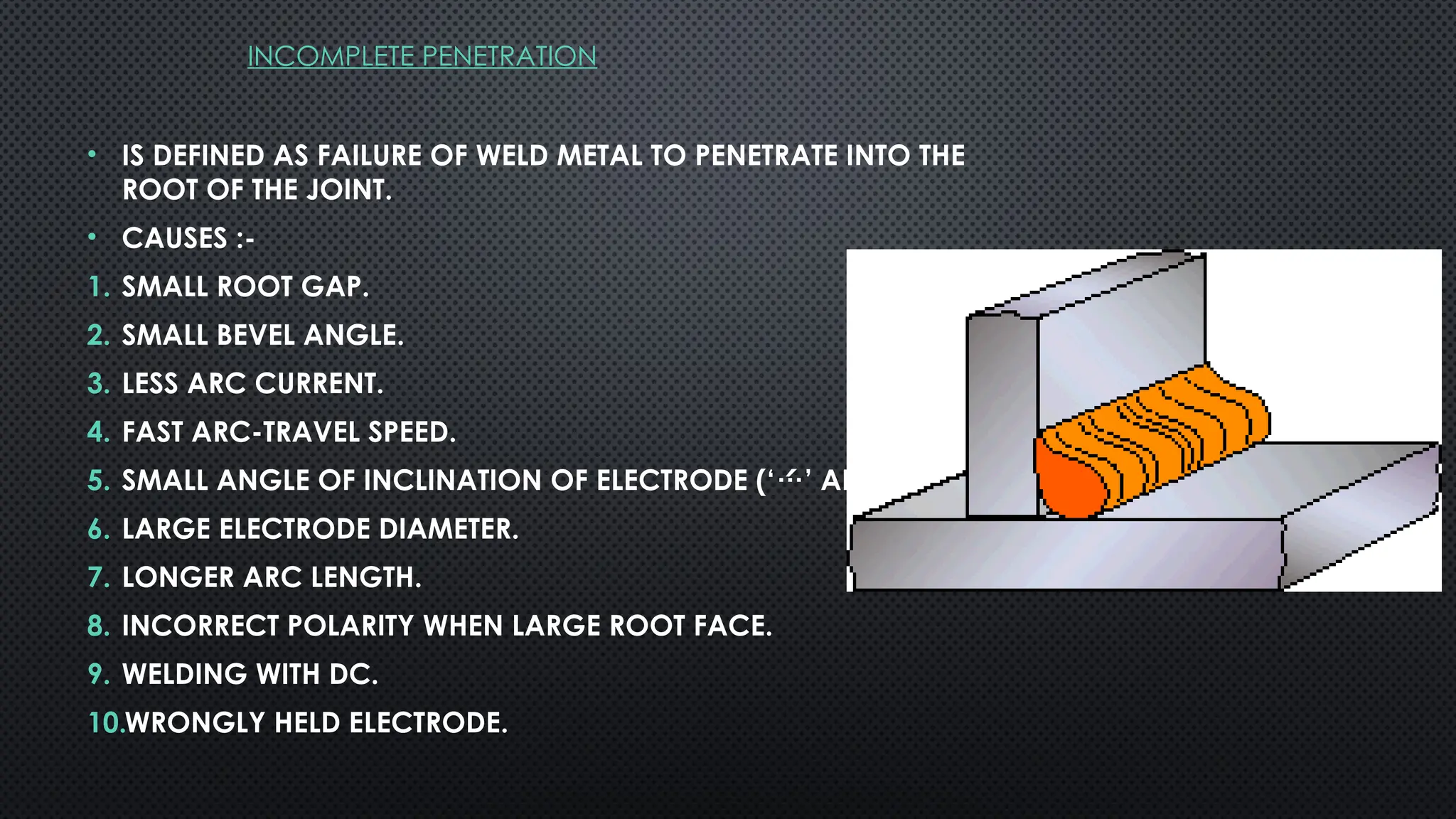
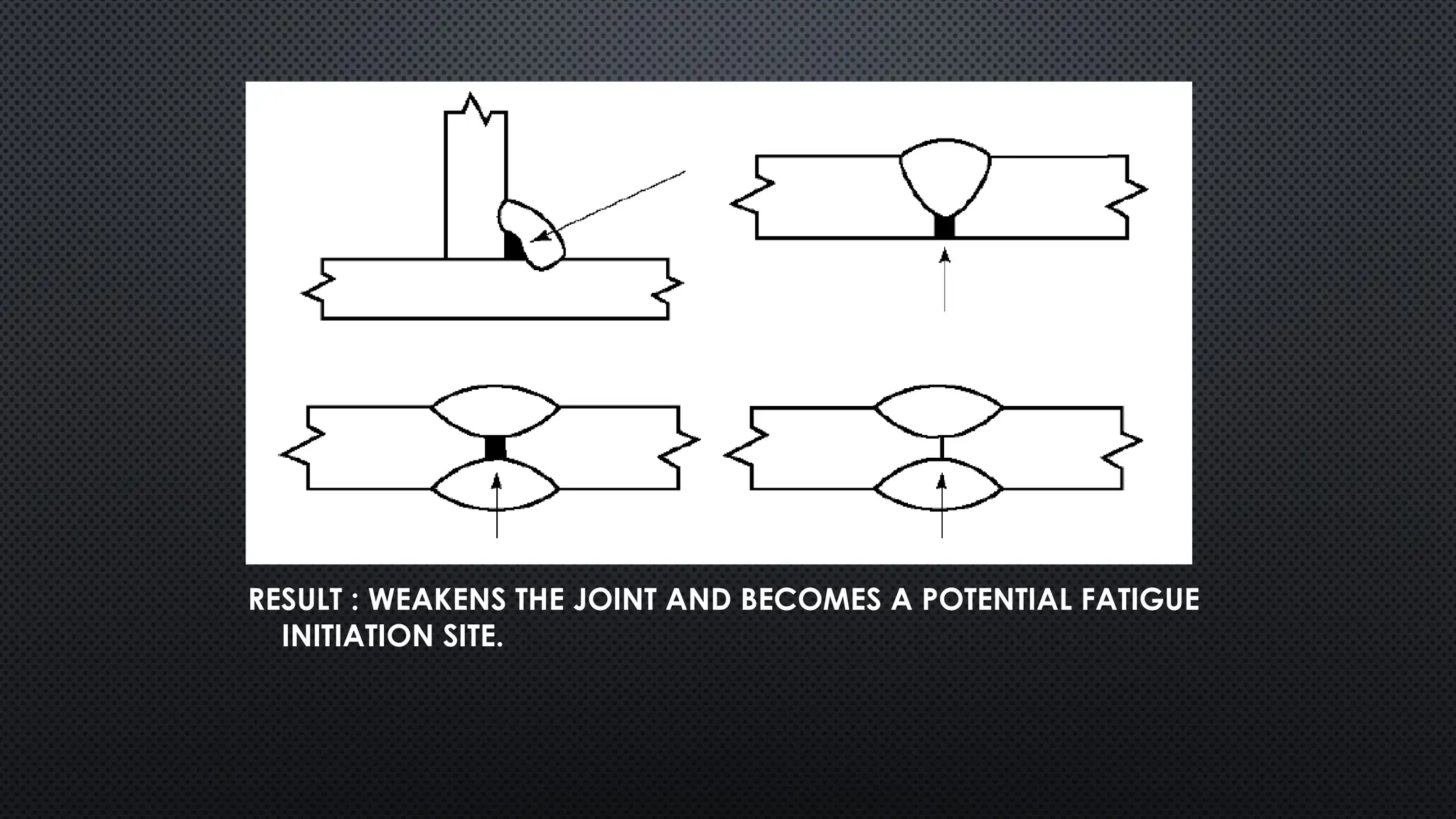
INCOMPLETE PENETRATION
• ISDEFINED AS FAILURE OF WELD METAL TO PENETRATE INTO THE
ROOT OF THE JOINT.
• CAUSES :-
1. SMALL ROOT GAP.
2. SMALL BEVEL ANGLE.
3. LESS ARC CURRENT.
4. FAST ARC-TRAVEL SPEED.
5. SMALL ANGLE OF INCLINATION OF ELECTRODE (‘’ ANGLE).
6. LARGE ELECTRODE DIAMETER.
7. LONGER ARC LENGTH.
8. INCORRECT POLARITY WHEN LARGE ROOT FACE.
9. WELDING WITH DC.
10.WRONGLY HELD ELECTRODE.
81.
RESULT : WEAKENSTHE JOINT AND BECOMES A POTENTIAL FATIGUE
INITIATION SITE.
82.
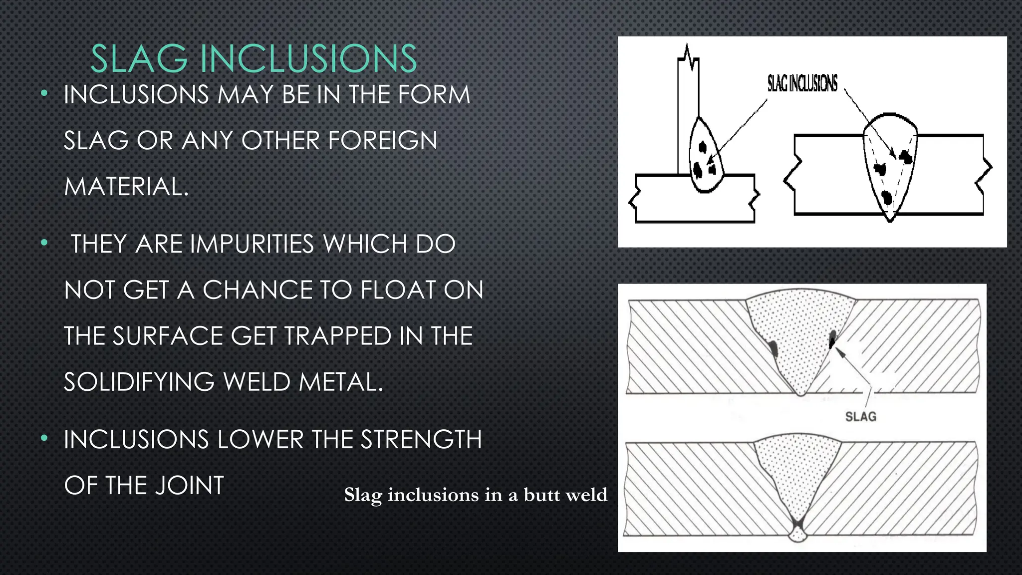
SLAG INCLUSIONS
• INCLUSIONSMAY BE IN THE FORM
SLAG OR ANY OTHER FOREIGN
MATERIAL.
• THEY ARE IMPURITIES WHICH DO
NOT GET A CHANCE TO FLOAT ON
THE SURFACE GET TRAPPED IN THE
SOLIDIFYING WELD METAL.
• INCLUSIONS LOWER THE STRENGTH
OF THE JOINT Slag inclusions in a butt weld
83.
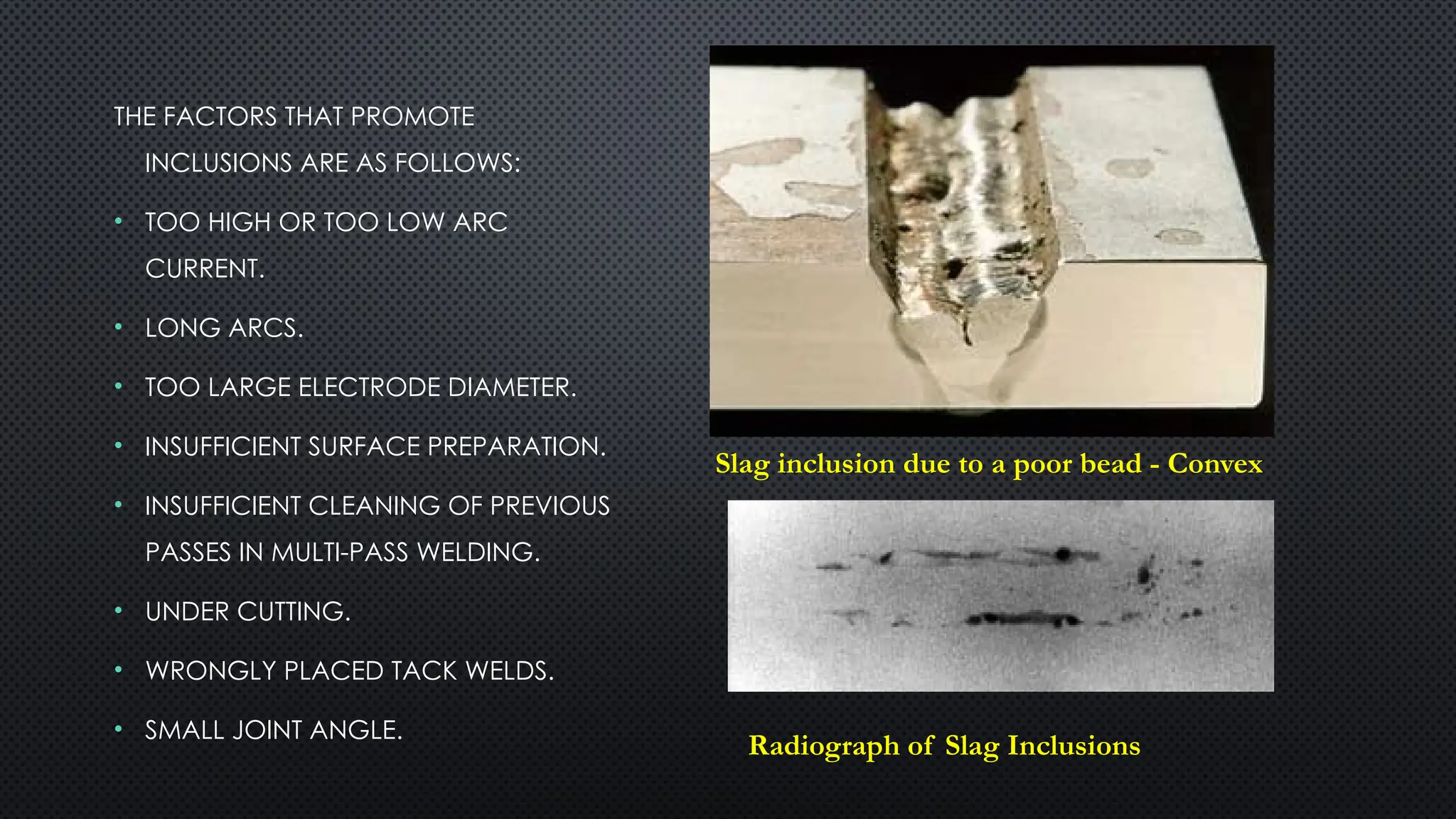
THE FACTORS THATPROMOTE
INCLUSIONS ARE AS FOLLOWS:
• TOO HIGH OR TOO LOW ARC
CURRENT.
• LONG ARCS.
• TOO LARGE ELECTRODE DIAMETER.
• INSUFFICIENT SURFACE PREPARATION.
• INSUFFICIENT CLEANING OF PREVIOUS
PASSES IN MULTI-PASS WELDING.
• UNDER CUTTING.
• WRONGLY PLACED TACK WELDS.
• SMALL JOINT ANGLE.
Slag inclusion due to a poor bead - Convex
Radiograph of Slag Inclusions
84.
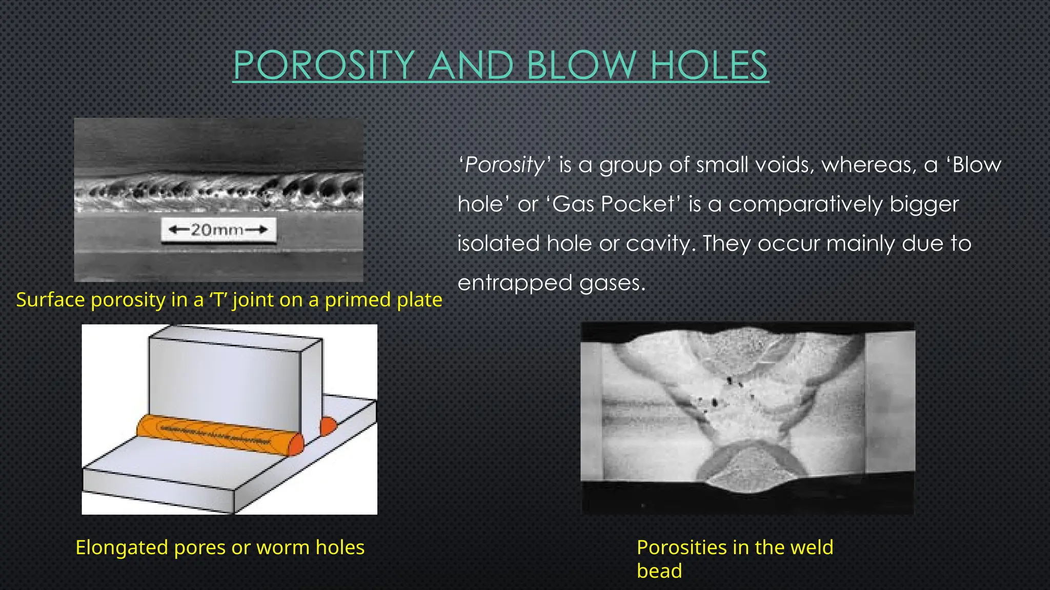
POROSITY AND BLOWHOLES
Surface porosity in a ‘T’ joint on a primed plate
‘Porosity’ is a group of small voids, whereas, a ‘Blow
hole’ or ‘Gas Pocket’ is a comparatively bigger
isolated hole or cavity. They occur mainly due to
entrapped gases.
Porosities in the weld
bead
Elongated pores or worm holes
85.
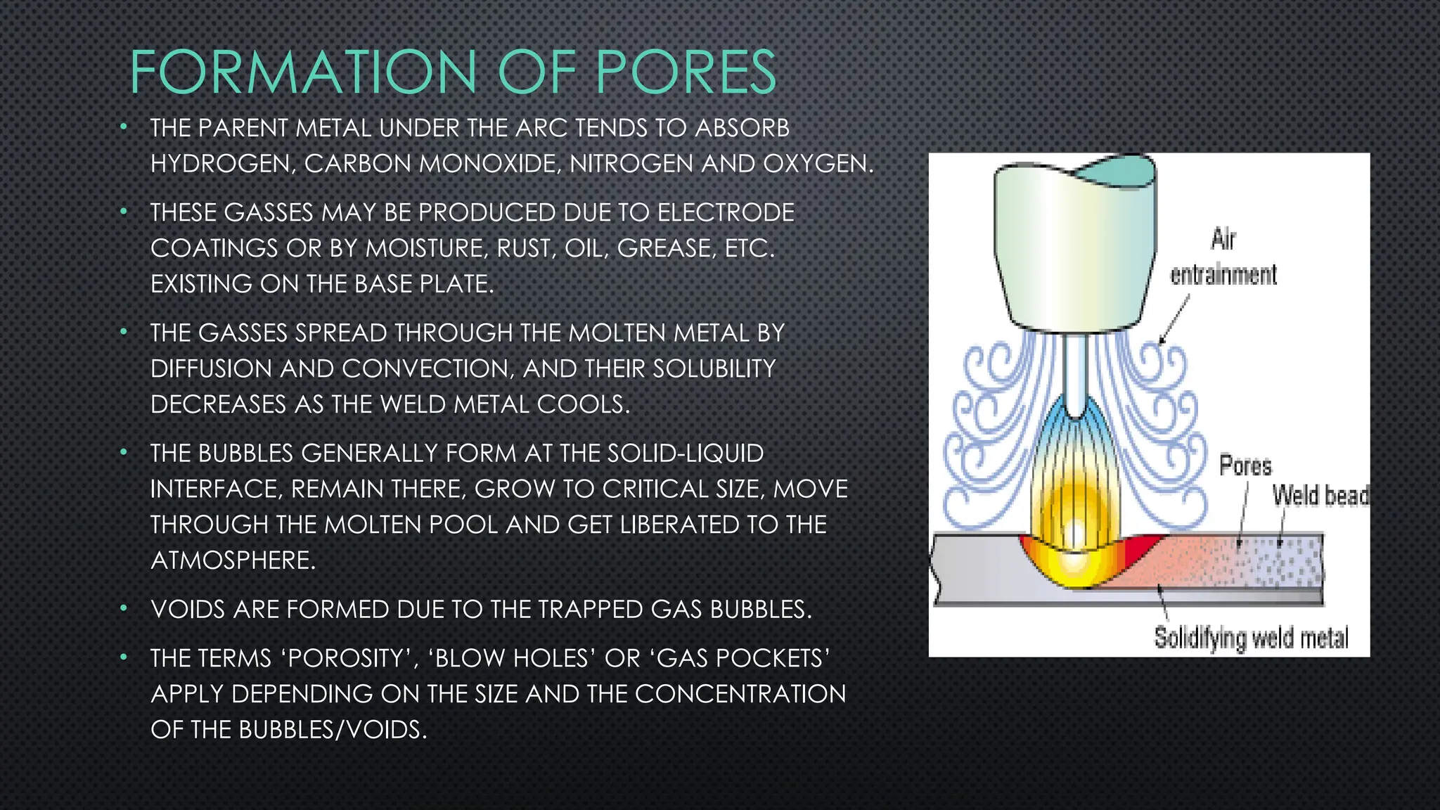
FORMATION OF PORES
•THE PARENT METAL UNDER THE ARC TENDS TO ABSORB
HYDROGEN, CARBON MONOXIDE, NITROGEN AND OXYGEN.
• THESE GASSES MAY BE PRODUCED DUE TO ELECTRODE
COATINGS OR BY MOISTURE, RUST, OIL, GREASE, ETC.
EXISTING ON THE BASE PLATE.
• THE GASSES SPREAD THROUGH THE MOLTEN METAL BY
DIFFUSION AND CONVECTION, AND THEIR SOLUBILITY
DECREASES AS THE WELD METAL COOLS.
• THE BUBBLES GENERALLY FORM AT THE SOLID-LIQUID
INTERFACE, REMAIN THERE, GROW TO CRITICAL SIZE, MOVE
THROUGH THE MOLTEN POOL AND GET LIBERATED TO THE
ATMOSPHERE.
• VOIDS ARE FORMED DUE TO THE TRAPPED GAS BUBBLES.
• THE TERMS ‘POROSITY’, ‘BLOW HOLES’ OR ‘GAS POCKETS’
APPLY DEPENDING ON THE SIZE AND THE CONCENTRATION
OF THE BUBBLES/VOIDS.
86.
FACTORS LEADING TOTHESE DEFECTS ARE
AS FOLLOWS:
• IMPROPER ELECTRODE (OR COATING) OR DAMAGED/DAMP
COATING.
• LONGER ARCS.
• FASTER ARC TRAVEL SPEEDS.
• TOO HIGH/LOW CURRENTS.
• INCORRECT WELDING TECHNIQUES.
• IMPURITIES PRESENT ON THE JOB SURFACE.
• IMPROPER BASE-METAL CONFIGURATION (HIGH ‘S’ OR ‘C’
CONTENT).
87.
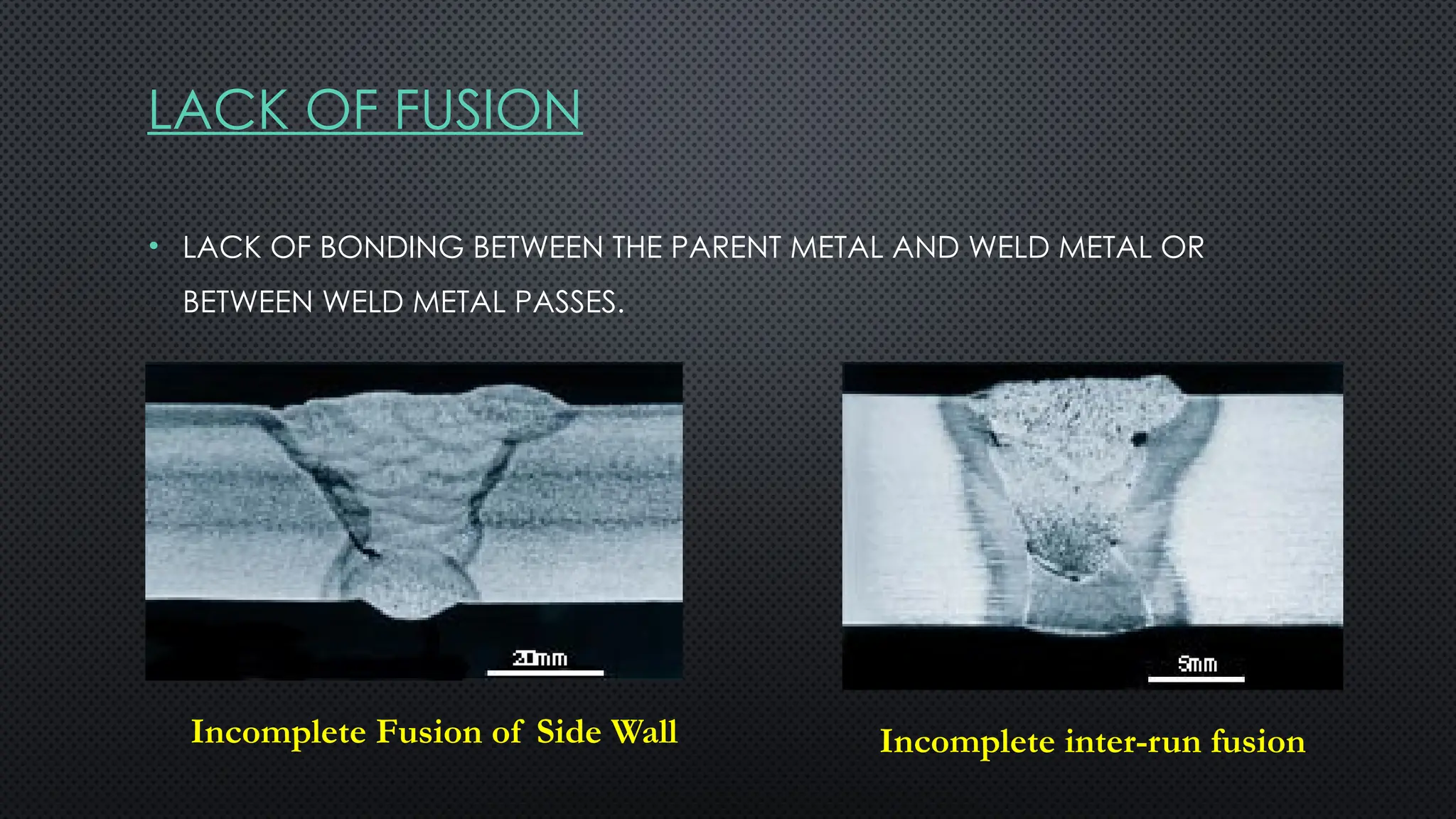
LACK OF FUSION
•LACK OF BONDING BETWEEN THE PARENT METAL AND WELD METAL OR
BETWEEN WELD METAL PASSES.
Incomplete Fusion of Side Wall Incomplete inter-run fusion
88.
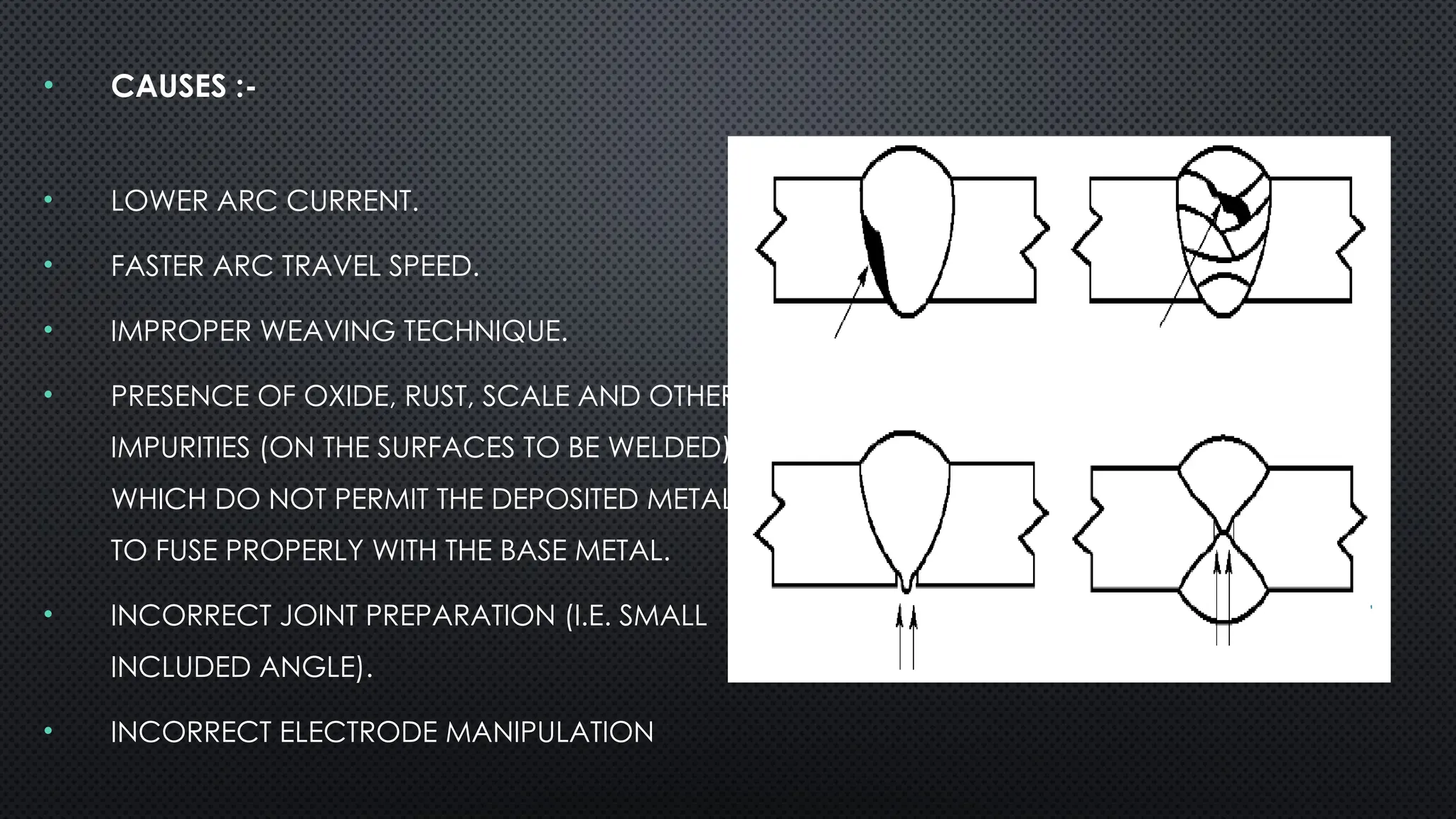
• CAUSES :-
•LOWER ARC CURRENT.
• FASTER ARC TRAVEL SPEED.
• IMPROPER WEAVING TECHNIQUE.
• PRESENCE OF OXIDE, RUST, SCALE AND OTHER
IMPURITIES (ON THE SURFACES TO BE WELDED),
WHICH DO NOT PERMIT THE DEPOSITED METAL
TO FUSE PROPERLY WITH THE BASE METAL.
• INCORRECT JOINT PREPARATION (I.E. SMALL
INCLUDED ANGLE).
• INCORRECT ELECTRODE MANIPULATION
89.
MEASURES TO AVOID/REDUCEPOOR FUSION
ARE:
• (A) FOLLOW CORRECT WELDING PROCEDURES.
• (B) MAINTAIN PROPER ELECTRODE POSITION.
• (C) REPOSITION WORK, LOWER CURRENT OR INCREASE ARC
TRAVEL SPEED.
• (D) CLEAN WELD SURFACE PRIOR TO WELDING.
90.
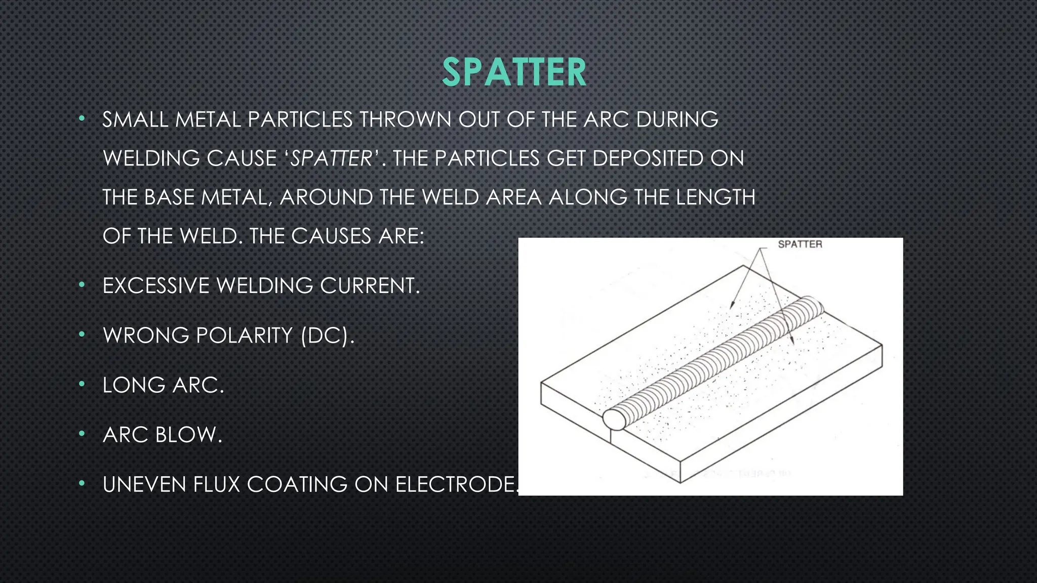
SPATTER
• SMALL METALPARTICLES THROWN OUT OF THE ARC DURING
WELDING CAUSE ‘SPATTER’. THE PARTICLES GET DEPOSITED ON
THE BASE METAL, AROUND THE WELD AREA ALONG THE LENGTH
OF THE WELD. THE CAUSES ARE:
• EXCESSIVE WELDING CURRENT.
• WRONG POLARITY (DC).
• LONG ARC.
• ARC BLOW.
• UNEVEN FLUX COATING ON ELECTRODE.
91.
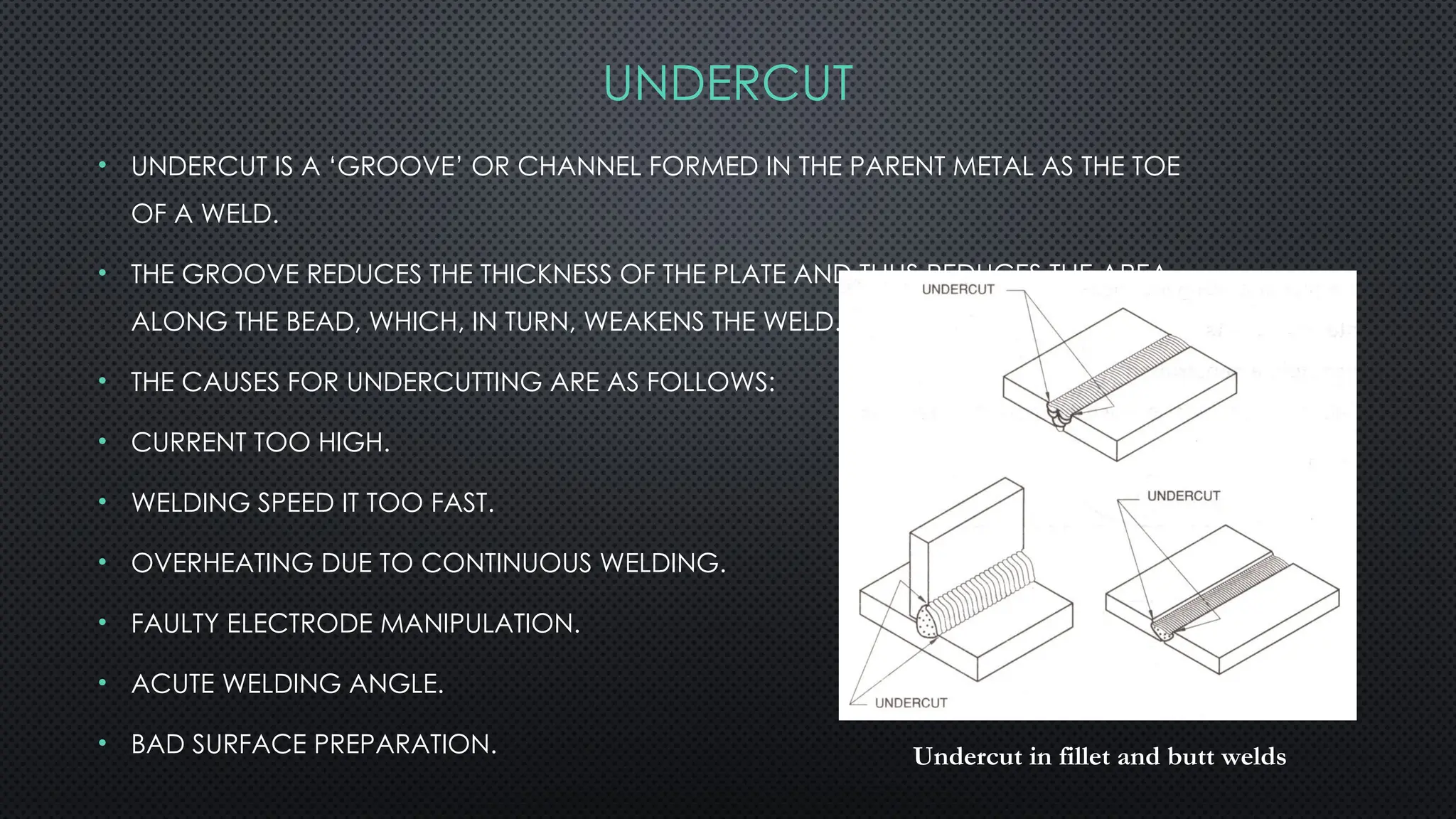
• UNDERCUT ISA ‘GROOVE’ OR CHANNEL FORMED IN THE PARENT METAL AS THE TOE
OF A WELD.
• THE GROOVE REDUCES THE THICKNESS OF THE PLATE AND THUS REDUCES THE AREA
ALONG THE BEAD, WHICH, IN TURN, WEAKENS THE WELD.
• THE CAUSES FOR UNDERCUTTING ARE AS FOLLOWS:
• CURRENT TOO HIGH.
• WELDING SPEED IT TOO FAST.
• OVERHEATING DUE TO CONTINUOUS WELDING.
• FAULTY ELECTRODE MANIPULATION.
• ACUTE WELDING ANGLE.
• BAD SURFACE PREPARATION. Undercut in fillet and butt welds
UNDERCUT
92.
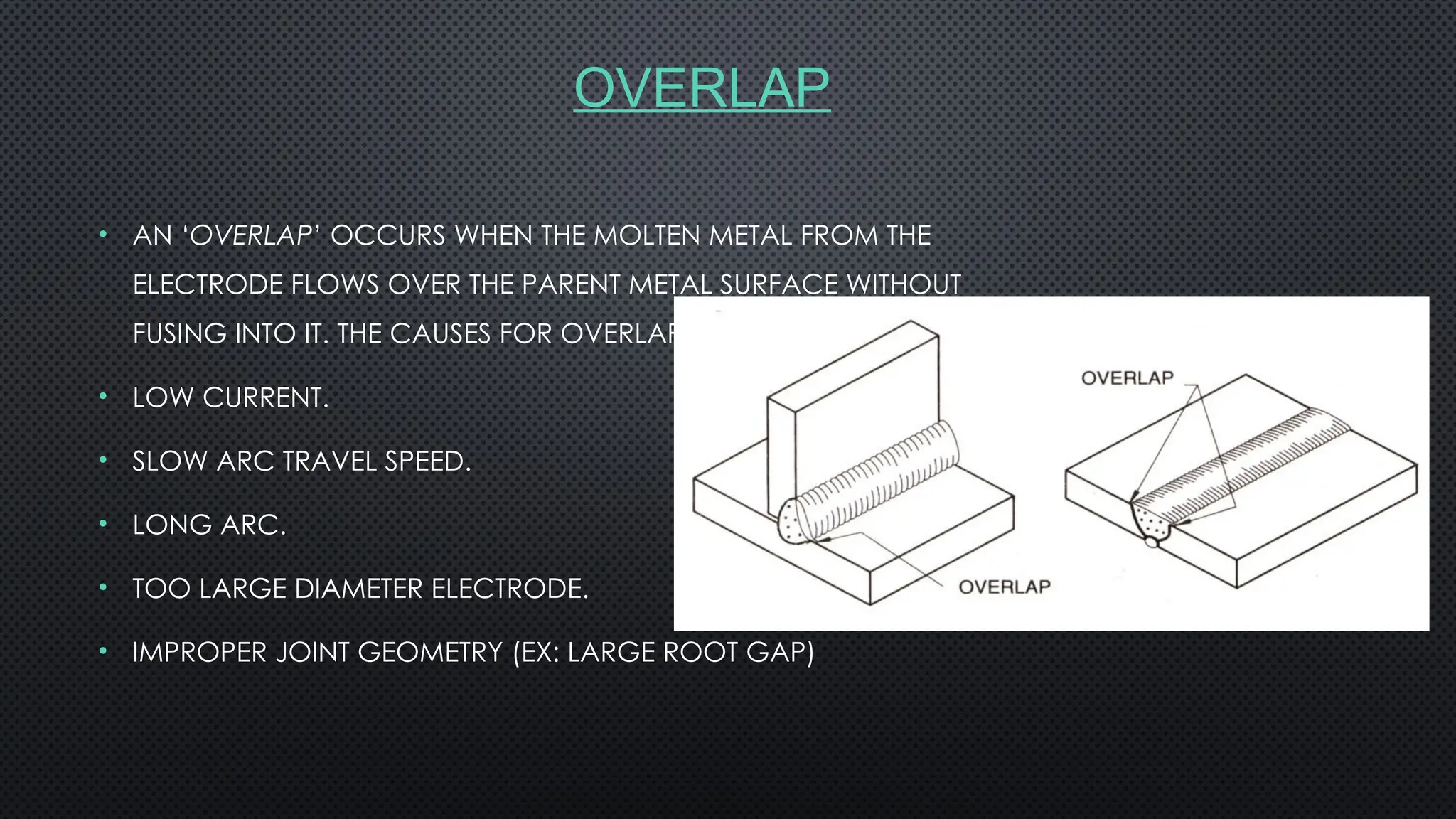
OVERLAP
• AN ‘OVERLAP’OCCURS WHEN THE MOLTEN METAL FROM THE
ELECTRODE FLOWS OVER THE PARENT METAL SURFACE WITHOUT
FUSING INTO IT. THE CAUSES FOR OVERLAP ARE AS FOLLOWS:
• LOW CURRENT.
• SLOW ARC TRAVEL SPEED.
• LONG ARC.
• TOO LARGE DIAMETER ELECTRODE.
• IMPROPER JOINT GEOMETRY (EX: LARGE ROOT GAP)
93.
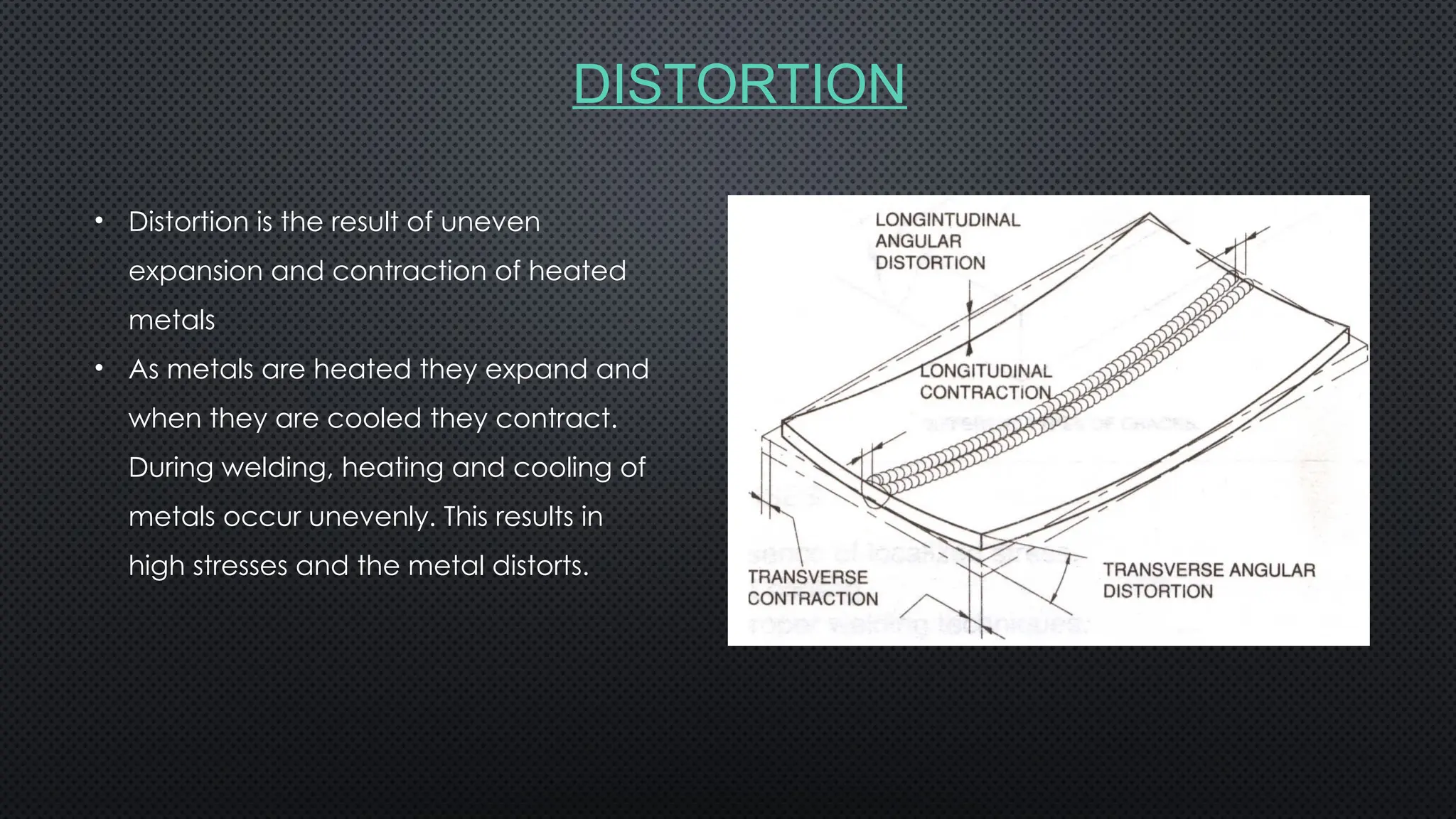
DISTORTION
• Distortion isthe result of uneven
expansion and contraction of heated
metals
• As metals are heated they expand and
when they are cooled they contract.
During welding, heating and cooling of
metals occur unevenly. This results in
high stresses and the metal distorts.
DISTORTION CONTROL
• PRECAUTIONSCAN BE TAKEN TO AVOID OR REDUCE WELD
DISTORTIONS BEFORE, DURING OR AFTER WELDING.
• THE CONTROL OF DISTORTION BEFORE WELDING CAN BE
FACILITATED BY:-
• TACK WELDING.
• USING JIGS, CLAMPS AND FIXTURES.
• ENSURING UNIFORM PRE-HEATING.
• PRE-SETTING.
97.
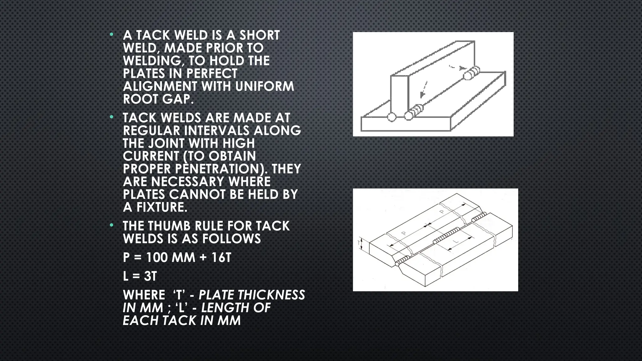
• A TACKWELD IS A SHORT
WELD, MADE PRIOR TO
WELDING, TO HOLD THE
PLATES IN PERFECT
ALIGNMENT WITH UNIFORM
ROOT GAP.
• TACK WELDS ARE MADE AT
REGULAR INTERVALS ALONG
THE JOINT WITH HIGH
CURRENT (TO OBTAIN
PROPER PENETRATION). THEY
ARE NECESSARY WHERE
PLATES CANNOT BE HELD BY
A FIXTURE.
• THE THUMB RULE FOR TACK
WELDS IS AS FOLLOWS
P = 100 MM + 16T
L = 3T
WHERE ‘T’ - PLATE THICKNESS
IN MM ; ‘L’ - LENGTH OF
EACH TACK IN MM
98.
JIGS AND FIXTURES
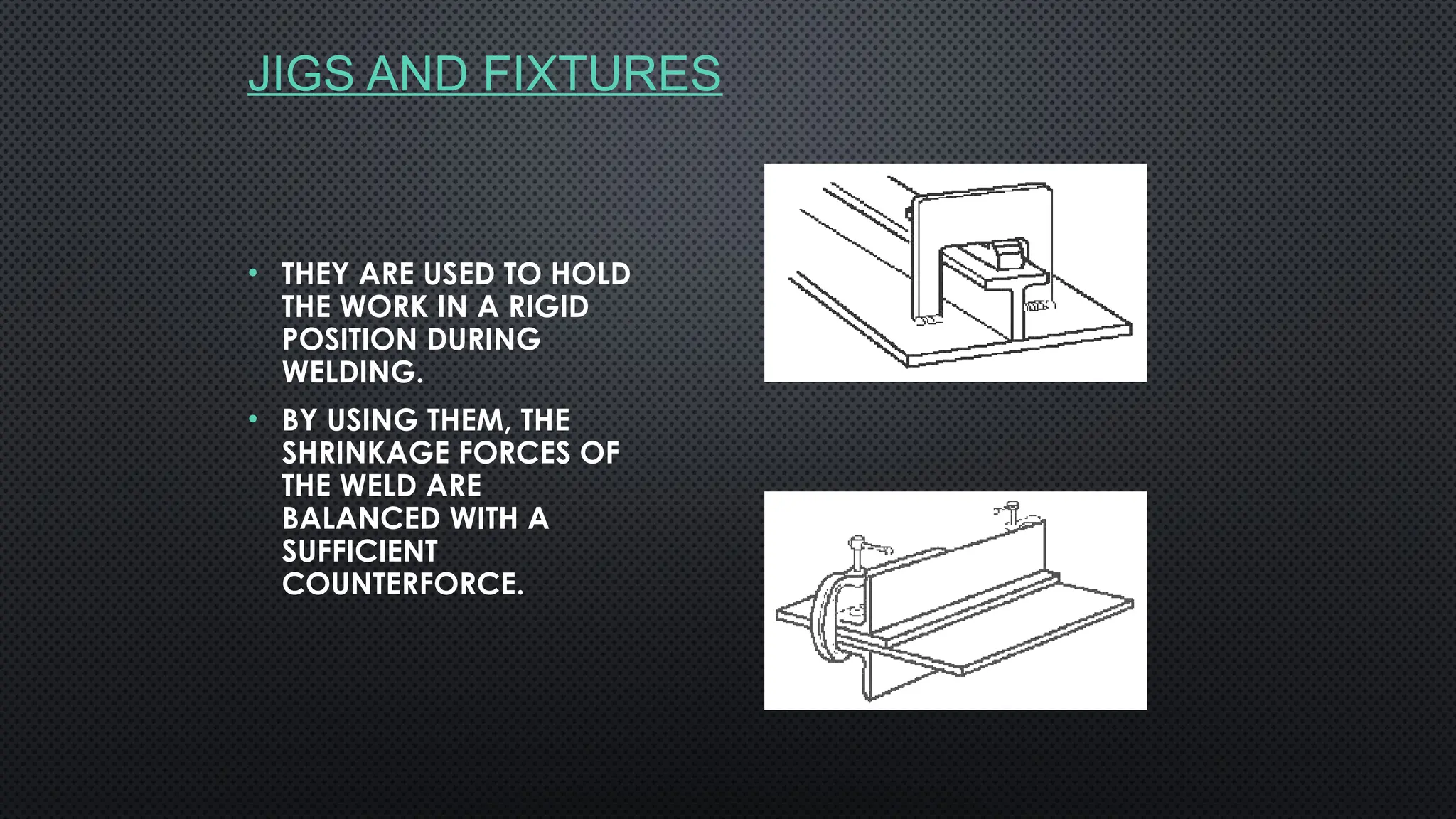
•THEY ARE USED TO HOLD
THE WORK IN A RIGID
POSITION DURING
WELDING.
• BY USING THEM, THE
SHRINKAGE FORCES OF
THE WELD ARE
BALANCED WITH A
SUFFICIENT
COUNTERFORCE.
99.
PRE - HEATING
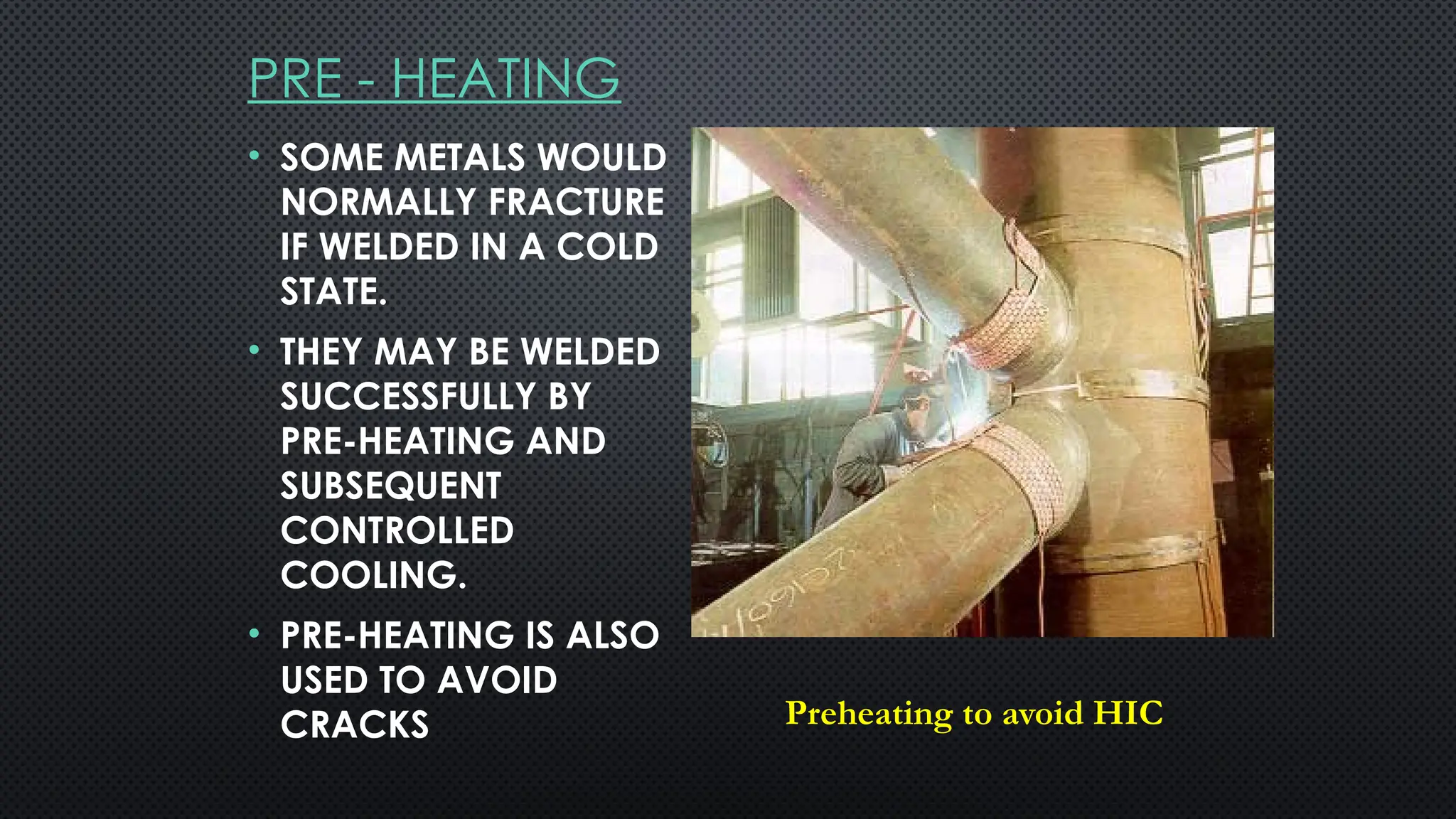
•SOME METALS WOULD
NORMALLY FRACTURE
IF WELDED IN A COLD
STATE.
• THEY MAY BE WELDED
SUCCESSFULLY BY
PRE-HEATING AND
SUBSEQUENT
CONTROLLED
COOLING.
• PRE-HEATING IS ALSO
USED TO AVOID
CRACKS Preheating to avoid HIC
100.
PRE-SETTING
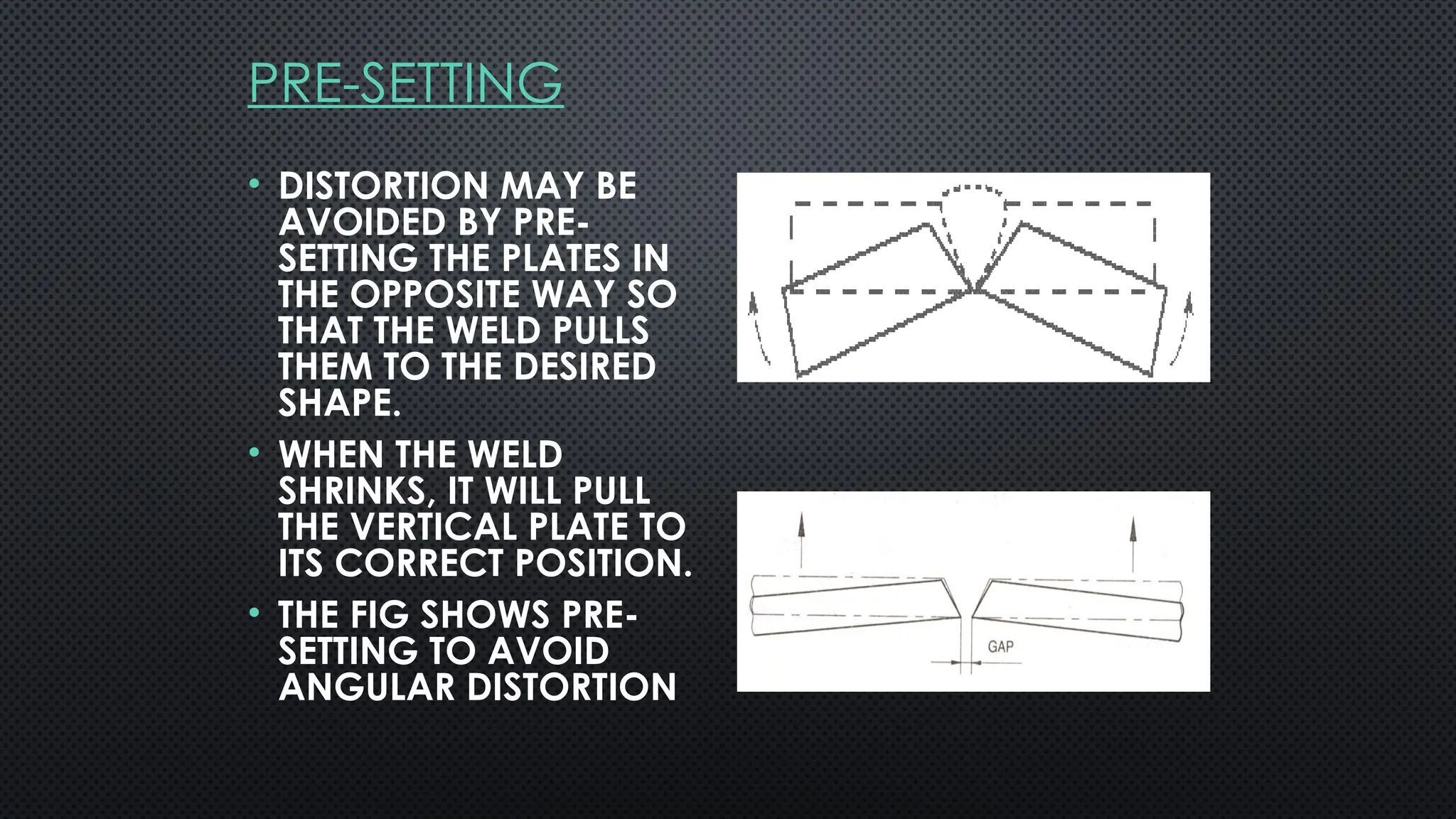
• DISTORTION MAYBE
AVOIDED BY PRE-
SETTING THE PLATES IN
THE OPPOSITE WAY SO
THAT THE WELD PULLS
THEM TO THE DESIRED
SHAPE.
• WHEN THE WELD
SHRINKS, IT WILL PULL
THE VERTICAL PLATE TO
ITS CORRECT POSITION.
• THE FIG SHOWS PRE-
SETTING TO AVOID
ANGULAR DISTORTION
101.
DURING WELDING
• BACK-STEPWELDING.
• INTERMITTENT “CHAIN” & “STAGGERED”
WELDING.
• PLANNED WANDERING METHOD.
• A CORRECT WELDING PROCEDURE TO
REDUCE THE SIZE OF THE WELD BEADS.
• EXCESSIVE WELDING SHOULD BE AVOIDED.
102.
BACK STEP WELDING
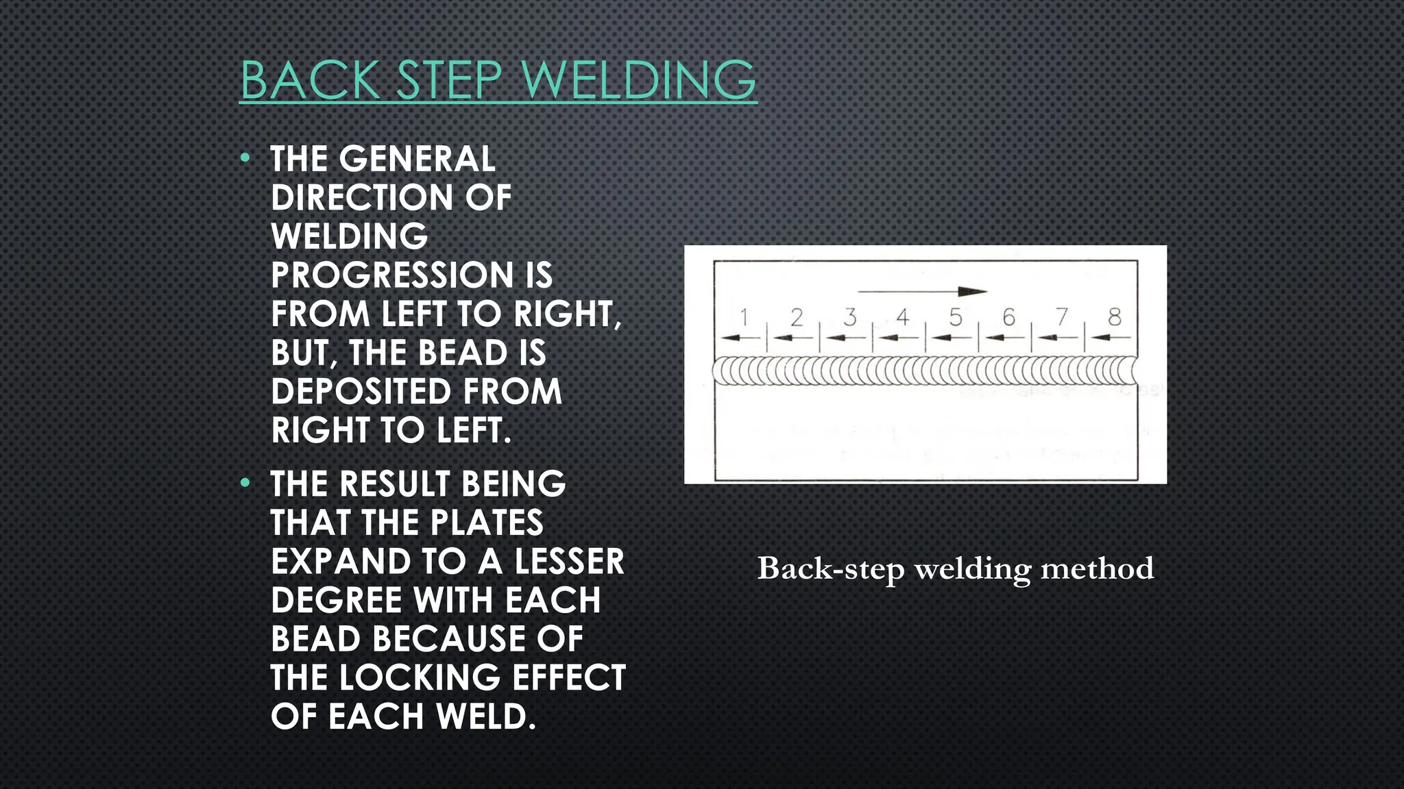
•THE GENERAL
DIRECTION OF
WELDING
PROGRESSION IS
FROM LEFT TO RIGHT,
BUT, THE BEAD IS
DEPOSITED FROM
RIGHT TO LEFT.
• THE RESULT BEING
THAT THE PLATES
EXPAND TO A LESSER
DEGREE WITH EACH
BEAD BECAUSE OF
THE LOCKING EFFECT
OF EACH WELD.
Back-step welding method
103.
INTERMITTENT WELDING
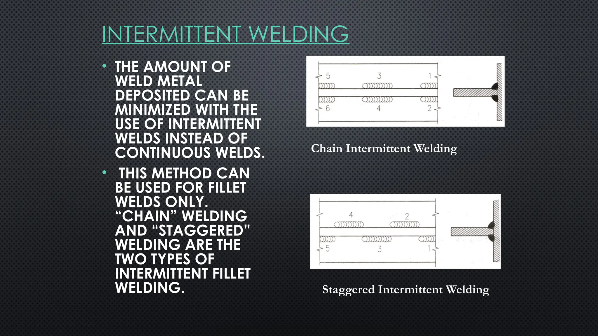
• THEAMOUNT OF
WELD METAL
DEPOSITED CAN BE
MINIMIZED WITH THE
USE OF INTERMITTENT
WELDS INSTEAD OF
CONTINUOUS WELDS.
• THIS METHOD CAN
BE USED FOR FILLET
WELDS ONLY.
“CHAIN” WELDING
AND “STAGGERED”
WELDING ARE THE
TWO TYPES OF
INTERMITTENT FILLET
WELDING.
Chain Intermittent Welding
Staggered Intermittent Welding
104.
PLANNED WANDERING METHOD
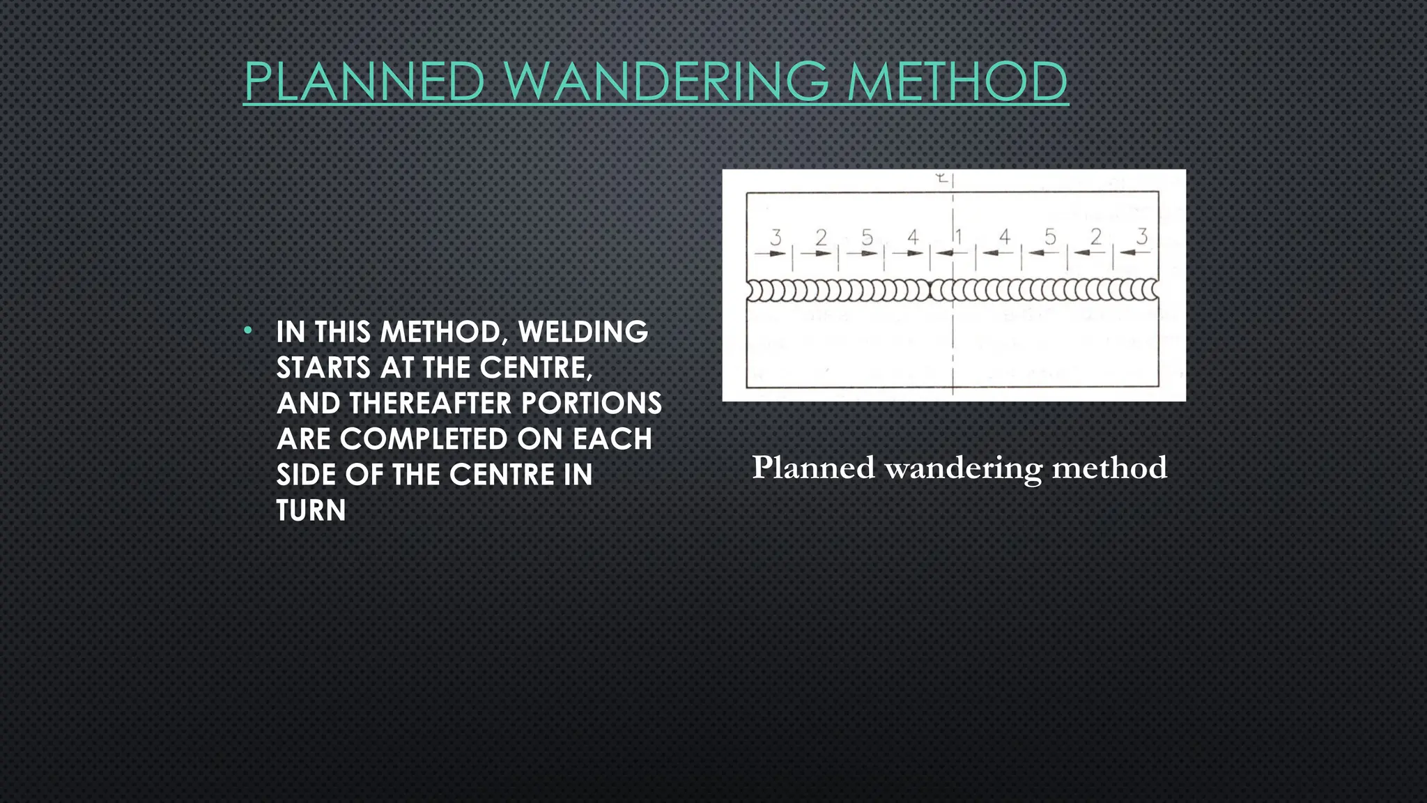
•IN THIS METHOD, WELDING
STARTS AT THE CENTRE,
AND THEREAFTER PORTIONS
ARE COMPLETED ON EACH
SIDE OF THE CENTRE IN
TURN
Planned wandering method
105.
AFTER WELDING
THE CONTROLOF DISTORTION AFTER WELDING CAN BE
FACILITATED BY THE FOLLOWING:-
• SLOW COOLING.
• FLAME STRAIGHTENING OR CONTRA HEATING.
• ANNEALING.
• STRESS RELIEVING.
• NORMALISING.
• MECHANICAL STRAIGHTENING
106.
TIPS TO AVOIDDISTORTION
• IT IS POSSIBLE TO REDUCE THE EFFECT OF
SHRINKAGE-FORCE BY CORRECT EDGE
PREPARATION. THIS WILL ENSURE PROPER
FUSION AT THE ROOT OF THE WELD WITH A
MINIMUM OF WELD METAL.
• THE CORRECT WELDING PROCEDURE USED A
GREATER NUMBER OF WELDED RUNS
POSITIONED TO REFINE THE GRAIN SIZE OF THE
WELD METAL IN THE PREVIOUS LAYER.
• A SMALL NUMBER IF HEAVY RUNS WILL CAUSE
MORE DISTORTION DUE TO THE GREATER HEAT
INPUT, AND THE CONTRACTION STRESSES SET
UP BY THE COOLING OF THE LARGER DEPOSIT
107.
TESTING THE WELDS
HardnessTest: The ability of a material to resist indentation. Diamond or steel ball to be used to form an
indentation.
Toughness Test: The ability of a material to absorb impact energy. Test types are Charpy V, Izod, and
Crack tip opening displacement.
Ductility ( Elongation %): The ability to deform under tensile force. Tensile Strength: The ability to resist a
pulling force. The test shows the yield point and tensile strength.
Non-destructive testing is used to check beyond visual inspection limitation
Penetrate Testing: check surface cracks, and leaks in weldment. There are two types of colour contrast
and fluorescent penetration. It consist of penetrant, and developer.
Magnetic Particle Testing: Check surface defects, especially surface cracks.It can show also subsurface
imperfections. It consist of contrast, magnet - ink and magnetic field.
Ultrasonic Testing: Check surface and subsurface flaws including those too small to be detected by other
tests. It consist of added couplant and CRT display unit and probe.
Radiographic Testing: Check internal flaws like cracks, porosity, blowholes, incomplete root penetration,
inclusions, and burn through. Radiographic rays are two X rays ( from cathode ray tube C.R.T) and
Gamma rays( from a radioactive isotope). It consist of a prepared file, exposure to a radioactive source
the developed X ray film.
Radiographic test does not detect the crack in plane in same direction of the ray beam ( Ultrasonic test
can detect that) it detect the defects in right angle to beam spread.
108.
INSPECTION & NON-DESTRUCTIVETESTING OF WELDS
• WELDED JOINTS IN A STRUCTURE ARE EXPECTED TO POSSESS CERTAIN SERVICE-
RELATED CAPABILITIES.
• THEY ARE REQUIRED TO CARRY LOADINGS OF VARIOUS TYPES IN WHICH THE WELD IS
SUBJECTED TO STRESS OF EITHER A SIMPLE OR COMPLEX CHARACTER.
• MOREOVER, A FINISHED WELD IS NOT ALWAYS AS GOOD AS OR BAD AS IT MAY
APPEAR TO BE ON ITS SURFACE. HENCE, IT IS NECESSARY TO INSPECT A WELD-JOB ON
COMPLETION.
• THE PURPOSE OF INSPECTION IS TO LOCATE AND DETERMINE THE TYPE OF FAULT,
QUALITY OF JOINT AND QUALITY OF WORKMANSHIP
109.
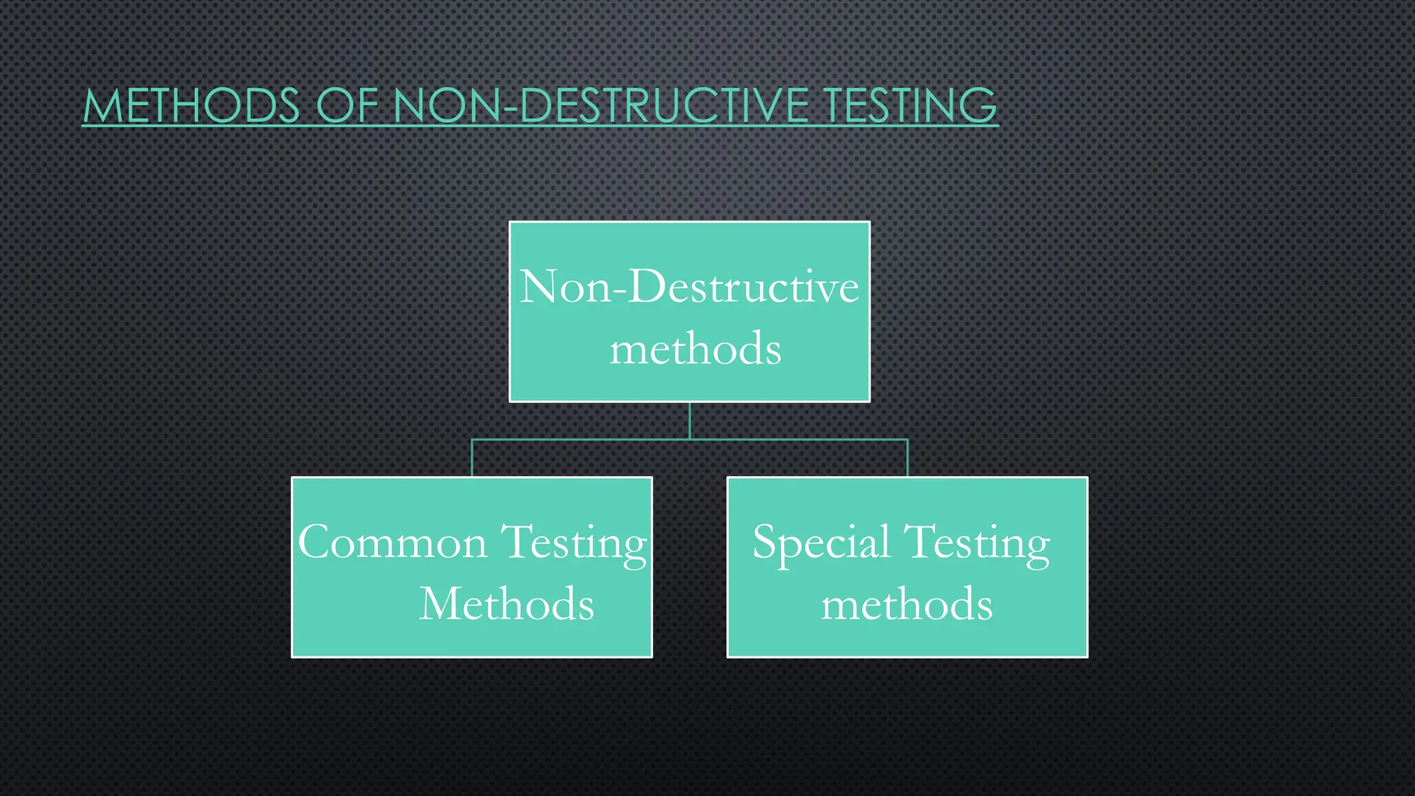
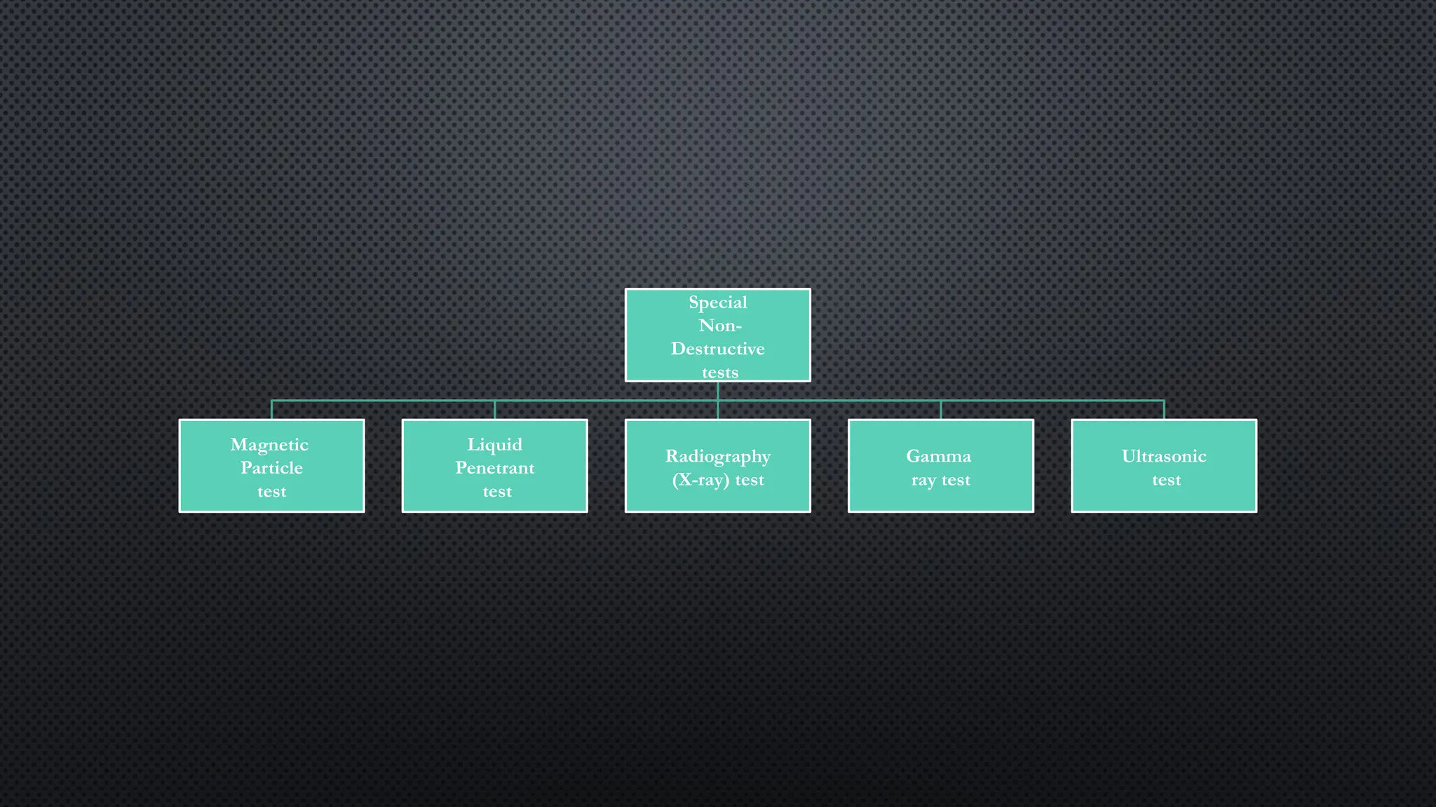
METHODS OF NON-DESTRUCTIVETESTING
Non-Destructive
methods
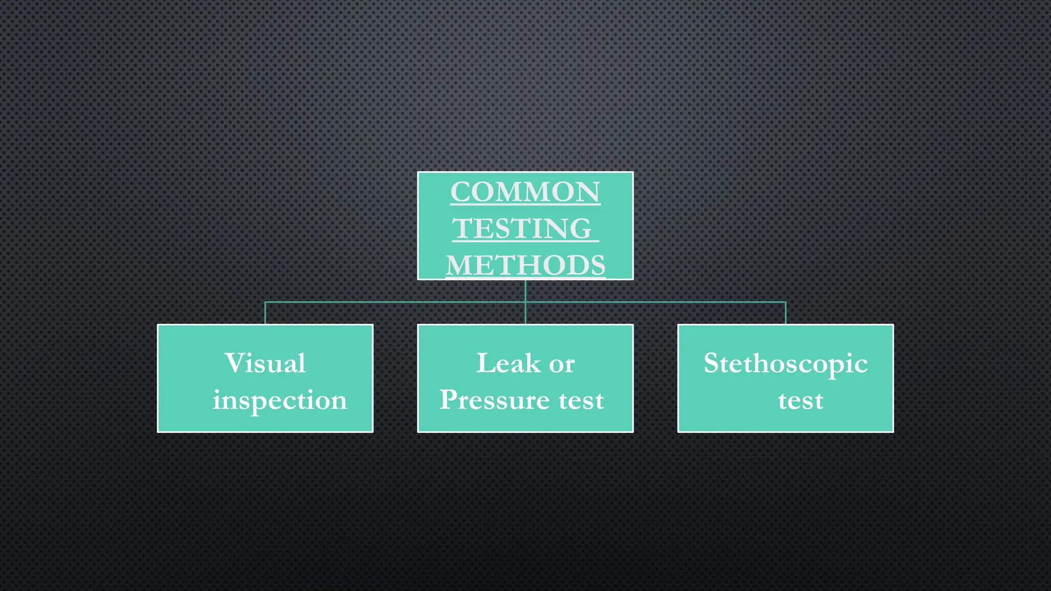
Common Testing
Methods
Special Testing
methods
VISUAL INSPECTION
• ITIS THE SIMPLEST, FASTEST, THE MOST ECONOMICAL AND MOST
COMMONLY USED METHOD FOR DETECTING DEFECTS ON THE
SURFACE OF THE WELD.
• VISUAL INSPECTION MAY BE CARRIED OUT IN THREE STAGES:
• (I) BEFORE WELDING
• (II) DURING WELDING
• (III) AFTER WELDING
112.
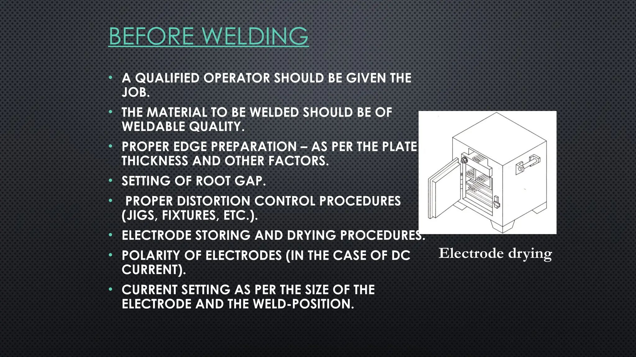
BEFORE WELDING
• AQUALIFIED OPERATOR SHOULD BE GIVEN THE
JOB.
• THE MATERIAL TO BE WELDED SHOULD BE OF
WELDABLE QUALITY.
• PROPER EDGE PREPARATION – AS PER THE PLATE
THICKNESS AND OTHER FACTORS.
• SETTING OF ROOT GAP.
• PROPER DISTORTION CONTROL PROCEDURES
(JIGS, FIXTURES, ETC.).
• ELECTRODE STORING AND DRYING PROCEDURES.
• POLARITY OF ELECTRODES (IN THE CASE OF DC
CURRENT).
• CURRENT SETTING AS PER THE SIZE OF THE
ELECTRODE AND THE WELD-POSITION.
Electrode drying
113.
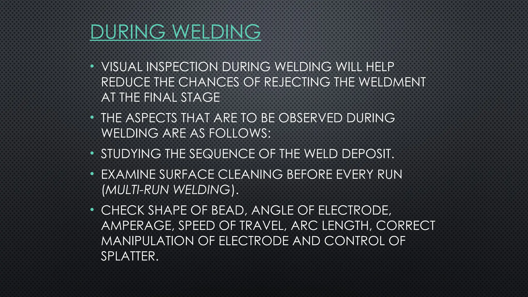
DURING WELDING
• VISUALINSPECTION DURING WELDING WILL HELP
REDUCE THE CHANCES OF REJECTING THE WELDMENT
AT THE FINAL STAGE
• THE ASPECTS THAT ARE TO BE OBSERVED DURING
WELDING ARE AS FOLLOWS:
• STUDYING THE SEQUENCE OF THE WELD DEPOSIT.
• EXAMINE SURFACE CLEANING BEFORE EVERY RUN
(MULTI-RUN WELDING).
• CHECK SHAPE OF BEAD, ANGLE OF ELECTRODE,
AMPERAGE, SPEED OF TRAVEL, ARC LENGTH, CORRECT
MANIPULATION OF ELECTRODE AND CONTROL OF
SPLATTER.
114.
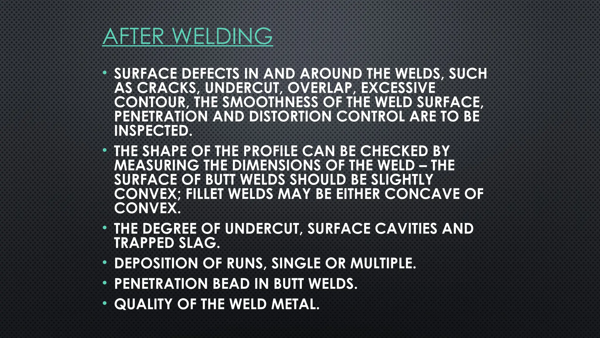
AFTER WELDING
• SURFACEDEFECTS IN AND AROUND THE WELDS, SUCH
AS CRACKS, UNDERCUT, OVERLAP, EXCESSIVE
CONTOUR, THE SMOOTHNESS OF THE WELD SURFACE,
PENETRATION AND DISTORTION CONTROL ARE TO BE
INSPECTED.
• THE SHAPE OF THE PROFILE CAN BE CHECKED BY
MEASURING THE DIMENSIONS OF THE WELD – THE
SURFACE OF BUTT WELDS SHOULD BE SLIGHTLY
CONVEX; FILLET WELDS MAY BE EITHER CONCAVE OF
CONVEX.
• THE DEGREE OF UNDERCUT, SURFACE CAVITIES AND
TRAPPED SLAG.
• DEPOSITION OF RUNS, SINGLE OR MULTIPLE.
• PENETRATION BEAD IN BUTT WELDS.
• QUALITY OF THE WELD METAL.
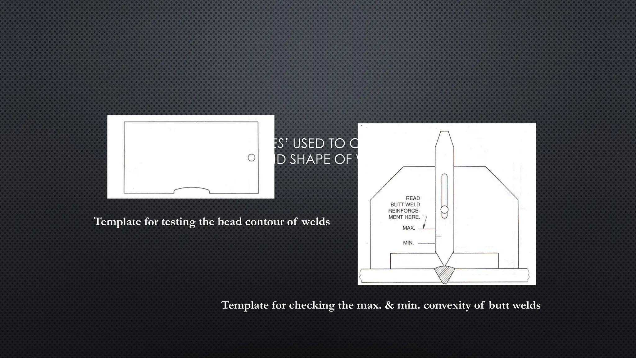
115.
• SOME OFTHE ‘TEMPLATES’ USED TO CHECK WELD PROFILES
AND DETERMINE SIZE AND SHAPE OF WELDS ARE SHOWN
BELOW :-
Template for testing the bead contour of welds
Template for checking the max. & min. convexity of butt welds
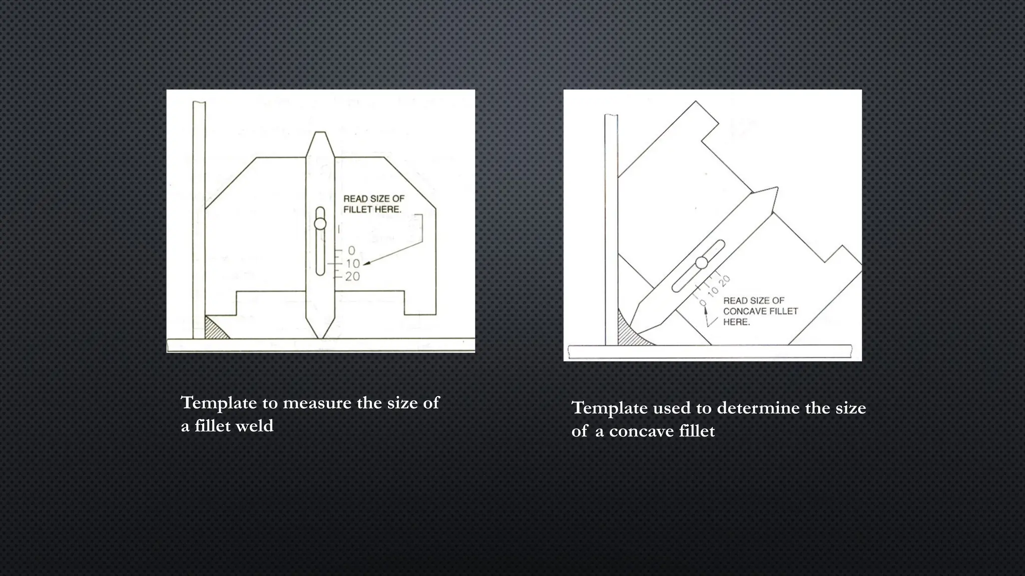
116.
Template to measurethe size of
a fillet weld
Template used to determine the size
of a concave fillet
117.
LEAK OR PRESSURETESTS
• THIS TEST IS USED TO TEST WELDED PRESSURE
VESSELS, TANKS AND PIPELINES FOR LEAKS.
• THE WELDED VESSEL IS SEALED AND SUBJECTED TO
INTERNAL PRESSURE USING AIR, WATER OR
KEROSENE. THE INTERNAL PRESSURE BUILT-UP
DEPENDS ON THE WORKING PRESSURE OF THE
JOINT, GENERALLY, TWICE THE WORKING PRESSURE
OF THE VESSEL.
• ANY DROP IN PRESSURE WOULD INDICATE A LEAK
OR LEAKS.
• SOAP SOLUTION MAY BE APPLIED TO CHECK FOR
LEAKS IN AN AIR-PRESSURE TEST.
118.
STETHOSCOPIC TEST:
• THEPRINCIPLE OF THIS TEST IS THAT A DEFECT-FREE WELD METAL
GIVES A GOOD RINGING SOUND WHEN STRUCK WITH A
HAMMER, WHEREAS THAT WITH DEFECTS GIVES A FLAT SOUND.
• AN ORDINARY PHYSICIAN’S STETHOSCOPE AND A HAMMER
MAY BE USED TO MAGNIFY AND IDENTIFY THE SOUND
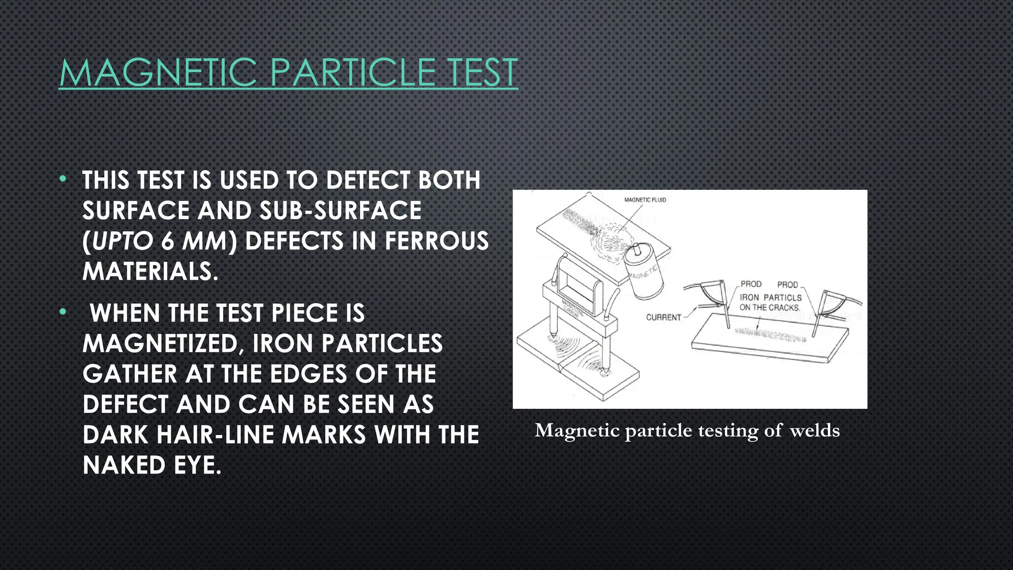
MAGNETIC PARTICLE TEST
•THIS TEST IS USED TO DETECT BOTH
SURFACE AND SUB-SURFACE
(UPTO 6 MM) DEFECTS IN FERROUS
MATERIALS.
• WHEN THE TEST PIECE IS
MAGNETIZED, IRON PARTICLES
GATHER AT THE EDGES OF THE
DEFECT AND CAN BE SEEN AS
DARK HAIR-LINE MARKS WITH THE
NAKED EYE.
Magnetic particle testing of welds
121.
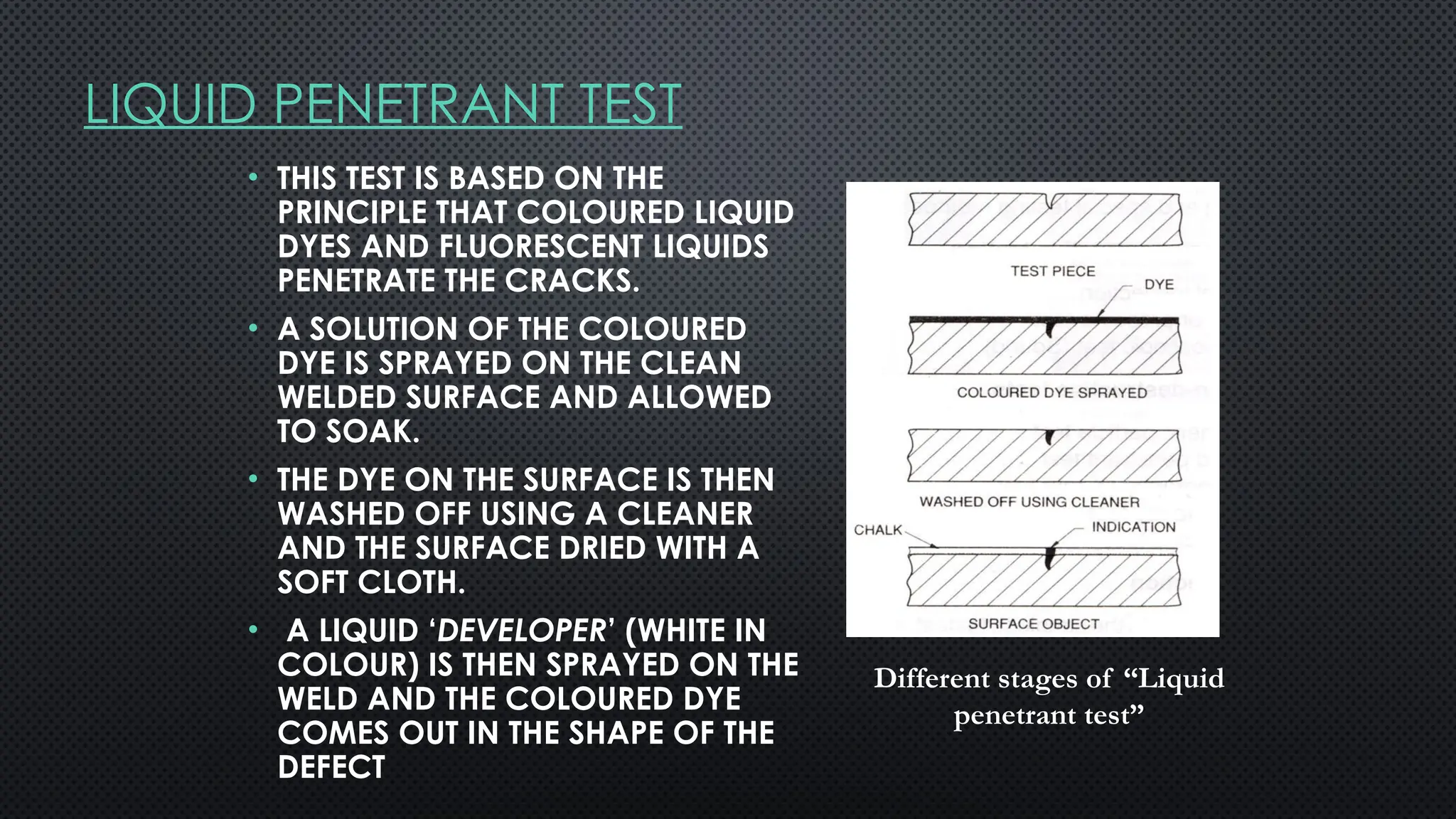
LIQUID PENETRANT TEST
•THIS TEST IS BASED ON THE
PRINCIPLE THAT COLOURED LIQUID
DYES AND FLUORESCENT LIQUIDS
PENETRATE THE CRACKS.
• A SOLUTION OF THE COLOURED
DYE IS SPRAYED ON THE CLEAN
WELDED SURFACE AND ALLOWED
TO SOAK.
• THE DYE ON THE SURFACE IS THEN
WASHED OFF USING A CLEANER
AND THE SURFACE DRIED WITH A
SOFT CLOTH.
• A LIQUID ‘DEVELOPER’ (WHITE IN
COLOUR) IS THEN SPRAYED ON THE
WELD AND THE COLOURED DYE
COMES OUT IN THE SHAPE OF THE
DEFECT
Different stages of “Liquid
penetrant test”
122.
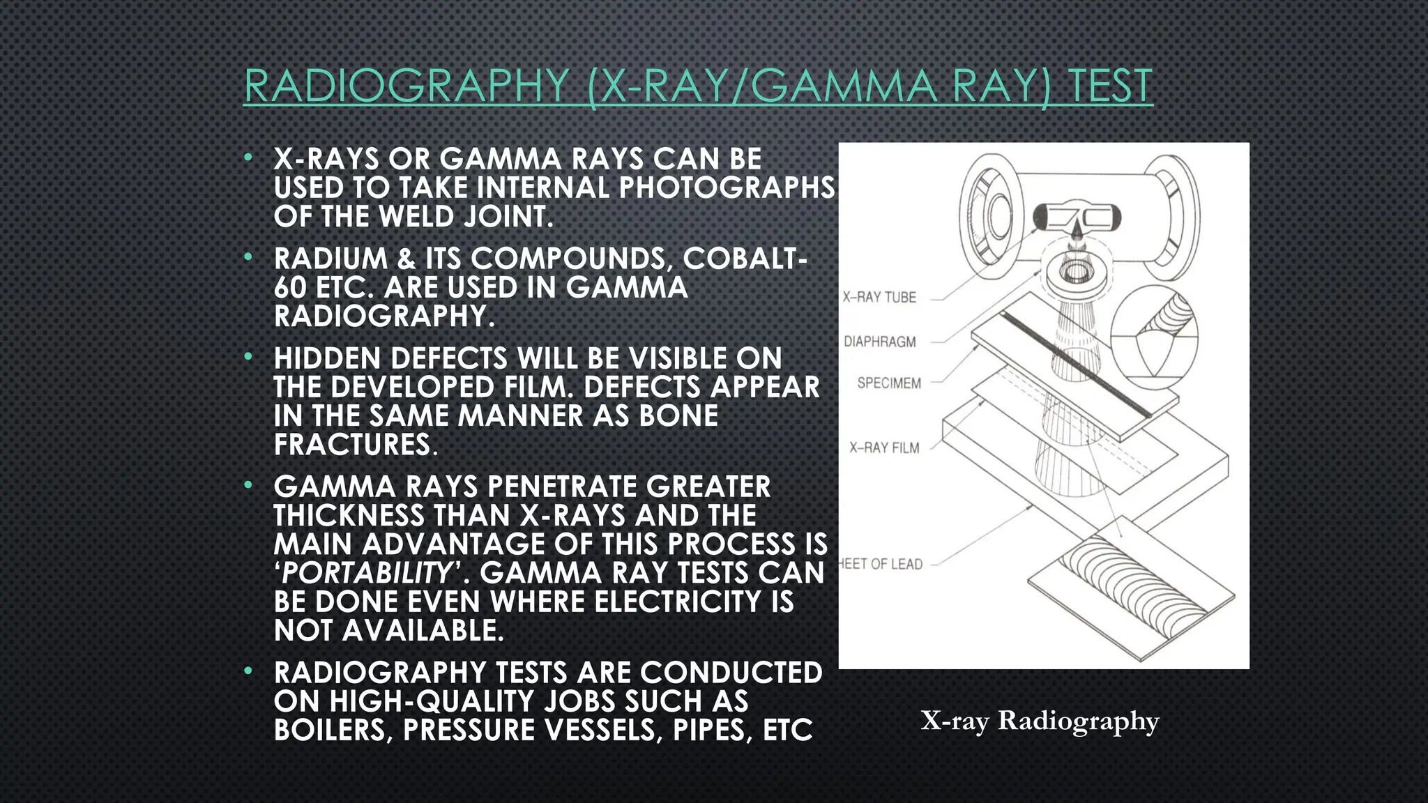
RADIOGRAPHY (X-RAY/GAMMA RAY)TEST
• X-RAYS OR GAMMA RAYS CAN BE
USED TO TAKE INTERNAL PHOTOGRAPHS
OF THE WELD JOINT.
• RADIUM & ITS COMPOUNDS, COBALT-
60 ETC. ARE USED IN GAMMA
RADIOGRAPHY.
• HIDDEN DEFECTS WILL BE VISIBLE ON
THE DEVELOPED FILM. DEFECTS APPEAR
IN THE SAME MANNER AS BONE
FRACTURES.
• GAMMA RAYS PENETRATE GREATER
THICKNESS THAN X-RAYS AND THE
MAIN ADVANTAGE OF THIS PROCESS IS
‘PORTABILITY’. GAMMA RAY TESTS CAN
BE DONE EVEN WHERE ELECTRICITY IS
NOT AVAILABLE.
• RADIOGRAPHY TESTS ARE CONDUCTED
ON HIGH-QUALITY JOBS SUCH AS
BOILERS, PRESSURE VESSELS, PIPES, ETC X-ray Radiography
123.
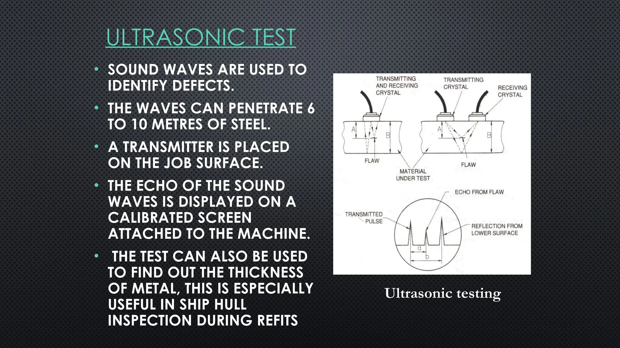
ULTRASONIC TEST
• SOUNDWAVES ARE USED TO
IDENTIFY DEFECTS.
• THE WAVES CAN PENETRATE 6
TO 10 METRES OF STEEL.
• A TRANSMITTER IS PLACED
ON THE JOB SURFACE.
• THE ECHO OF THE SOUND
WAVES IS DISPLAYED ON A
CALIBRATED SCREEN
ATTACHED TO THE MACHINE.
• THE TEST CAN ALSO BE USED
TO FIND OUT THE THICKNESS
OF METAL, THIS IS ESPECIALLY
USEFUL IN SHIP HULL
INSPECTION DURING REFITS
Ultrasonic testing
#8 Welding: is union between 2 material caused by heat or/ and pressure.
Joint: is a configuration of members. The junction of members or the edges of members which are to be joined or have been joined.
Weld root: The position in a prepared butt joint where the parts to be jointed are nearest together or in a square butt joint, the edges of the fusion faces which are further from the faces of the intended weld or in a fillet weld, the apex of the angle formed by the two fusion faces.
Root Face: The surface formed by the “squaring off” of the root edge of the fusion face to avoid a sharp edge at the root of the preparation.
Fusion zone: The depth to which the parent material has been fused.
Fusion boundary: in a weldment, the interface between weld material and base material, or between base material parts when filler material is not used.
Heat Affected Zone (HAZ): The part of the parent material where the properties have been changed by the heat of welding or cutting but not melted.
Weld Face: The surface of a weld seen from the side from which the weld was made.
Butt welding: Remove some material to get access for the welding whatever you take off have to be put back. Single ( efficiency and Cost) but Double ( to control distribution pressure).
Single V is the most common one 90% used for pipes and tubes.
Double V is second common one used for plates or heavy walls.
Convex is the most common in fillet used for pipe supports and structure work.
Spot: most common in resisting used in sheet material and electrical panel.
#46 MIG: Metal Inert Gas.
MAG: Metal Active Gas
In this process, coalescence is produced by heating metals with an arc between a continuous filler metal (consumable) electrode and the workpiece. The arc, electrode tip and molten weld metal are shielded from the atmosphere by a gas. Shielding is obtained entirely from an externally supplied inert gas, gas mixture, or a mixture o f a gas and a flux. The electrode wire for MIG welding is continuously fed into the arc and deposited as weld metal.
#107 Mechanical: Describes the action of force and motion.
Properties: something that makes one material deferent from another.
Hardness Test: The ability of a material to resist indentation. Diamond or steel ball to be used to form an indentation.
Toughness Test: The ability of a material to absorb impact energy. Test types are Charpy V, Izod, and Crack tip opening displacement.
Ductility ( Elongation %): The ability to deform under tensile force. Tensile Strength: The ability to resist a pulling force. The test show the yield point and tensile strength.
Non destructive test is used to check beyond visual inspection limitation
Penetrate Testing: check surface cracks, and leak in weldment. There are two types colour contrast and fluorescent penetrate. It consist of penetrant, and developer.
Magnetic Particle Testing: Check surface defects, especially surface cracks.It can show also subsurface imperfections. It consist of contrast, magnet - ink and magnetic field.
Ultrasonic Testing: Check surface and subsurface flaws including those too small to be detected by other tests. It consist of added couplant and CRT display unit and probe.
Radiographic Testing: Check internal flaws like cracks, porosity, blowholes, incomplete root penetration, inclusions, and burn through. Radiographic rays are two X rays ( from cathode ray tube C.R.T) and Gamma rays( from a radioactive isotope). It consist of prepared file, exposure to radioactive source the developed X ray film.
Radiographic test does not detect the wall side diffusion ( Ultrasonic test can detect that) it detect the defects in right angle.