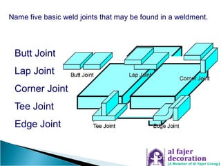
Welding Joint Design and
Welding Symbols
WORK DONE BY
RAJA K
MECHANICAL ENGINEER
(TEKLA STRUCTURES)
MOB :- +971 0558384955.
 After completing this chapter, you will be able to:
◦ Sketch the five basic welding joints
◦ Explain the factors that must be considered when
choosing a weld joint design
◦ Discuss the factors to consider when selecting a weld
joint design
◦ List and explain the information that can be included on a
welding symbol
◦ Sketch a welding symbol and identify the components
 Refers to the way pieces of metal are put together
or aligned with each other
◦ The five (5) basic weld joint designs are:
Butt Joint
Lap Joint
Corner Joint
Tee Joint
Edge Joint
Name five basic weld joints that may be found in a weldment.
Two ways of fitting up an outside corner joint.
Open Corner Closed Corner
NOTE: "fillet weld" = a triangular shaped weld in a corner
Name three types of joints that use fillet welds?
 Accessibility for welding
 Strength requirements
 Cyclic or static loading
 Material thickness
 Welding process to be used
 Material type
 Code Requirements
 Cost
Side Note: some considerations in selecting a type of joint to
use on a fabrication.
Bevel Groove Vee Groove
J Groove
U GrooveSquare Groove
Name two edge preparations used with butt joints.
Edge preparations used with butt joints.
More Important Groove Preparations:
Bevel Groove – single and double
Vee Groove – single and double
1
2
1 2 3
4
Single V Groove
Double V Groove
 Cost
◦ A number of items affect weld cost
Even a slight change in groove angle can save time and money.
 Weld Size
 Weld Faults
NOTE:
While Leg Size is the usual
method to specify and
measure weld size, the
Effective Throat is a more
accurate measure of fillet
weld strength!
Effective
Throat
Actual Throat
Leg Size2
Leg Size1
Theoretical
Throat
Convexity
¼
How is the size of a fillet determined and what is used to
measure it?
1. After selecting specified size
gauge from set, measure
Leg1
2. Measure Leg2
3. Verify throat with other side
of gauge (face of gauge
should touch weld)
L1
L2
3/8
How To Use A Fillet Gauge
 Undercut – most predominant
weld fault
◦ Fix: Short arc length, proper
amperage and speed
Describe four typical faults in single-pass horizontal fillet welds.
Other typical faults in single-pass horizontal fillet welds:
Porosity:
Lack of shielding gas
Wet electrode
Greasy material
Other typical faults in single-pass horizontal fillet welds:
Slag Inclusion: Improper cleaning / removal of slag
Porosity
Undercut
Poor Fitup
Lack of Penetration
F = Fillet
G = Groove
1 = Flat
2 = Horizontal
3 = Vertical
4 = Overhead
G = Groove
1 = Horizontal Rolled
2 = Vertical
5 = Horizontal Fixed
6 = 45 Incline
Welding Symbols
Welding Symbols (cont’d.)
3 parts of the welding symbol body:
Arrow
Reference Line
Tail
 Welding symbols
◦ Applied to reference
line at the base
 Reference lines have
an arrow side (near
side) and other side
(far side)
No size specified
What if the symbol
were on this side?
Sketch the weld required by this symbol.
As you see in this example,
the weld symbol usually
looks like the weld cross
section shape!
Symbol must be above
the reference line
indicating make weld on
"Other Side" of joint from
where arrow is pointing.
Complete the welding symbol that specifies the weld shown.
1/4
1/4 3/8
1/4
(1/4 x 3/8)
Nothing in the symbol specifies
unequal leg size location.
If there are not obvious reasons to put larger leg on one side of
joint (e.g. thicker metal), then it must be specified on drawing.
Complete the welding symbol that specifies the weld shown
including dimension specifications.
1/4
1/4
3/8
3/8
1/4
3/8
Complete the welding symbol that specifies the weld shown
including dimension specifications.
3/16
3/16
3/16 3 - 9
3/16
3 9
3/16
Sketch the weld required by this symbol including dimensions.
1/2
1/2 2 - 8
2 - 8
1/2
1/2
1/2
2 8
Sketch the weld required by this symbol including dimensions.
1/4
3/8
1 3
1 3
1/4 1 - 3
3/8 1 - 3
Complete the welding symbol that specifies the weld shown
including dimension specifications.
1/4
1/2
1/2
2 3 1/2
1/2 x 1/4 2 – 3 ½
1/2 x 1/4 2 – 3 ½
Complete the welding symbol that specifies the weld shown
including dimension specifications.
GTAW
1/8
Process:
Contour:
Finishing Method:
1/8
"TIG"
Flat
Welding
NOTE: The “Weld All Around”
symbol is not required for
pipe weld connections but
may be included for clarity
In other cases, it is needed
to specify that requirement
Sketch the weld required by this symbol including dimensions
and notes.
GTAW
1/8
Process:
Contour:
Finishing Method:
1/8
"TIG"
Flat
Welding
NOTE: The “Flag” symbol.
Indicates field weld or on-site welding
Sketch the weld required by this symbol including dimensions
and notes.
NOTE: The broken arrow line should be used
to point at the side to be prepared.
NOTE: The vertical line must
always be on the left side.
Complete the welding symbol that specifies the weld shown.
40
3/8
3/8
40°
Complete the welding symbol that specifies the weld shown
including dimension specifications.
Process:
Contour:
Finishing Method:
1/4
FCAW
1/4 G
Flux Cored
Arc Welding
Convex
Grinding
Sketch the weld required by this symbol including dimensions
and notes.
3/16
3/16
NOTE: Efforts should be made to avoid
Hi/Lows for a smooth surface
SURFACING FUNCTIONS:
 Buildup
 Stainless Overlay
 Abrasion Resistant Overlay
Sketch the weld required by this symbol including dimensions.
2
1/8
1/8 2
Complete the welding symbol that specifies the weld shown
including dimension specifications.
1 1/4
1/8
45
3/8 (1/2)
3/8
1/2
SMAW
FCAW
SMAW
3/8
1/8
45°
13/8
1/2
2 3
Sketch the weld required by this symbol including dimensions.
THE END
THANK YOU
WORK DONE BY
RAJA K
MECHANICAL ENGINEER
(TEKLA STRUCTURES)
MOB :- +971 0558384955.

WELDING JOINT DESING AND WELDINGSYMBOLS

  • 1.
    Welding Joint Designand Welding Symbols WORK DONE BY RAJA K MECHANICAL ENGINEER (TEKLA STRUCTURES) MOB :- +971 0558384955.
  • 2.
     After completingthis chapter, you will be able to: ◦ Sketch the five basic welding joints ◦ Explain the factors that must be considered when choosing a weld joint design ◦ Discuss the factors to consider when selecting a weld joint design ◦ List and explain the information that can be included on a welding symbol ◦ Sketch a welding symbol and identify the components
  • 3.
     Refers tothe way pieces of metal are put together or aligned with each other ◦ The five (5) basic weld joint designs are:
  • 4.
    Butt Joint Lap Joint CornerJoint Tee Joint Edge Joint Name five basic weld joints that may be found in a weldment.
  • 6.
    Two ways offitting up an outside corner joint. Open Corner Closed Corner
  • 7.
    NOTE: "fillet weld"= a triangular shaped weld in a corner Name three types of joints that use fillet welds?
  • 8.
     Accessibility forwelding  Strength requirements  Cyclic or static loading  Material thickness  Welding process to be used  Material type  Code Requirements  Cost Side Note: some considerations in selecting a type of joint to use on a fabrication.
  • 9.
    Bevel Groove VeeGroove J Groove U GrooveSquare Groove Name two edge preparations used with butt joints.
  • 10.
    Edge preparations usedwith butt joints.
  • 11.
    More Important GroovePreparations: Bevel Groove – single and double Vee Groove – single and double
  • 12.
    1 2 1 2 3 4 SingleV Groove Double V Groove
  • 13.
     Cost ◦ Anumber of items affect weld cost Even a slight change in groove angle can save time and money.
  • 14.
     Weld Size Weld Faults
  • 15.
    NOTE: While Leg Sizeis the usual method to specify and measure weld size, the Effective Throat is a more accurate measure of fillet weld strength! Effective Throat Actual Throat Leg Size2 Leg Size1 Theoretical Throat Convexity ¼ How is the size of a fillet determined and what is used to measure it?
  • 16.
    1. After selectingspecified size gauge from set, measure Leg1 2. Measure Leg2 3. Verify throat with other side of gauge (face of gauge should touch weld) L1 L2 3/8 How To Use A Fillet Gauge
  • 17.
     Undercut –most predominant weld fault ◦ Fix: Short arc length, proper amperage and speed
  • 18.
    Describe four typicalfaults in single-pass horizontal fillet welds.
  • 19.
    Other typical faultsin single-pass horizontal fillet welds: Porosity: Lack of shielding gas Wet electrode Greasy material
  • 20.
    Other typical faultsin single-pass horizontal fillet welds: Slag Inclusion: Improper cleaning / removal of slag
  • 21.
  • 22.
    F = Fillet G= Groove 1 = Flat 2 = Horizontal 3 = Vertical 4 = Overhead
  • 23.
    G = Groove 1= Horizontal Rolled 2 = Vertical 5 = Horizontal Fixed 6 = 45 Incline
  • 24.
  • 26.
    Welding Symbols (cont’d.) 3parts of the welding symbol body: Arrow Reference Line Tail
  • 27.
     Welding symbols ◦Applied to reference line at the base  Reference lines have an arrow side (near side) and other side (far side)
  • 28.
    No size specified Whatif the symbol were on this side? Sketch the weld required by this symbol.
  • 29.
    As you seein this example, the weld symbol usually looks like the weld cross section shape! Symbol must be above the reference line indicating make weld on "Other Side" of joint from where arrow is pointing. Complete the welding symbol that specifies the weld shown.
  • 30.
    1/4 1/4 3/8 1/4 (1/4 x3/8) Nothing in the symbol specifies unequal leg size location. If there are not obvious reasons to put larger leg on one side of joint (e.g. thicker metal), then it must be specified on drawing. Complete the welding symbol that specifies the weld shown including dimension specifications.
  • 31.
    1/4 1/4 3/8 3/8 1/4 3/8 Complete the weldingsymbol that specifies the weld shown including dimension specifications.
  • 32.
    3/16 3/16 3/16 3 -9 3/16 3 9 3/16 Sketch the weld required by this symbol including dimensions.
  • 33.
    1/2 1/2 2 -8 2 - 8 1/2 1/2 1/2 2 8 Sketch the weld required by this symbol including dimensions.
  • 34.
    1/4 3/8 1 3 1 3 1/41 - 3 3/8 1 - 3 Complete the welding symbol that specifies the weld shown including dimension specifications.
  • 35.
    1/4 1/2 1/2 2 3 1/2 1/2x 1/4 2 – 3 ½ 1/2 x 1/4 2 – 3 ½ Complete the welding symbol that specifies the weld shown including dimension specifications.
  • 36.
    GTAW 1/8 Process: Contour: Finishing Method: 1/8 "TIG" Flat Welding NOTE: The“Weld All Around” symbol is not required for pipe weld connections but may be included for clarity In other cases, it is needed to specify that requirement Sketch the weld required by this symbol including dimensions and notes.
  • 37.
    GTAW 1/8 Process: Contour: Finishing Method: 1/8 "TIG" Flat Welding NOTE: The“Flag” symbol. Indicates field weld or on-site welding Sketch the weld required by this symbol including dimensions and notes.
  • 38.
    NOTE: The brokenarrow line should be used to point at the side to be prepared. NOTE: The vertical line must always be on the left side. Complete the welding symbol that specifies the weld shown.
  • 39.
    40 3/8 3/8 40° Complete the weldingsymbol that specifies the weld shown including dimension specifications.
  • 40.
    Process: Contour: Finishing Method: 1/4 FCAW 1/4 G FluxCored Arc Welding Convex Grinding Sketch the weld required by this symbol including dimensions and notes.
  • 41.
    3/16 3/16 NOTE: Efforts shouldbe made to avoid Hi/Lows for a smooth surface SURFACING FUNCTIONS:  Buildup  Stainless Overlay  Abrasion Resistant Overlay Sketch the weld required by this symbol including dimensions.
  • 42.
    2 1/8 1/8 2 Complete thewelding symbol that specifies the weld shown including dimension specifications.
  • 43.
    1 1/4 1/8 45 3/8 (1/2) 3/8 1/2 SMAW FCAW SMAW 3/8 1/8 45° 13/8 1/2 23 Sketch the weld required by this symbol including dimensions.
  • 44.
    THE END THANK YOU WORKDONE BY RAJA K MECHANICAL ENGINEER (TEKLA STRUCTURES) MOB :- +971 0558384955.