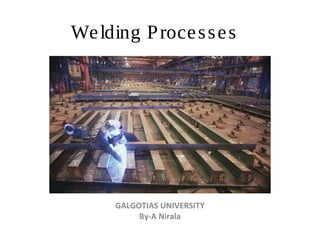
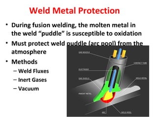
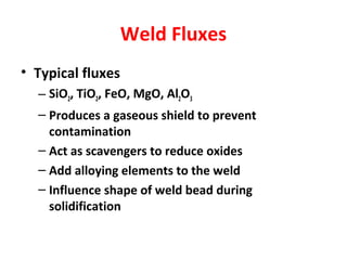
The document provides an overview of welding processes including:
- A brief history of welding from the late 19th century to modern times.
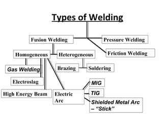
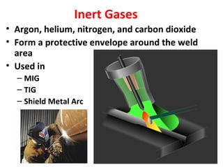
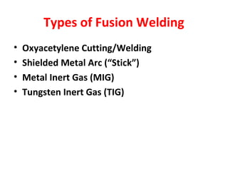
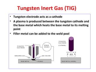
- The main types of welding including fusion welding, pressure welding, and specific processes like MIG, TIG, stick welding.
- Key factors that determine the weldability of metals including metallurgical capacity, mechanical soundness, and serviceability.
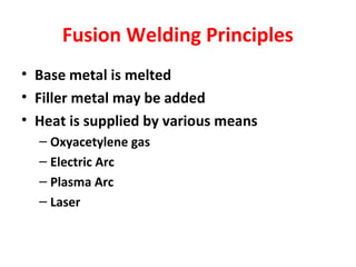
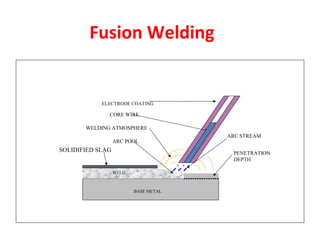
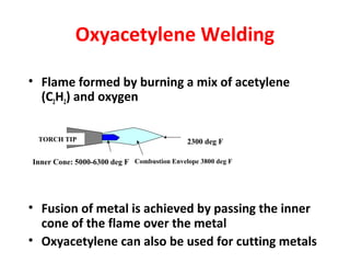
- Principles of fusion welding including melting the base metal and adding filler metal using heat sources like gas flames or electric arcs.