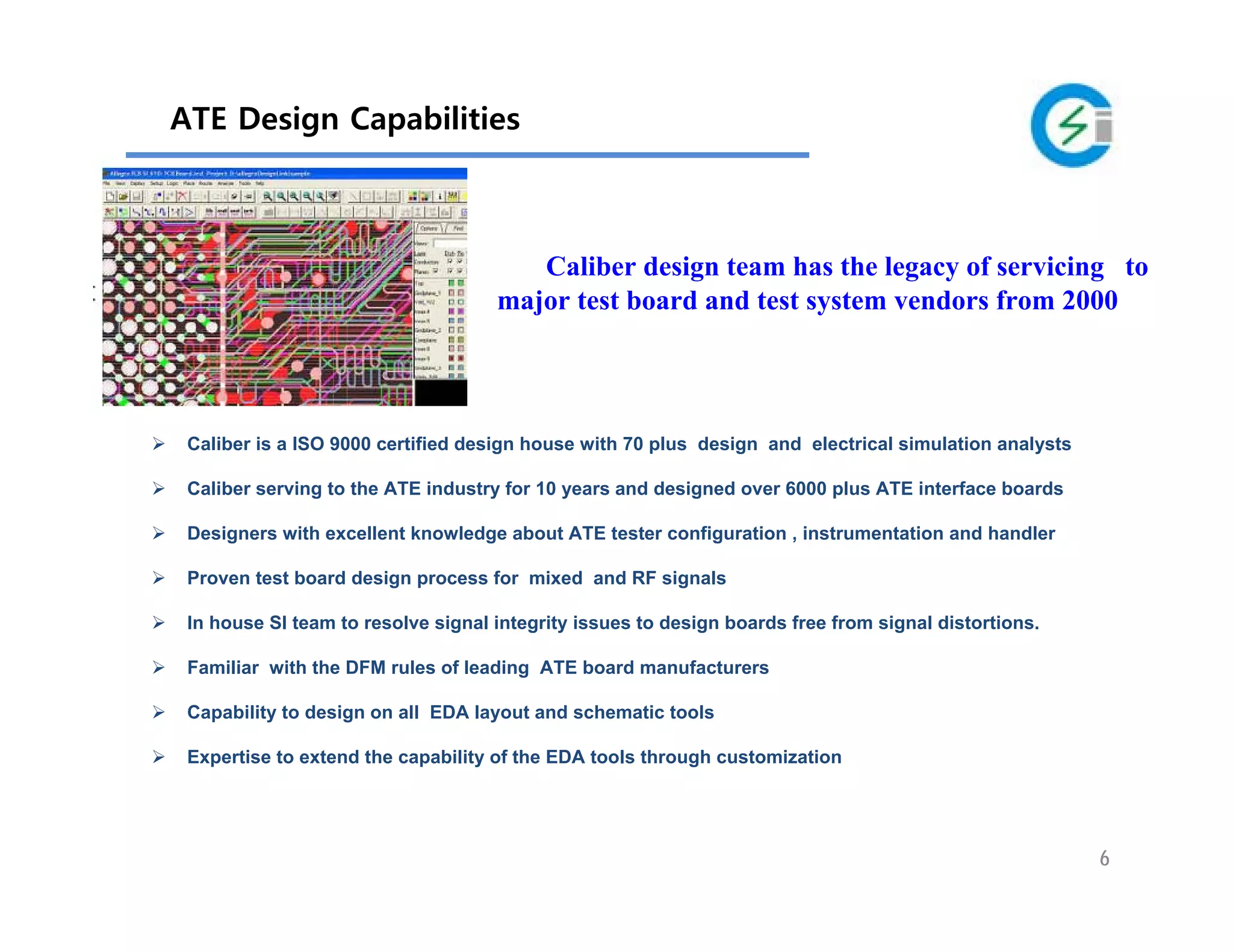
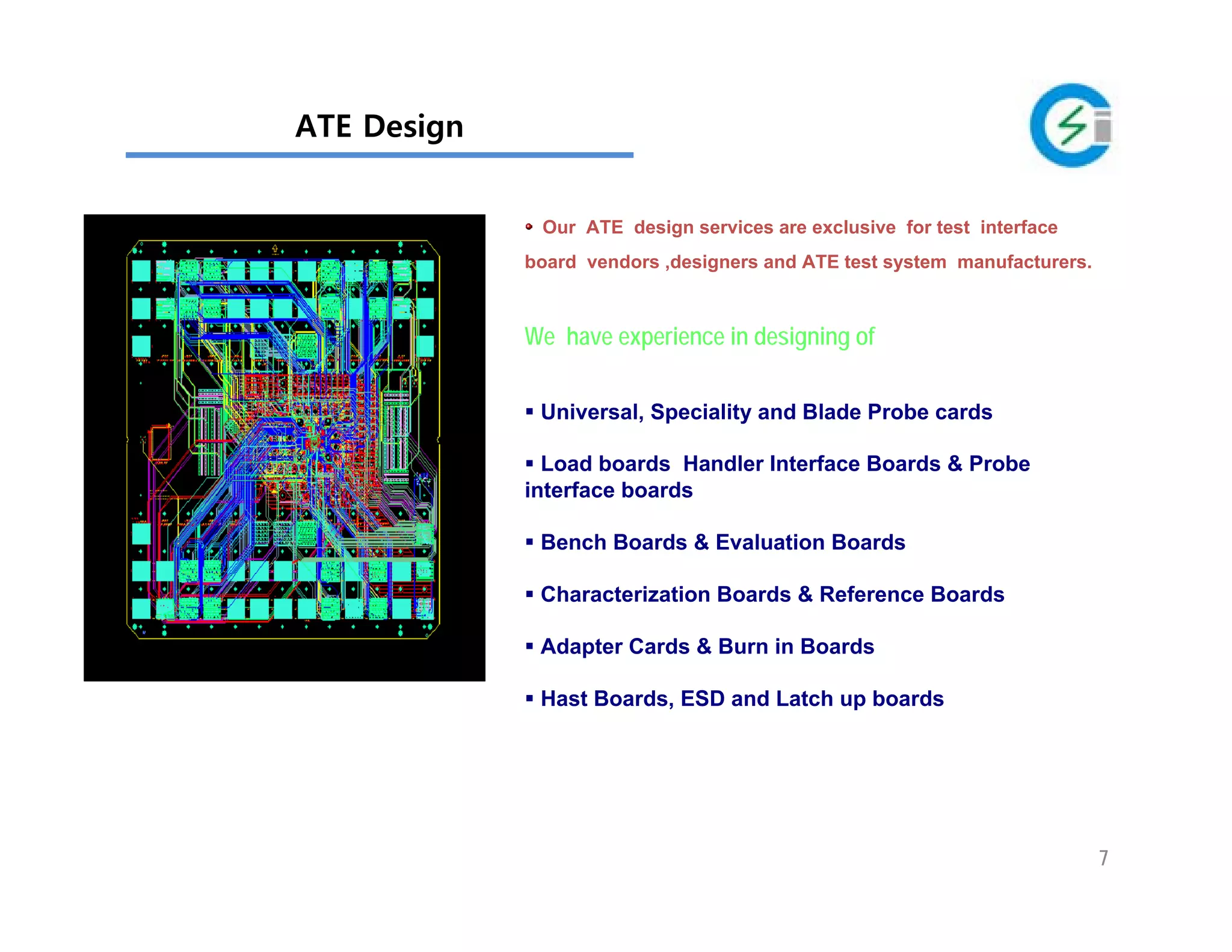
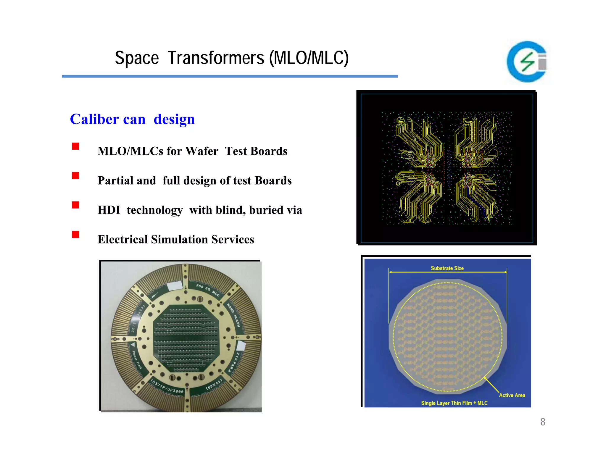
2010.10
1
Since 2000
Contact :
Caliber Interconnect Solution (Pvt) Ltd
No 6 ,1st Street, Kavundampalayam,
Coimbatore-30
India
www.caliberinterconnect.com
Design for perfection
ATE hardware Design/Routing and SI Analysis services
(Exclusive service to ATE Designers)
ATE Design Service EnvironmentATE Design Service Environment
Layout Tools
Cadence Allegro
Mentor Expedition
Mentor Pads
Zuken Cadstar
Protel DXP
Pcad
Schematic Tools
Concept HDL
Mentor Capture CIS
Dxdesigner
Orcad capture
Powerlogic
Testers
Advantest
Credence
LTX
Nextest
Verigy
Teradyne
Yokogawa
Service Introduction
Design/Routing/SI analysis support services to
ATE test interface board designing from 2000.
Designers are well versed with ATE test
system instrumentation and follows hardware
design guidelines recommended by test system
vendors.
3
“Provide the best solutions to the society by reapi
ng the benefits of advanced technologies.”
“Provide dependable services to the satisfaction of the
customers through innovation and commitment.”
VisionVision
MissionMission
Caliber is a design supplier to
ATE Test system vendors
Test interface board vendors and design
houses
Test houses and socket manufacturers
Probecard assembly and design houses
IC packaging design, manufacturing and
assembly houses
4
HistoryHistory
2000 Feb Caliber was registered
2004 Caliber licensed to Cadence tools and Signal integrity team formed.
Caliber become an ISO 9001:2000 certified design house.
2005 Caliber consolidated itself as a strong technological service provider in ATE
domain with 100 plus designers and customers around the globe
2006 Caliber developed test program conversion tools. Caliber formed 50 member
component library and data capturing team
2007 Caliber formed ATE test program development division
2010 Caliber licensed to Cadence PCB SI
Caliber qualified by Teradyne as a design service provider and a service
provider to another major test system vendor.
2001 Caliber developed EDA conversion and design tools for PCB designing .
ATE design team formed and started serving for major ATE vendors
2002 High speed design and component assembly team was formed
2003 Caliber entered into IC Package design service
5
Engineering Service Capabilities
Divisions
Design/Routing support for ATE test
hardware ,handles partial/full design and routing
alone services
ATE Design
MLO/MLC
SI Analysis
SiP
Library
HSD High speed application boards
Designing Substrates for vertical probecards
Signal and power integrity analysis services
for PCBs and Packages
IC Packaging BGA packages for ICs
System in Package designing
Component Library development and
maintenance
6
Caliber is a ISO 9000 certified design house with 70 plus design and electrical simulation analysts
Caliber serving to the ATE industry for 10 years and designed over 6000 plus ATE interface boards
Designers with excellent knowledge about ATE tester configuration , instrumentation and handler
Proven test board design process for mixed and RF signals
In house SI team to resolve signal integrity issues to design boards free from signal distortions.
Familiar with the DFM rules of leading ATE board manufacturers
Capability to design on all EDA layout and schematic tools
Expertise to extend the capability of the EDA tools through customization
ATE Design Capabilities
Caliber design team has the legacy of servicing to
major test board and test system vendors from 2000
7
ATE Design
Our ATE design services are exclusive for test interface
board vendors ,designers and ATE test system manufacturers.
We have experience in designing of
Universal, Speciality and Blade Probe cards
Load boards Handler Interface Boards & Probe
interface boards
Bench Boards & Evaluation Boards
Characterization Boards & Reference Boards
Adapter Cards & Burn in Boards
Hast Boards, ESD and Latch up boards
8
Space Transformers (MLO/MLC)
Caliber can design
MLO/MLCs for Wafer Test Boards
Partial and full design of test Boards
HDI technology with blind, buried via
Electrical Simulation Services
Electrical Integrity Analysis
The following electrical analysis are
carried out in the pre and post layout analysis:
Signal Integrity Analysis
Timing Analysis
Power Integrity Analysis
S-parameter Analysis
The test boards operating at high
frequency and fast switching rates demand
SI analysis for the right design for first pass
success. Our SI engineers are having strong
knowledge in SI theory and expertise in
simulation tools to analyze various SI issues.
Simulation of probcard PCB with MLO/MLC
11
Simulation Ability for ATE
Expertise in Simulation Tools
Allegro PCB SI
Allegro PCB PI
Allegro Package SI
Hyperlynx
HSpice
Controlled Impedance Calculation
Insertion and Return Loss Calculation
Interconnect Bandwidth verification
Reflection Analysis
Crosstalk Analysis
Power Plane IR-Drop Analysis
Power Plane Impedance Profile Analysis
Channel Analysis
What we simulate
12
Controlled Impedance Calculation
The Trace Width is calculated for Single ended signals and Trace
Width/Spacing for Differential Pairs to achieve controlled impedance of
50 ohms & 100 ohms respectively
13
Service HighlightsService Highlights
Get your test boards designed at Caliber
Caliber reduces your risk of investment on design infrastructure and resources
High quality boards designed at short duration for a low cost
Pool of experienced designers having experience in multiple EDA tools and
ATE Testers systems
Reduce your design time and increases the profit margin
Translator available for German ,French and Japanese.
Proven design process and quality assurance system
14
Controlled Impedance Calculation
The Trace Width is calculated for Single ended signals and Trace
Width/Spacing for Differential Pairs to achieve controlled impedance of
50 ohms & 100 ohms respectively
15
Insertion and Return Loss Calculation
The trace is modeled with a ground coupled via
Insertion loss @ 800 MHz = -0.787 dB (up to -1dB is good value)
Return loss @ 800 MHz = -16.003 dB (below -15dB is good value)
16
Interconnect Bandwidth verification
The band width (BW) of the interconnect is calculated
BW = 0.35/RT (This is thump rule from signal integrity theory)
RT = rise time for 10% to 90% signal level
RT =197 ps
BW = 0.35 / 197 ps
= 1.77 GHz
17
Reflection Analysis
The receiver waveform is not
crossing the threshold levels and
not good
18
Reflection Analysis
The receiver waveform is
crossing the threshold levels and
the waveform is good
19
Crosstalk Analysis
After Optimization :
HSEvenXtalk = 58.68 mV
LSOddXtalk = 64.71 mV
20
Crosstalk Analysis (Frequency domain)
The NEXT and FEXT analysis is carried out for Crosstalk analysis
1%
21
IRIR--Drop AnalysisDrop Analysis
The maximum voltage drop observed is 1.7 mV for 1.5V supply
The IR-Drop analysis of power plane
22
Power Plane Impedance AnalysisPower Plane Impedance Analysis
From 112 MHz (Actual) to 237 MHz (optimized)
23
Channel AnalysisChannel Analysis
6.25 Gbps Serial Data Transfer :
From eye height 0V (actual) to 269 mV(optimized)
24
Short DeliveryShort Delivery
Our team can route 1500-2000 traces in a day
Low complex designs 1-2 Days
Medium complex 2-4 Days
High Complex design 4-6 Days
We offer Signal and Power integrity simulation for test boards
Thank you
For more info please contact
sales@caliberinterconnect.com

ATE boards designs

  • 1.
    2010.10 1 Since 2000 Contact : CaliberInterconnect Solution (Pvt) Ltd No 6 ,1st Street, Kavundampalayam, Coimbatore-30 India www.caliberinterconnect.com Design for perfection ATE hardware Design/Routing and SI Analysis services (Exclusive service to ATE Designers)
  • 2.
    ATE Design ServiceEnvironmentATE Design Service Environment Layout Tools Cadence Allegro Mentor Expedition Mentor Pads Zuken Cadstar Protel DXP Pcad Schematic Tools Concept HDL Mentor Capture CIS Dxdesigner Orcad capture Powerlogic Testers Advantest Credence LTX Nextest Verigy Teradyne Yokogawa Service Introduction Design/Routing/SI analysis support services to ATE test interface board designing from 2000. Designers are well versed with ATE test system instrumentation and follows hardware design guidelines recommended by test system vendors.
  • 3.
    3 “Provide the bestsolutions to the society by reapi ng the benefits of advanced technologies.” “Provide dependable services to the satisfaction of the customers through innovation and commitment.” VisionVision MissionMission Caliber is a design supplier to ATE Test system vendors Test interface board vendors and design houses Test houses and socket manufacturers Probecard assembly and design houses IC packaging design, manufacturing and assembly houses
  • 4.
    4 HistoryHistory 2000 Feb Caliberwas registered 2004 Caliber licensed to Cadence tools and Signal integrity team formed. Caliber become an ISO 9001:2000 certified design house. 2005 Caliber consolidated itself as a strong technological service provider in ATE domain with 100 plus designers and customers around the globe 2006 Caliber developed test program conversion tools. Caliber formed 50 member component library and data capturing team 2007 Caliber formed ATE test program development division 2010 Caliber licensed to Cadence PCB SI Caliber qualified by Teradyne as a design service provider and a service provider to another major test system vendor. 2001 Caliber developed EDA conversion and design tools for PCB designing . ATE design team formed and started serving for major ATE vendors 2002 High speed design and component assembly team was formed 2003 Caliber entered into IC Package design service
  • 5.
    5 Engineering Service Capabilities Divisions Design/Routingsupport for ATE test hardware ,handles partial/full design and routing alone services ATE Design MLO/MLC SI Analysis SiP Library HSD High speed application boards Designing Substrates for vertical probecards Signal and power integrity analysis services for PCBs and Packages IC Packaging BGA packages for ICs System in Package designing Component Library development and maintenance
  • 6.
    6 Caliber is aISO 9000 certified design house with 70 plus design and electrical simulation analysts Caliber serving to the ATE industry for 10 years and designed over 6000 plus ATE interface boards Designers with excellent knowledge about ATE tester configuration , instrumentation and handler Proven test board design process for mixed and RF signals In house SI team to resolve signal integrity issues to design boards free from signal distortions. Familiar with the DFM rules of leading ATE board manufacturers Capability to design on all EDA layout and schematic tools Expertise to extend the capability of the EDA tools through customization ATE Design Capabilities Caliber design team has the legacy of servicing to major test board and test system vendors from 2000
  • 7.
    7 ATE Design Our ATEdesign services are exclusive for test interface board vendors ,designers and ATE test system manufacturers. We have experience in designing of Universal, Speciality and Blade Probe cards Load boards Handler Interface Boards & Probe interface boards Bench Boards & Evaluation Boards Characterization Boards & Reference Boards Adapter Cards & Burn in Boards Hast Boards, ESD and Latch up boards
  • 8.
    8 Space Transformers (MLO/MLC) Calibercan design MLO/MLCs for Wafer Test Boards Partial and full design of test Boards HDI technology with blind, buried via Electrical Simulation Services
  • 9.
    Electrical Integrity Analysis Thefollowing electrical analysis are carried out in the pre and post layout analysis: Signal Integrity Analysis Timing Analysis Power Integrity Analysis S-parameter Analysis The test boards operating at high frequency and fast switching rates demand SI analysis for the right design for first pass success. Our SI engineers are having strong knowledge in SI theory and expertise in simulation tools to analyze various SI issues.
  • 10.
    Simulation of probcardPCB with MLO/MLC
  • 11.
    11 Simulation Ability forATE Expertise in Simulation Tools Allegro PCB SI Allegro PCB PI Allegro Package SI Hyperlynx HSpice Controlled Impedance Calculation Insertion and Return Loss Calculation Interconnect Bandwidth verification Reflection Analysis Crosstalk Analysis Power Plane IR-Drop Analysis Power Plane Impedance Profile Analysis Channel Analysis What we simulate
  • 12.
    12 Controlled Impedance Calculation TheTrace Width is calculated for Single ended signals and Trace Width/Spacing for Differential Pairs to achieve controlled impedance of 50 ohms & 100 ohms respectively
  • 13.
    13 Service HighlightsService Highlights Getyour test boards designed at Caliber Caliber reduces your risk of investment on design infrastructure and resources High quality boards designed at short duration for a low cost Pool of experienced designers having experience in multiple EDA tools and ATE Testers systems Reduce your design time and increases the profit margin Translator available for German ,French and Japanese. Proven design process and quality assurance system
  • 14.
    14 Controlled Impedance Calculation TheTrace Width is calculated for Single ended signals and Trace Width/Spacing for Differential Pairs to achieve controlled impedance of 50 ohms & 100 ohms respectively
  • 15.
    15 Insertion and ReturnLoss Calculation The trace is modeled with a ground coupled via Insertion loss @ 800 MHz = -0.787 dB (up to -1dB is good value) Return loss @ 800 MHz = -16.003 dB (below -15dB is good value)
  • 16.
    16 Interconnect Bandwidth verification Theband width (BW) of the interconnect is calculated BW = 0.35/RT (This is thump rule from signal integrity theory) RT = rise time for 10% to 90% signal level RT =197 ps BW = 0.35 / 197 ps = 1.77 GHz
  • 17.
    17 Reflection Analysis The receiverwaveform is not crossing the threshold levels and not good
  • 18.
    18 Reflection Analysis The receiverwaveform is crossing the threshold levels and the waveform is good
  • 19.
    19 Crosstalk Analysis After Optimization: HSEvenXtalk = 58.68 mV LSOddXtalk = 64.71 mV
  • 20.
    20 Crosstalk Analysis (Frequencydomain) The NEXT and FEXT analysis is carried out for Crosstalk analysis 1%
  • 21.
    21 IRIR--Drop AnalysisDrop Analysis Themaximum voltage drop observed is 1.7 mV for 1.5V supply The IR-Drop analysis of power plane
  • 22.
    22 Power Plane ImpedanceAnalysisPower Plane Impedance Analysis From 112 MHz (Actual) to 237 MHz (optimized)
  • 23.
    23 Channel AnalysisChannel Analysis 6.25Gbps Serial Data Transfer : From eye height 0V (actual) to 269 mV(optimized)
  • 24.
    24 Short DeliveryShort Delivery Ourteam can route 1500-2000 traces in a day Low complex designs 1-2 Days Medium complex 2-4 Days High Complex design 4-6 Days We offer Signal and Power integrity simulation for test boards
  • 25.
    Thank you For moreinfo please contact sales@caliberinterconnect.com