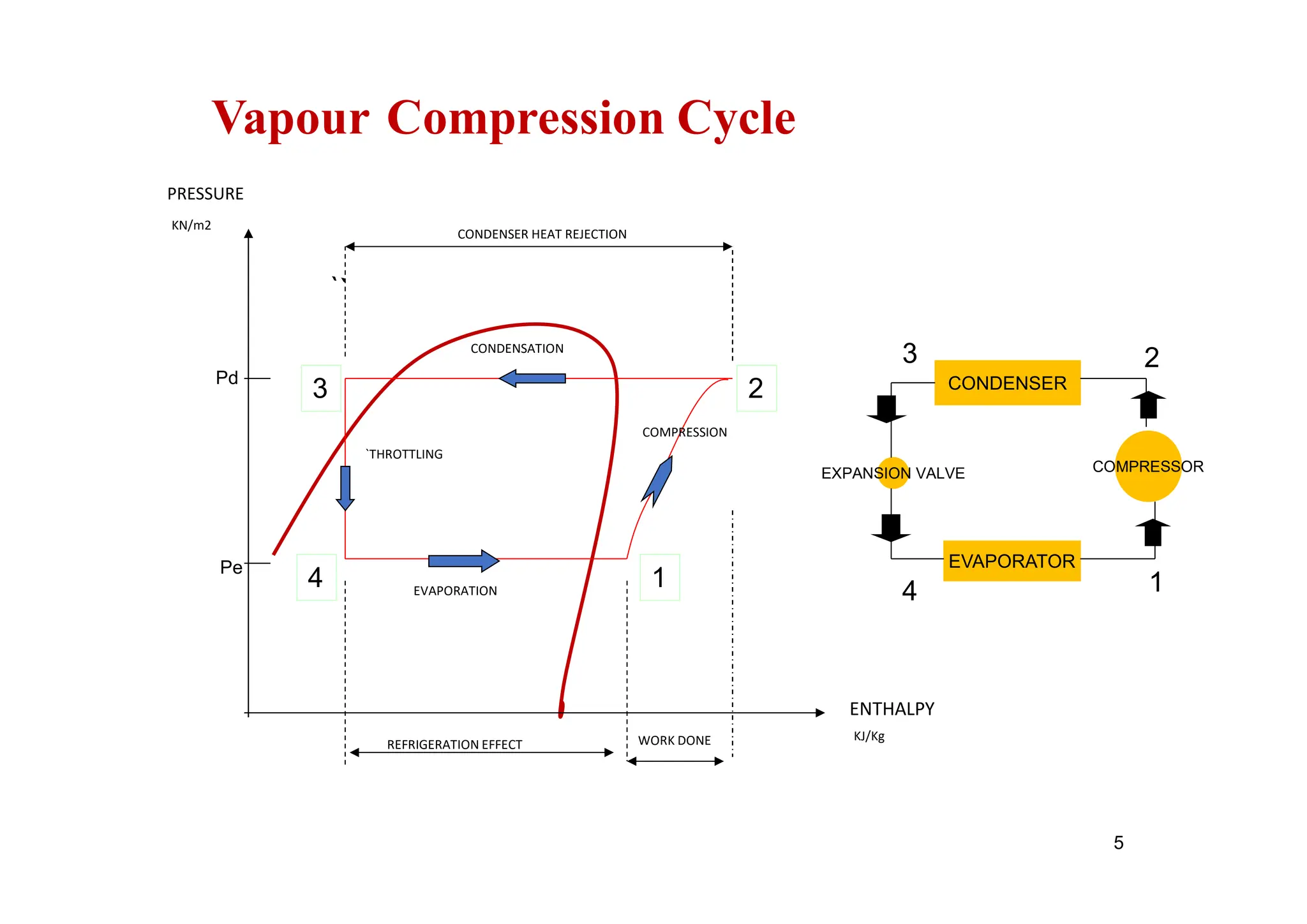
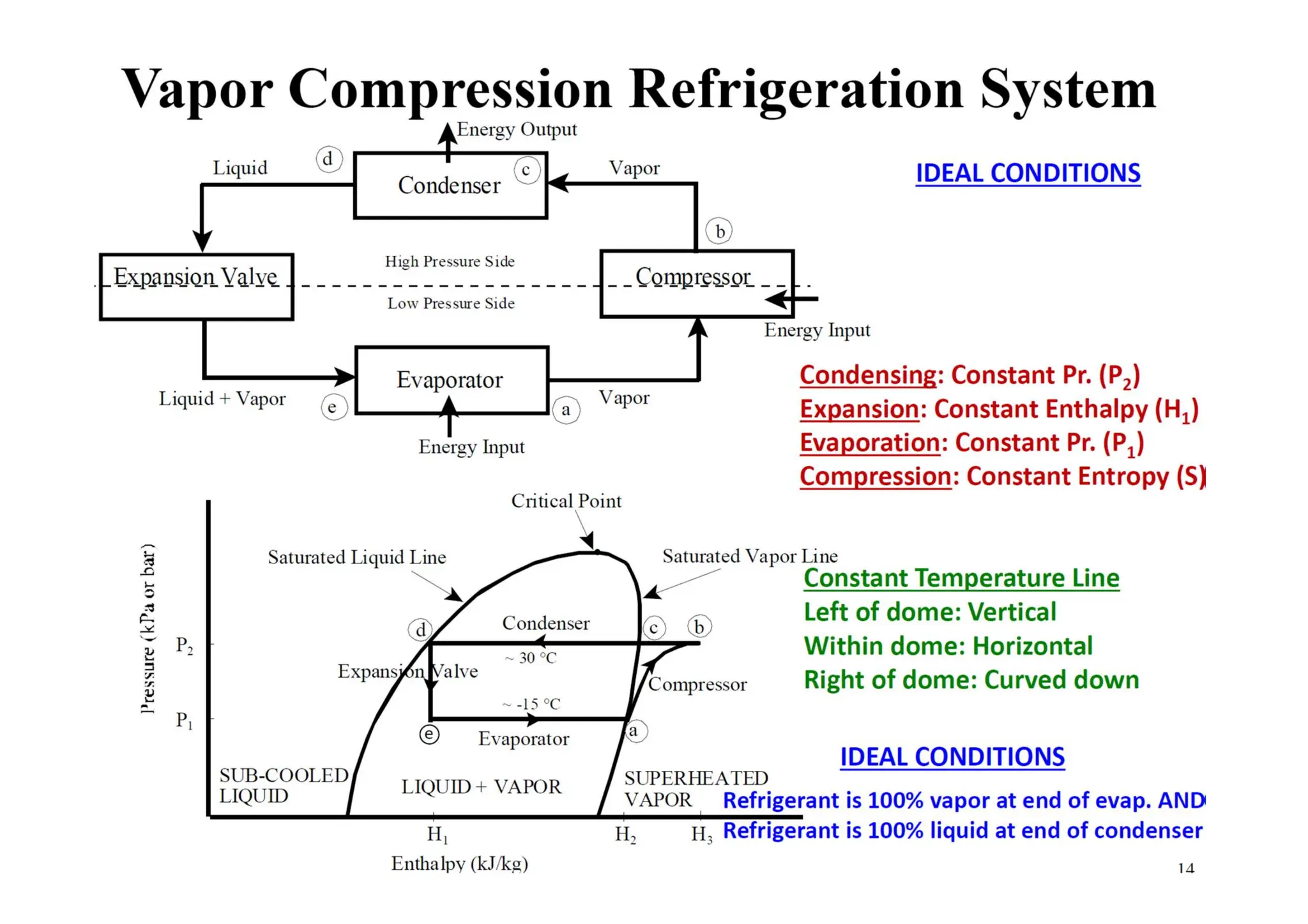
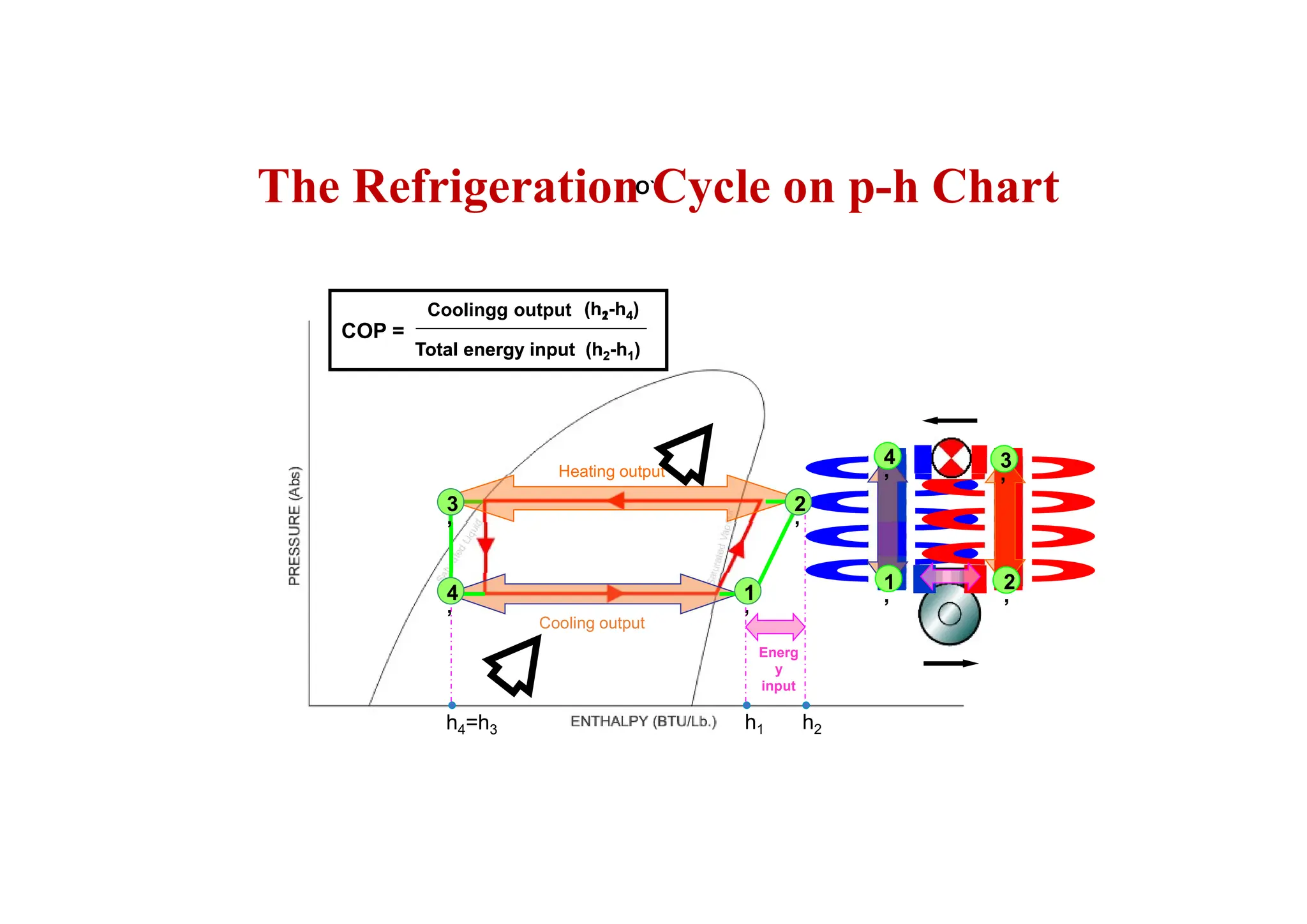
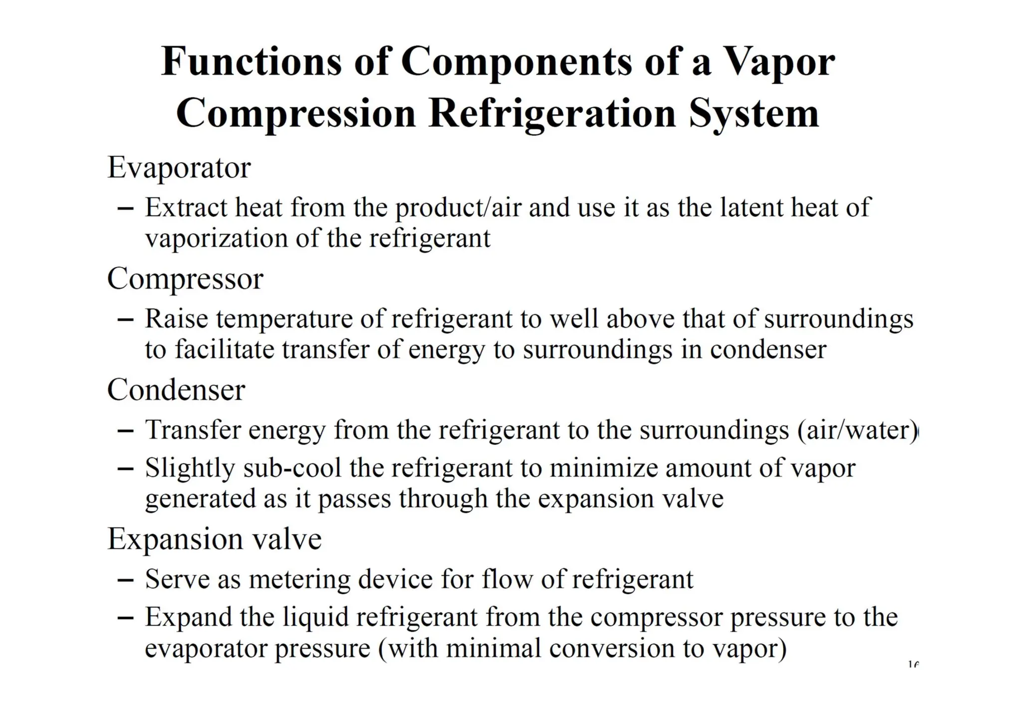
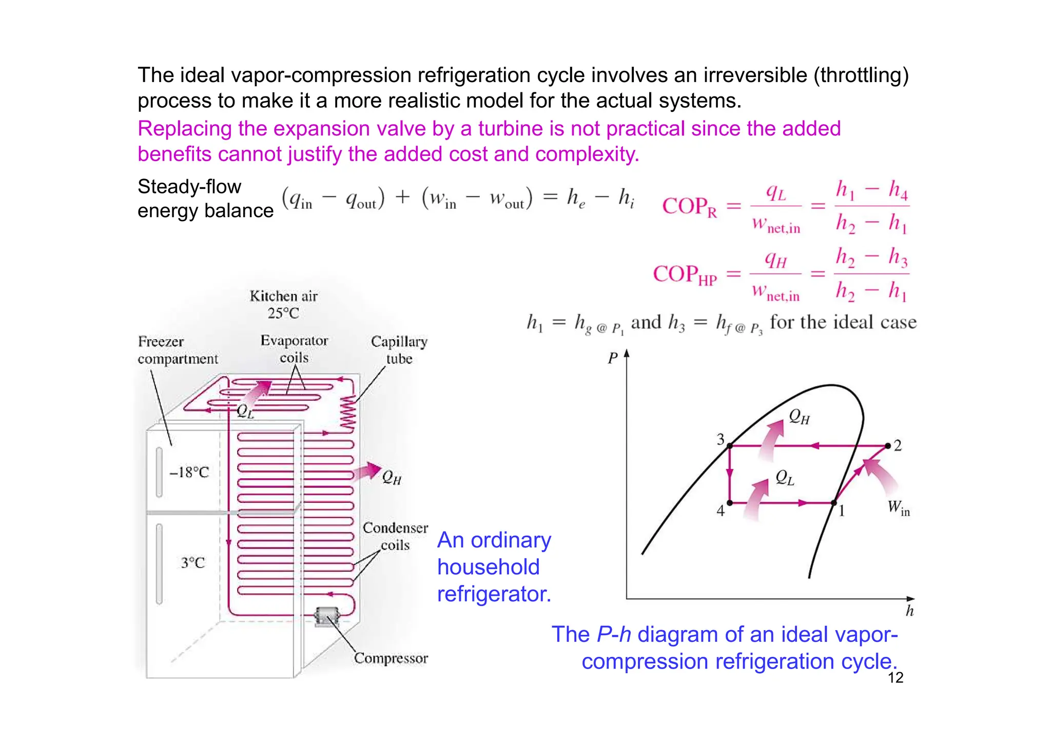
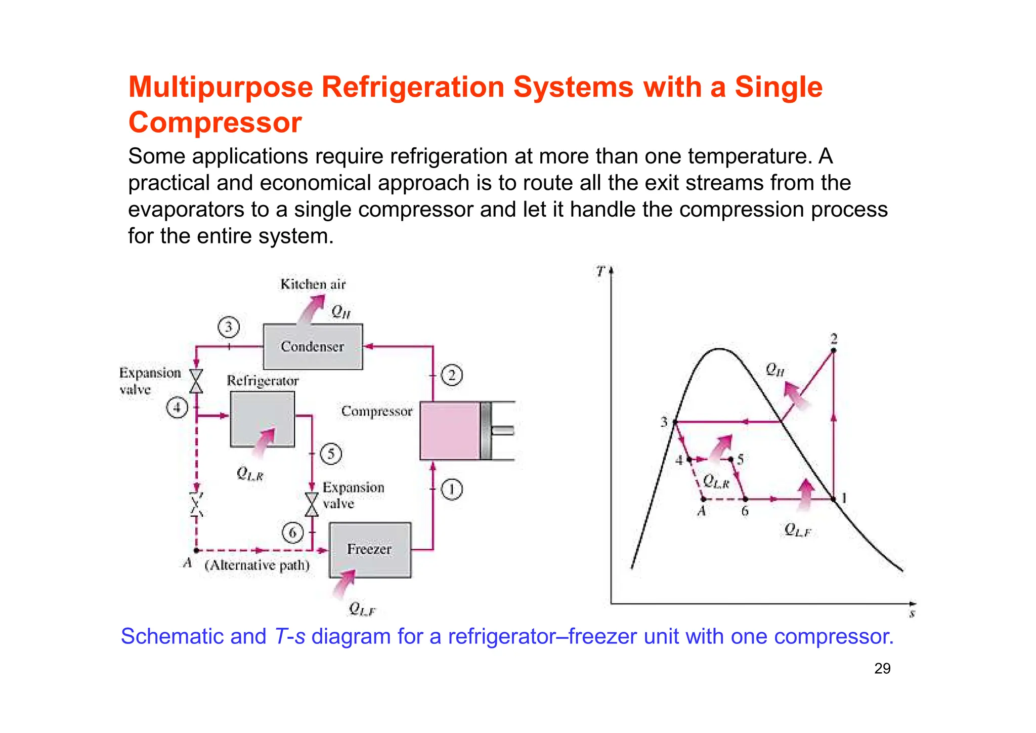
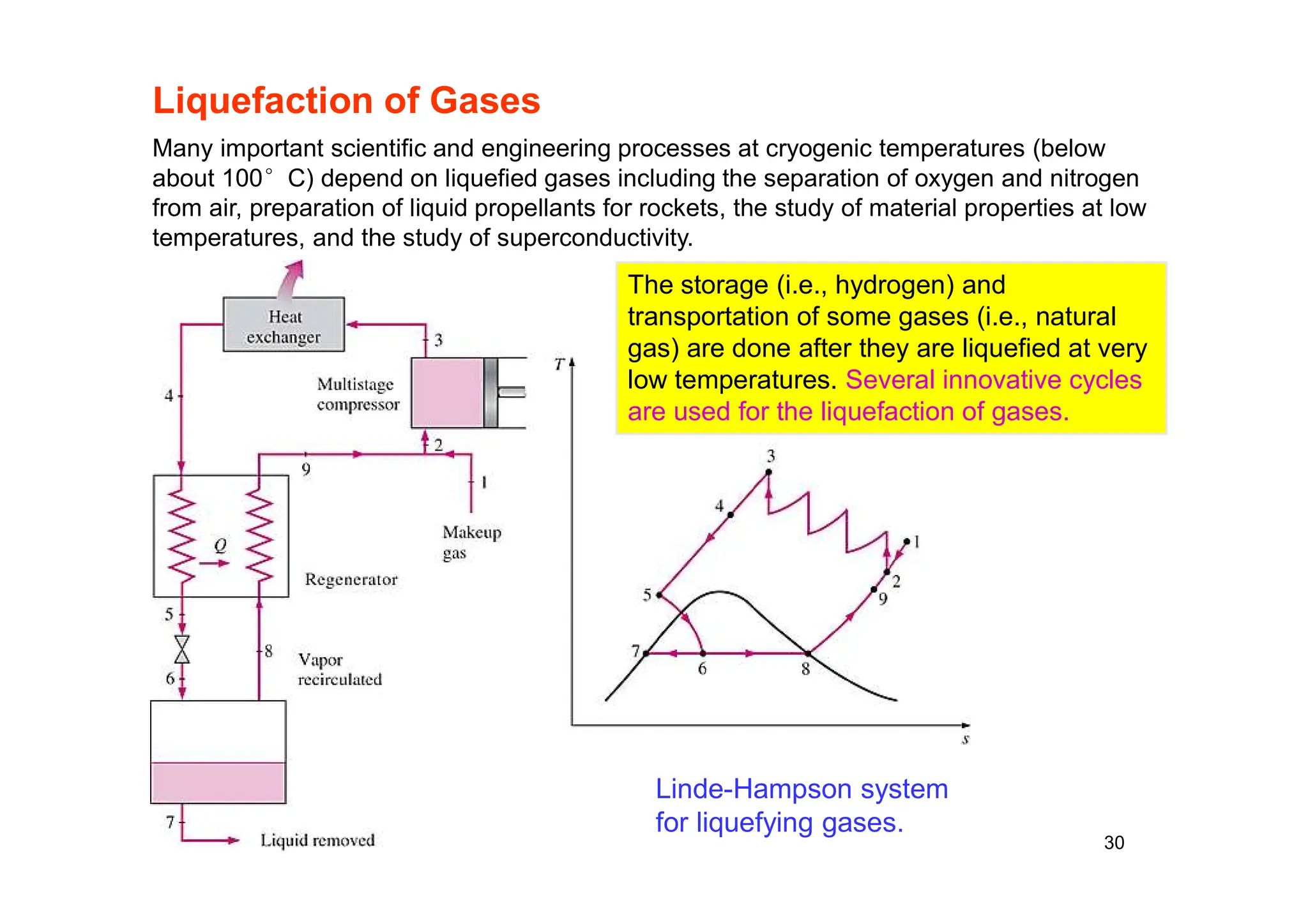
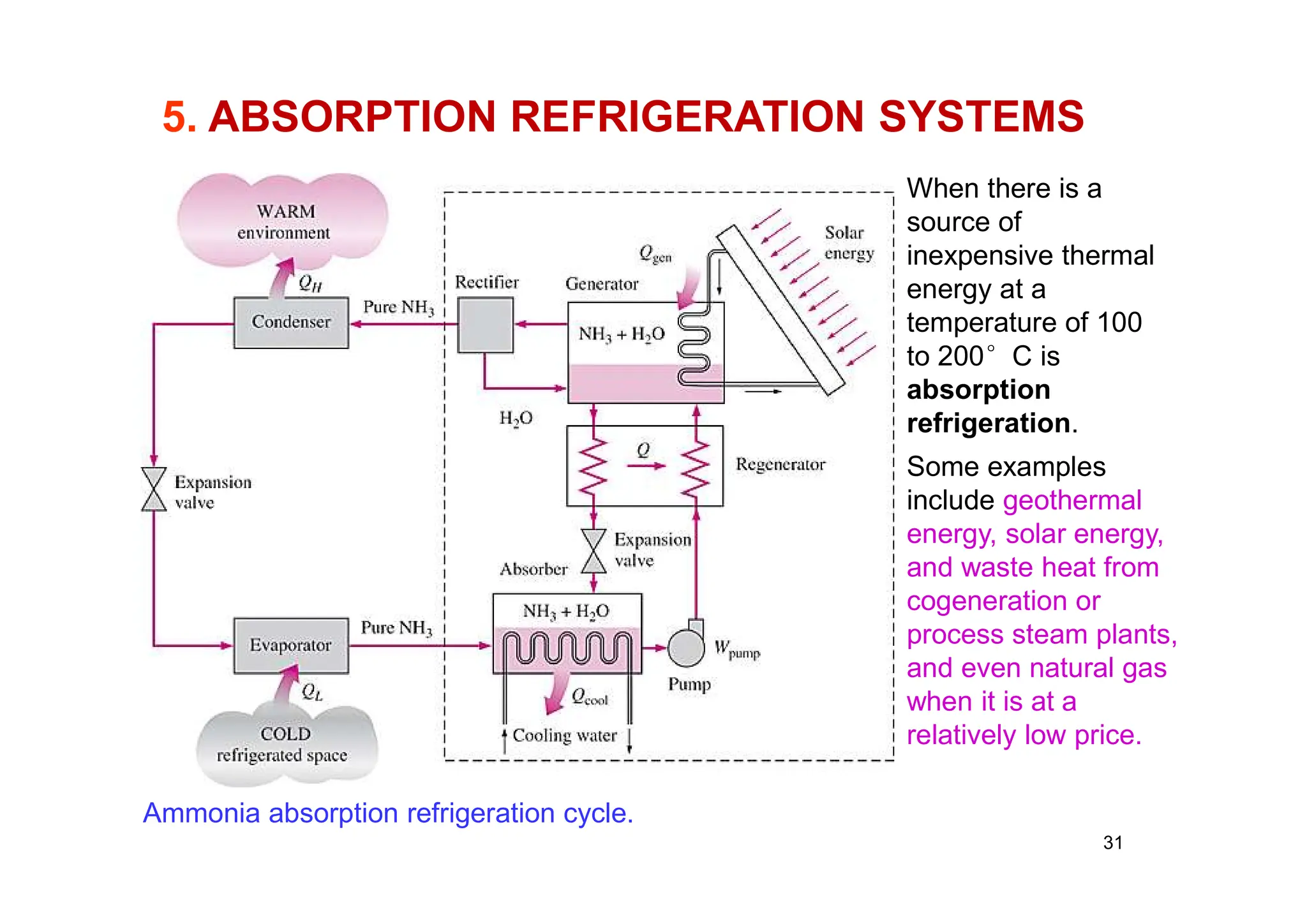
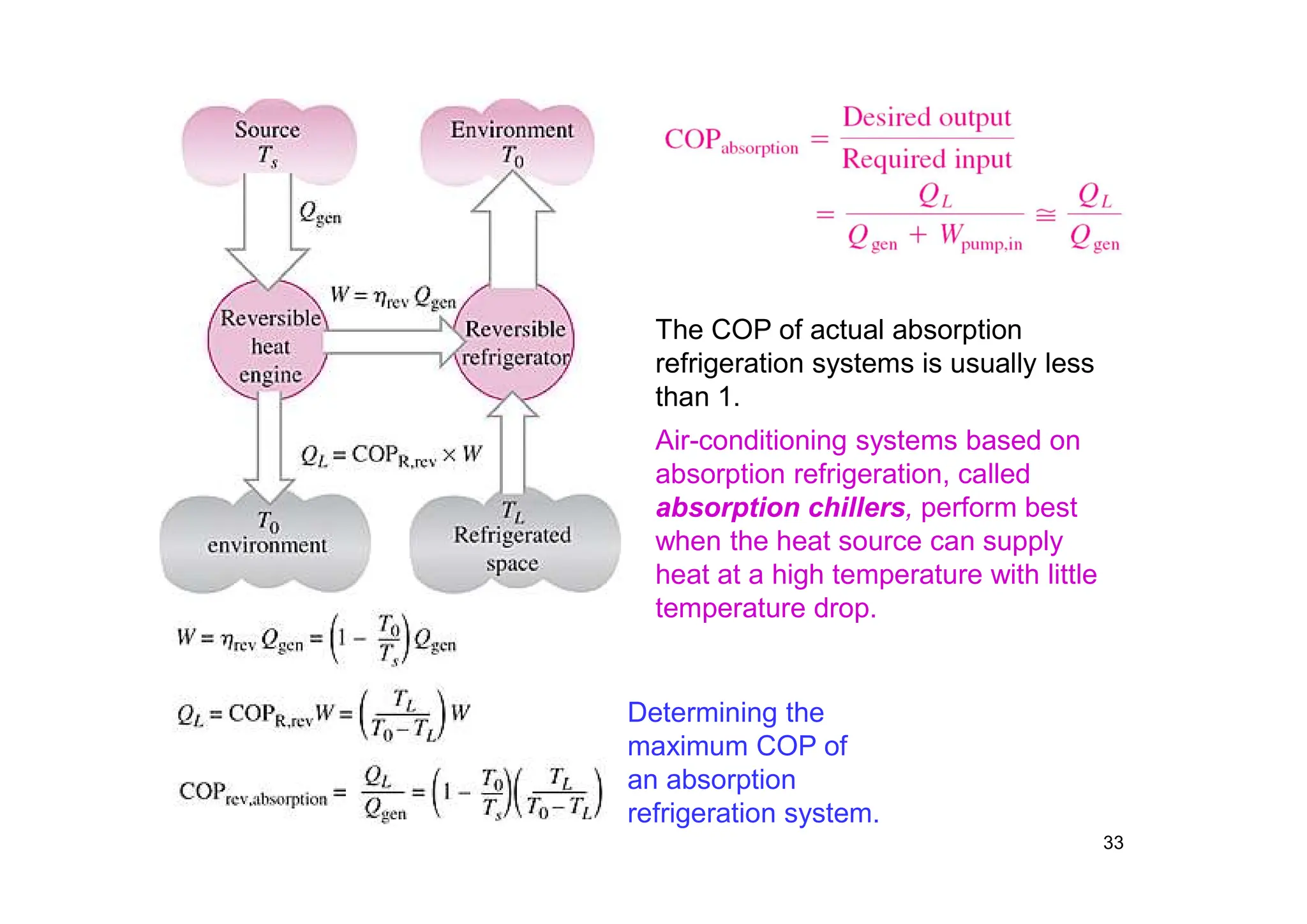
CHAPTER 1
REFRIGERATION CYCLES
.
2
1. OBJECTIVE
• Introduce the concepts of refrigerators and heat pumps
and the measure of their performance.
• Analyze the ideal vapor-compression refrigeration cycle.
• Analyze the actual vapor-compression refrigeration cycle.
• Review the factors involved in selecting the right
refrigerant for an application.
• Discuss the operation of refrigeration and heat pump
systems.
• Evaluate the performance of innovative vapor-
compression refrigeration systems.
• Analyze gas refrigeration systems.
• Introduce the concepts of absorption-refrigeration
systems.
PRINCIPLES OF REFRIGERATION
Refrigeration means to cool an object below its
surrounding temperature
3
1. VAPOUR COMPRESSION CYCLE
Basic components of the vapour
compression refrigeration system
4
CONDENSER
EVAPORATOR
COMPRESSOR
EXPANSION VALVE
2
1
3
4
• Compressor
• Condenser
• Throttling Device
• Evaporator
Vapour Compression Cycle
PRESSURE
5
COMPRESSION
CONDENSATION
EVAPORATION
`THROTTLING
REFRIGERATION EFFECT WORK DONE
CONDENSER HEAT REJECTION
ENTHALPY
KN/m2
KJ/Kg
Pd
Pe
1
2
3
4
CONDENSER
EVAPORATOR
COMPRESSOR
EXPANSION VALVE
2
1
3
4
6
REVIEW ON
REFIGERATION
The objective of a refrigerator is to remove heat
(QL) from the cold medium; the objective of a heat
pump is to supply heat (QH) to a warm medium.
The transfer of heat from a low-temperature
region to a high-temperature one requires
special devices called refrigerators.
Refrigerators and heat pumps are essentially
the same devices; they differ in their
objectives only.
for fixed values of QL and QH
Unit of Refrigeration
The unit of refrigeration is kW or TR
TON OF REFRIGERATION ( TR )
1 TR = 12’000 Btu/hr BRITISH UNITS
1 TR = 3.517 KW SI UNITS
7
8
THE IDEAL VAPOR-COMPRESSION REFRIGERATION CYCLE
The vapor-compression refrigeration cycle is the ideal model for refrigeration
systems. Unlike the reversed Carnot cycle, the refrigerant is vaporized completely
before it is compressed and the turbine is replaced with a throttling device.
Schematic and T-s diagram for the ideal
vapor-compression refrigeration cycle.
This is the
most widely
used cycle for
refrigerators,
A-C systems,
and heat
pumps.
9
1
4
1
’
4
’
Heating output
Cooling output
Energ
y
input
2
4 3
2
’
4
’
1
’
3
’
4
’
1
’
3
’
2
’
h4=h3 h1 h2
COP =
Total energy input
Coolingg output (h2-h4)
(h2-h1)
Total energy input
O`
(h1-h4)
(h2-h1)
The Refrigeration Cycle on p-h Chart
11
12
An ordinary
household
refrigerator.
The P-h diagram of an ideal vapor-
compression refrigeration cycle.
The ideal vapor-compression refrigeration cycle involves an irreversible (throttling)
process to make it a more realistic model for the actual systems.
Replacing the expansion valve by a turbine is not practical since the added
benefits cannot justify the added cost and complexity.
Steady-flow
energy balance
Refrigeration Cycle Efficiency
The refrigeration cycle efficiency is known as
COEFFICIENT OF PERFORMANCE (COPREF)
(COPREF) = Refrigeration Effect KJ/Kg
Work Done KJ/Kg
(COPHP) = Condenser Heat Rejection KJ/Kg
Work Done KJ/Kg
13
14
15
16
Actual Vapor-compression Refrigeration Cycle
An actual vapor-compression refrigeration cycle differs from the ideal one in
several ways, owing mostly to the irreversibilities that occur in various
components, mainly due to fluid friction (causes pressure drops) and heat transfer
to or from the surroundings. The COP decreases as a result of irreversibilities.
17
18
19
20
21
22
3. REFRIGERANTS
23
24
25
4. HEAT PUMP SYSTEMS
A heat pump can be
used to heat a house
in winter and to cool
it in summer.
The most common energy source for
heat pumps is atmospheric air (air-to-
air systems).
Water-source systems usually use
well water and ground-source
(geothermal) heat pumps use earth as
the energy source. They typically have
higher COPs but are more complex
and more expensive to install.
Both the capacity and the efficiency of
a heat pump fall significantly at low
temperatures. Therefore, most air-
source heat pumps require a
supplementary heating system such
as electric resistance heaters or a gas
furnace.
Heat pumps are most competitive in
areas that have a large cooling load
during the cooling season and a
relatively small heating load during the
heating season. In these areas, the
heat pump can meet the entire cooling
and heating needs of residential or
commercial buildings.
26
5. INNOVATIVE VAPOR-COMPRESSION
REFRIGERATION SYSTEMS
• The simple vapor-compression refrigeration cycle is the most widely
used refrigeration cycle, and it is adequate for most refrigeration
applications.
• The ordinary vapor-compression refrigeration systems are simple,
inexpensive, reliable, and practically maintenance-free.
• However, for large industrial applications efficiency, not simplicity, is
the major concern.
• Also, for some applications the simple vapor-compression
refrigeration cycle is inadequate and needs to be modified.
• For moderately and very low temperature applications some
innovative refrigeration systems are used. The following cycles will be
discussed:
• Cascade refrigeration systems
• Multistage compression refrigeration systems
• Multipurpose refrigeration systems with a single compressor
• Liquefaction of gases
27
Cascade Refrigeration Systems
A two-stage cascade refrigeration system
with the same refrigerant in both stages.
Some industrial applications require moderately low temperatures, and the
temperature range they involve may be too large for a single vapor-compression
refrigeration cycle to be practical. The solution is cascading.
Cascading
improves the
COP of a
refrigeration
system.
Some systems
use three or
four stages of
cascading.
28
Multistage
Compression
Refrigeration Systems
A two-stage compression refrigeration
system with a flash chamber.
When the fluid used throughout the cascade
refrigeration system is the same, the heat
exchanger between the stages can be replaced
by a mixing chamber (called a flash chamber)
since it has better heat transfer characteristics.
29
Multipurpose Refrigeration Systems with a Single
Compressor
Schematic and T-s diagram for a refrigerator–freezer unit with one compressor.
Some applications require refrigeration at more than one temperature. A
practical and economical approach is to route all the exit streams from the
evaporators to a single compressor and let it handle the compression process
for the entire system.
30
Liquefaction of Gases
Linde-Hampson system
for liquefying gases.
Many important scientific and engineering processes at cryogenic temperatures (below
about 100°C) depend on liquefied gases including the separation of oxygen and nitrogen
from air, preparation of liquid propellants for rockets, the study of material properties at low
temperatures, and the study of superconductivity.
The storage (i.e., hydrogen) and
transportation of some gases (i.e., natural
gas) are done after they are liquefied at very
low temperatures. Several innovative cycles
are used for the liquefaction of gases.
31
5. ABSORPTION REFRIGERATION SYSTEMS
Ammonia absorption refrigeration cycle.
When there is a
source of
inexpensive thermal
energy at a
temperature of 100
to 200°C is
absorption
refrigeration.
Some examples
include geothermal
energy, solar energy,
and waste heat from
cogeneration or
process steam plants,
and even natural gas
when it is at a
relatively low price.
32
• Absorption refrigeration systems (ARS) involve the absorption of a
refrigerant by a transport medium.
• The most widely used system is the ammonia–water system, where
ammonia (NH3) serves as the refrigerant and water (H2O) as the transport
medium.
• Other systems include water–lithium bromide and water–lithium chloride
systems, where water serves as the refrigerant. These systems are limited
to applications such as A-C where the minimum temperature is above the
freezing point of water.
• Compared with vapor-compression systems, ARS have one major
advantage: A liquid is compressed instead of a vapor and as a result the
work input is very small (on the order of one percent of the heat supplied to
the generator) and often neglected in the cycle analysis.
• ARS are often classified as heat-driven systems.
• ARS are much more expensive than the vapor-compression refrigeration
systems. They are more complex and occupy more space, they are much
less efficient thus requiring much larger cooling towers to reject the waste
heat, and they are more difficult to service since they are less common.
• Therefore, ARS should be considered only when the unit cost of thermal
energy is low and is projected to remain low relative to electricity.
• ARS are primarily used in large commercial and industrial installations.
33
Determining the
maximum COP of
an absorption
refrigeration system.
The COP of actual absorption
refrigeration systems is usually less
than 1.
Air-conditioning systems based on
absorption refrigeration, called
absorption chillers, perform best
when the heat source can supply
heat at a high temperature with little
temperature drop.
REVIEW QUESTIONS
• 1. Describe Ideal Vapor-Compression Refrigeration Cycle I T-S
and P-H digram and define the process
• 2. Draw Actual Vapor-Compression Refrigeration Cycle in P-H
diagram
• 3. Describe with aid of sketch vapor absorption refrigeration
cycle.
• 4. How do you select the right Refrigerant.
• 5. What is the difference between rRefrigeration and heat
pump?
• 6. Define COP for refrigerator and heat pump
• 7. What is cascaded refrigeration cycles and what are the
advantages.
34
ASSIGNMENT
1. Design refrigeration cycles for a cold room in Afdera and
Semen Mountain parks Using R132 as refrigerant to be
maintained -20 oC and determine the COP for both cases.
The maximum temperature for 97.5 % probability in Afdera
is 45OC and Ras Dashen 20oC. Assume that the condenser
temperature can be 5 oC above the ambient temperature
and the evaporator temperature shall be 5oC below the
freeze temperature.
35

Chapter 1 refrigeration cycles and air conditioning

  • 1.
  • 2.
    2 1. OBJECTIVE • Introducethe concepts of refrigerators and heat pumps and the measure of their performance. • Analyze the ideal vapor-compression refrigeration cycle. • Analyze the actual vapor-compression refrigeration cycle. • Review the factors involved in selecting the right refrigerant for an application. • Discuss the operation of refrigeration and heat pump systems. • Evaluate the performance of innovative vapor- compression refrigeration systems. • Analyze gas refrigeration systems. • Introduce the concepts of absorption-refrigeration systems.
  • 3.
    PRINCIPLES OF REFRIGERATION Refrigerationmeans to cool an object below its surrounding temperature 3
  • 4.
    1. VAPOUR COMPRESSIONCYCLE Basic components of the vapour compression refrigeration system 4 CONDENSER EVAPORATOR COMPRESSOR EXPANSION VALVE 2 1 3 4 • Compressor • Condenser • Throttling Device • Evaporator
  • 5.
    Vapour Compression Cycle PRESSURE 5 COMPRESSION CONDENSATION EVAPORATION `THROTTLING REFRIGERATIONEFFECT WORK DONE CONDENSER HEAT REJECTION ENTHALPY KN/m2 KJ/Kg Pd Pe 1 2 3 4 CONDENSER EVAPORATOR COMPRESSOR EXPANSION VALVE 2 1 3 4
  • 6.
    6 REVIEW ON REFIGERATION The objectiveof a refrigerator is to remove heat (QL) from the cold medium; the objective of a heat pump is to supply heat (QH) to a warm medium. The transfer of heat from a low-temperature region to a high-temperature one requires special devices called refrigerators. Refrigerators and heat pumps are essentially the same devices; they differ in their objectives only. for fixed values of QL and QH
  • 7.
    Unit of Refrigeration Theunit of refrigeration is kW or TR TON OF REFRIGERATION ( TR ) 1 TR = 12’000 Btu/hr BRITISH UNITS 1 TR = 3.517 KW SI UNITS 7
  • 8.
    8 THE IDEAL VAPOR-COMPRESSIONREFRIGERATION CYCLE The vapor-compression refrigeration cycle is the ideal model for refrigeration systems. Unlike the reversed Carnot cycle, the refrigerant is vaporized completely before it is compressed and the turbine is replaced with a throttling device. Schematic and T-s diagram for the ideal vapor-compression refrigeration cycle. This is the most widely used cycle for refrigerators, A-C systems, and heat pumps.
  • 9.
  • 10.
    1 4 1 ’ 4 ’ Heating output Cooling output Energ y input 2 43 2 ’ 4 ’ 1 ’ 3 ’ 4 ’ 1 ’ 3 ’ 2 ’ h4=h3 h1 h2 COP = Total energy input Coolingg output (h2-h4) (h2-h1) Total energy input O` (h1-h4) (h2-h1) The Refrigeration Cycle on p-h Chart
  • 11.
  • 12.
    12 An ordinary household refrigerator. The P-hdiagram of an ideal vapor- compression refrigeration cycle. The ideal vapor-compression refrigeration cycle involves an irreversible (throttling) process to make it a more realistic model for the actual systems. Replacing the expansion valve by a turbine is not practical since the added benefits cannot justify the added cost and complexity. Steady-flow energy balance
  • 13.
    Refrigeration Cycle Efficiency Therefrigeration cycle efficiency is known as COEFFICIENT OF PERFORMANCE (COPREF) (COPREF) = Refrigeration Effect KJ/Kg Work Done KJ/Kg (COPHP) = Condenser Heat Rejection KJ/Kg Work Done KJ/Kg 13
  • 14.
  • 15.
  • 16.
    16 Actual Vapor-compression RefrigerationCycle An actual vapor-compression refrigeration cycle differs from the ideal one in several ways, owing mostly to the irreversibilities that occur in various components, mainly due to fluid friction (causes pressure drops) and heat transfer to or from the surroundings. The COP decreases as a result of irreversibilities.
  • 17.
  • 18.
  • 19.
  • 20.
  • 21.
  • 22.
  • 23.
  • 24.
  • 25.
    25 4. HEAT PUMPSYSTEMS A heat pump can be used to heat a house in winter and to cool it in summer. The most common energy source for heat pumps is atmospheric air (air-to- air systems). Water-source systems usually use well water and ground-source (geothermal) heat pumps use earth as the energy source. They typically have higher COPs but are more complex and more expensive to install. Both the capacity and the efficiency of a heat pump fall significantly at low temperatures. Therefore, most air- source heat pumps require a supplementary heating system such as electric resistance heaters or a gas furnace. Heat pumps are most competitive in areas that have a large cooling load during the cooling season and a relatively small heating load during the heating season. In these areas, the heat pump can meet the entire cooling and heating needs of residential or commercial buildings.
  • 26.
    26 5. INNOVATIVE VAPOR-COMPRESSION REFRIGERATIONSYSTEMS • The simple vapor-compression refrigeration cycle is the most widely used refrigeration cycle, and it is adequate for most refrigeration applications. • The ordinary vapor-compression refrigeration systems are simple, inexpensive, reliable, and practically maintenance-free. • However, for large industrial applications efficiency, not simplicity, is the major concern. • Also, for some applications the simple vapor-compression refrigeration cycle is inadequate and needs to be modified. • For moderately and very low temperature applications some innovative refrigeration systems are used. The following cycles will be discussed: • Cascade refrigeration systems • Multistage compression refrigeration systems • Multipurpose refrigeration systems with a single compressor • Liquefaction of gases
  • 27.
    27 Cascade Refrigeration Systems Atwo-stage cascade refrigeration system with the same refrigerant in both stages. Some industrial applications require moderately low temperatures, and the temperature range they involve may be too large for a single vapor-compression refrigeration cycle to be practical. The solution is cascading. Cascading improves the COP of a refrigeration system. Some systems use three or four stages of cascading.
  • 28.
    28 Multistage Compression Refrigeration Systems A two-stagecompression refrigeration system with a flash chamber. When the fluid used throughout the cascade refrigeration system is the same, the heat exchanger between the stages can be replaced by a mixing chamber (called a flash chamber) since it has better heat transfer characteristics.
  • 29.
    29 Multipurpose Refrigeration Systemswith a Single Compressor Schematic and T-s diagram for a refrigerator–freezer unit with one compressor. Some applications require refrigeration at more than one temperature. A practical and economical approach is to route all the exit streams from the evaporators to a single compressor and let it handle the compression process for the entire system.
  • 30.
    30 Liquefaction of Gases Linde-Hampsonsystem for liquefying gases. Many important scientific and engineering processes at cryogenic temperatures (below about 100°C) depend on liquefied gases including the separation of oxygen and nitrogen from air, preparation of liquid propellants for rockets, the study of material properties at low temperatures, and the study of superconductivity. The storage (i.e., hydrogen) and transportation of some gases (i.e., natural gas) are done after they are liquefied at very low temperatures. Several innovative cycles are used for the liquefaction of gases.
  • 31.
    31 5. ABSORPTION REFRIGERATIONSYSTEMS Ammonia absorption refrigeration cycle. When there is a source of inexpensive thermal energy at a temperature of 100 to 200°C is absorption refrigeration. Some examples include geothermal energy, solar energy, and waste heat from cogeneration or process steam plants, and even natural gas when it is at a relatively low price.
  • 32.
    32 • Absorption refrigerationsystems (ARS) involve the absorption of a refrigerant by a transport medium. • The most widely used system is the ammonia–water system, where ammonia (NH3) serves as the refrigerant and water (H2O) as the transport medium. • Other systems include water–lithium bromide and water–lithium chloride systems, where water serves as the refrigerant. These systems are limited to applications such as A-C where the minimum temperature is above the freezing point of water. • Compared with vapor-compression systems, ARS have one major advantage: A liquid is compressed instead of a vapor and as a result the work input is very small (on the order of one percent of the heat supplied to the generator) and often neglected in the cycle analysis. • ARS are often classified as heat-driven systems. • ARS are much more expensive than the vapor-compression refrigeration systems. They are more complex and occupy more space, they are much less efficient thus requiring much larger cooling towers to reject the waste heat, and they are more difficult to service since they are less common. • Therefore, ARS should be considered only when the unit cost of thermal energy is low and is projected to remain low relative to electricity. • ARS are primarily used in large commercial and industrial installations.
  • 33.
    33 Determining the maximum COPof an absorption refrigeration system. The COP of actual absorption refrigeration systems is usually less than 1. Air-conditioning systems based on absorption refrigeration, called absorption chillers, perform best when the heat source can supply heat at a high temperature with little temperature drop.
  • 34.
    REVIEW QUESTIONS • 1.Describe Ideal Vapor-Compression Refrigeration Cycle I T-S and P-H digram and define the process • 2. Draw Actual Vapor-Compression Refrigeration Cycle in P-H diagram • 3. Describe with aid of sketch vapor absorption refrigeration cycle. • 4. How do you select the right Refrigerant. • 5. What is the difference between rRefrigeration and heat pump? • 6. Define COP for refrigerator and heat pump • 7. What is cascaded refrigeration cycles and what are the advantages. 34
  • 35.
    ASSIGNMENT 1. Design refrigerationcycles for a cold room in Afdera and Semen Mountain parks Using R132 as refrigerant to be maintained -20 oC and determine the COP for both cases. The maximum temperature for 97.5 % probability in Afdera is 45OC and Ras Dashen 20oC. Assume that the condenser temperature can be 5 oC above the ambient temperature and the evaporator temperature shall be 5oC below the freeze temperature. 35