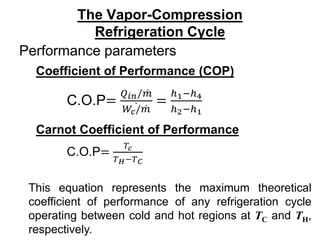
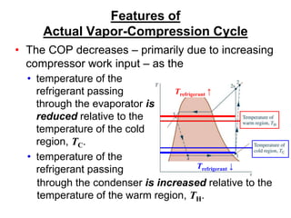
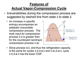
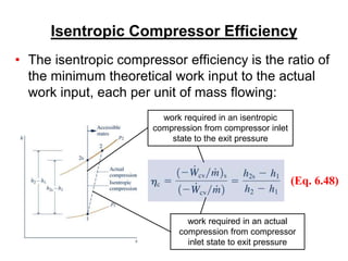
Vapor Compression
Refrigeration Cycle
• There are four principal
control volumes involving
these components:
• Evaporator
• Compressor
• Condenser
• Expansion valve
• Most common refrigeration cycle in use today
All energy transfers by work and heat are taken as positive in
the directions of the arrows on the schematic and energy
balances are written accordingly.
Two-phase
liquid-vapor mixture
The Vapor-Compression
Refrigeration Cycle
Process 4-1: two-phase liquid-vapor
mixture of refrigerant is evaporated
through heat transfer from the
refrigerated space.
Process 1-2: vapor refrigerant is
compressed to a relatively high
temperature and pressure requiring
work input.
Process 2-3: vapor refrigerant
condenses to liquid through heat
transfer to the cooler surroundings.
Process 3-4: liquid refrigerant
expands to the evaporator pressure.
•The processes of this cycle are
Two-phase
liquid-vapor mixture
Coefficient of Performance (COP)
The Vapor-Compression
Refrigeration Cycle
Performance parameters
Carnot Coefficient of Performance
This equation represents the maximum theoretical
coefficient of performance of any refrigeration cycle
operating between cold and hot regions at TC and TH,
respectively.
Features of
Actual Vapor-Compression Cycle
• Heat transfers between refrigerant and cold and
warm regions are not reversible.
• Refrigerant temperature
in evaporator is less than
TC.
• Refrigerant temperature
in condenser is greater
than TH.
• Irreversible heat
transfers have negative
effect on performance.
Features of
Actual Vapor-Compression Cycle
• The COP decreases – primarily due to increasing
compressor work input – as the
• temperature of the
refrigerant passing
through the evaporator is
reduced relative to the
temperature of the cold
region, TC.
• temperature of the
refrigerant passing
through the condenser is increased relative to the
temperature of the warm region, TH.
Trefrigerant ↓
Trefrigerant ↑
Features of
Actual Vapor-Compression Cycle
• Irreversibilities during the compression process are
suggested by dashed line from state 1 to state 2.
• An increase in specific
entropy accompanies an
adiabatic irreversible
compression process. The
work input for compression
process 1-2 is greater than
for the counterpart isentropic
compression process 1-2s.
• Since process 4-1, and thus the refrigeration capacity,
is the same for cycles 1-2-3-4-1 and 1-2s-3-4-1, cycle
1-2-3-4-1 has the lower COP.
Isentropic Compressor Efficiency
• The isentropic compressor efficiency is the ratio of
the minimum theoretical work input to the actual
work input, each per unit of mass flowing:
(Eq. 6.48)
work required in an actual
compression from compressor
inlet state to exit pressure
work required in an isentropic
compression from compressor inlet
state to the exit pressure
p-h Diagram
►The pressure-enthalpy (p-h) diagram is a
thermodynamic property diagram commonly used
in the refrigeration field.
9
Other Refrigeration Cycles
Cascade refrigeration systems
Very low temperatures can be achieved by operating two or more vapor-compression
systems in series, called cascading. The COP of a refrigeration system also
increases as a result of cascading.
10
Multistage compression refrigeration systems
11
Multipurpose refrigeration systems
A refrigerator with a single compressor can provide refrigeration at several
temperatures by throttling the refrigerant in stages.
12
Liquefaction of gases
Another way of improving the performance of a vapor-compression refrigeration
system is by using multistage compression with regenerative cooling. The vapor-
compression refrigeration cycle can also be used to liquefy gases after some
modifications.
Selecting Refrigerants
►Refrigerant selection is based on several
factors:
►Performance: provides adequate cooling
capacity cost-effectively.
►Safety: avoids hazards (i.e., toxicity).
►Environmental impact: minimizes harm to
stratospheric ozone layer and reduces
negative impact to global climate change.
Refrigerant Types and Characteristics
Global Warming Potential (GWP) is a simplified index that estimates the potential
future influence on global warming associated with different gases when released
to the atmosphere.
Refrigerant Types and Characteristics
•Chlorofluorocarbons (CFCs) and Hydrochlorofluorocarbons
(HCFCs) are early synthetic refrigerants each containing chlorine.
Because of the adverse effect of chlorine on Earth’s stratospheric
ozone layer, use of these refrigerants is regulated by international
agreement.
•Hydrofluorocarbons (HFCs) and HFC blends are chlorine-free
refrigerants. Blends combine two or more HFCs. While these
chlorine-free refrigerants do not contribute to ozone depletion, with
the exception of R-1234yf, they have high GWP levels.
•Natural refrigerants are nonsynthetic, naturally occurring
substances which serve as refrigerants. These include carbon
dioxide, ammonia, and hydrocarbons. These refrigerants feature
low GWP values; still, concerns have been raised over the toxicity
of NH3 and the safety of the hydrocarbons.

RAC-Akash-Langde..ppt

  • 1.
    Vapor Compression Refrigeration Cycle •There are four principal control volumes involving these components: • Evaporator • Compressor • Condenser • Expansion valve • Most common refrigeration cycle in use today All energy transfers by work and heat are taken as positive in the directions of the arrows on the schematic and energy balances are written accordingly. Two-phase liquid-vapor mixture
  • 2.
    The Vapor-Compression Refrigeration Cycle Process4-1: two-phase liquid-vapor mixture of refrigerant is evaporated through heat transfer from the refrigerated space. Process 1-2: vapor refrigerant is compressed to a relatively high temperature and pressure requiring work input. Process 2-3: vapor refrigerant condenses to liquid through heat transfer to the cooler surroundings. Process 3-4: liquid refrigerant expands to the evaporator pressure. •The processes of this cycle are Two-phase liquid-vapor mixture
  • 3.
    Coefficient of Performance(COP) The Vapor-Compression Refrigeration Cycle Performance parameters Carnot Coefficient of Performance This equation represents the maximum theoretical coefficient of performance of any refrigeration cycle operating between cold and hot regions at TC and TH, respectively.
  • 4.
    Features of Actual Vapor-CompressionCycle • Heat transfers between refrigerant and cold and warm regions are not reversible. • Refrigerant temperature in evaporator is less than TC. • Refrigerant temperature in condenser is greater than TH. • Irreversible heat transfers have negative effect on performance.
  • 5.
    Features of Actual Vapor-CompressionCycle • The COP decreases – primarily due to increasing compressor work input – as the • temperature of the refrigerant passing through the evaporator is reduced relative to the temperature of the cold region, TC. • temperature of the refrigerant passing through the condenser is increased relative to the temperature of the warm region, TH. Trefrigerant ↓ Trefrigerant ↑
  • 6.
    Features of Actual Vapor-CompressionCycle • Irreversibilities during the compression process are suggested by dashed line from state 1 to state 2. • An increase in specific entropy accompanies an adiabatic irreversible compression process. The work input for compression process 1-2 is greater than for the counterpart isentropic compression process 1-2s. • Since process 4-1, and thus the refrigeration capacity, is the same for cycles 1-2-3-4-1 and 1-2s-3-4-1, cycle 1-2-3-4-1 has the lower COP.
  • 7.
    Isentropic Compressor Efficiency •The isentropic compressor efficiency is the ratio of the minimum theoretical work input to the actual work input, each per unit of mass flowing: (Eq. 6.48) work required in an actual compression from compressor inlet state to exit pressure work required in an isentropic compression from compressor inlet state to the exit pressure
  • 8.
    p-h Diagram ►The pressure-enthalpy(p-h) diagram is a thermodynamic property diagram commonly used in the refrigeration field.
  • 9.
    9 Other Refrigeration Cycles Cascaderefrigeration systems Very low temperatures can be achieved by operating two or more vapor-compression systems in series, called cascading. The COP of a refrigeration system also increases as a result of cascading.
  • 10.
  • 11.
    11 Multipurpose refrigeration systems Arefrigerator with a single compressor can provide refrigeration at several temperatures by throttling the refrigerant in stages.
  • 12.
    12 Liquefaction of gases Anotherway of improving the performance of a vapor-compression refrigeration system is by using multistage compression with regenerative cooling. The vapor- compression refrigeration cycle can also be used to liquefy gases after some modifications.
  • 13.
    Selecting Refrigerants ►Refrigerant selectionis based on several factors: ►Performance: provides adequate cooling capacity cost-effectively. ►Safety: avoids hazards (i.e., toxicity). ►Environmental impact: minimizes harm to stratospheric ozone layer and reduces negative impact to global climate change.
  • 14.
    Refrigerant Types andCharacteristics Global Warming Potential (GWP) is a simplified index that estimates the potential future influence on global warming associated with different gases when released to the atmosphere.
  • 15.
    Refrigerant Types andCharacteristics •Chlorofluorocarbons (CFCs) and Hydrochlorofluorocarbons (HCFCs) are early synthetic refrigerants each containing chlorine. Because of the adverse effect of chlorine on Earth’s stratospheric ozone layer, use of these refrigerants is regulated by international agreement. •Hydrofluorocarbons (HFCs) and HFC blends are chlorine-free refrigerants. Blends combine two or more HFCs. While these chlorine-free refrigerants do not contribute to ozone depletion, with the exception of R-1234yf, they have high GWP levels. •Natural refrigerants are nonsynthetic, naturally occurring substances which serve as refrigerants. These include carbon dioxide, ammonia, and hydrocarbons. These refrigerants feature low GWP values; still, concerns have been raised over the toxicity of NH3 and the safety of the hydrocarbons.

Editor's Notes