ADITYA ENGINEERING COLLEGE(A)
ADITYA ENGINEERING COLLEGE (A)
SIMPLE VAPOUR COMPRESSION
REFRIGERATION SYSTEM
UNIT-II
Dr. P.K. DAS
Professor, Dept. of Mechanical Engineering
Aditya Engineering College (A)
2.
Aditya Engineering College(A)
R&AC Dr. Pritam Kumar Das 2
Vapour Compression Refrigeration
Working principle and essential components of the plant – simple vapour
compression refrigeration cycle – COP –
Representation of cycle on T-S and p-h charts
Effect of sub cooling and super heating – cycle analysis
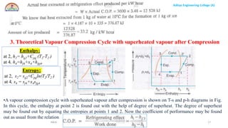
Actual cycle influence of various parameters on system performance – use of
p-h charts – numerical problems.
Vapour Compression refrigeration System Components
3.
Aditya Engineering College(A)
R&AC Dr. Pritam Kumar Das
Aditya Engineering College (A)
3
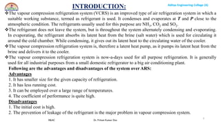
The vapour compression refrigeration system (VCRS) is an improved type of air refrigeration system in which a
suitable working substance, termed as refrigerant is used. It condenses and evaporates at T and P close to the
atmospheric condition. The refrigerants usually used for this purpose are NH3, CO2 and SO2.
The refrigerant does not leave the system, but is throughout the system alternately condensing and evaporating.
In evaporating, the refrigerant absorbs its latent heat from the brine (salt water) which is used for circulating it
around the cold chamber. While condensing, it gives out its latent heat to the circulating water of the cooler.
The vapour compression refrigeration system is, therefore a latent heat pump, as it pumps its latent heat from the
brine and delivers it to the cooler.
The vapour compression refrigeration system is now-a-days used for all purpose refrigeration. It is generally
used for all industrial purposes from a small domestic refrigerator to a big air conditioning plant.
INTRODUCTION:
Following are the advantages and disadvantages of the system over ARS:
Advantages
1. It has smaller size for the given capacity of refrigeration.
2. It has less running cost.
3. It can be employed over a large range of temperatures.
4. The coefficient of performance is quite high.
Disadvantages
1. The initial cost is high.
2. The prevention of leakage of the refrigerant is the major problem in vapour compression system.
4.
Aditya Engineering College(A)
R&AC Dr. Pritam Kumar Das
Aditya Engineering College (A)
4
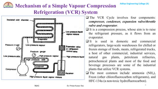
The VCR Cycle involves four components:
compressor, condenser, expansion valve/throttle
valve and evaporator.
It is a compression process, whose aim is to raise
the refrigerant pressure, as it flows from an
evaporator.
It is used in domestic and commercial
refrigerators, large-scale warehouses for chilled or
frozen storage of foods, meats, refrigerated trucks,
a host of other commercial, industrial services,
natural gas plants, petroleum refineries,
petrochemical plants and most of the food and
beverage processes are some of the industrial
plants that utilize VCR systems.
The most common include ammonia (NH3),
Freon (other chlorofluorocarbon refrigerants), and
HFC-134a (a non-toxic hydrofluorocarbon).
Mechanism of a Simple Vapour Compression
Refrigeration (VCR) System
5.
Aditya Engineering College(A)
R&AC Dr. Pritam Kumar Das
Aditya Engineering College (A)
5
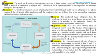
Receiver: The condensed liquid refrigerant from the
condenser is stored in a vessel known as receiver from
where it is supplied to the evaporator through the
expansion valve or refrigerant control valve.
Expansion valve: It is also called throttle valve or
refrigerant control valve. The function of the expansion
valve is to allow the liquid refrigerant under high P and T
to pass at a controlled rate after reducing its P and T. Some
of the liquid refrigerant evaporates as it passes through the
expansion valve, but the greater portion is vaporised in the
evaporator at the low P and T.
Evaporator: An evaporator consists of coils of pipe in
which the liquid-vapour refrigerant at low P and T is
evaporated and changed into vapour refrigerant at low P
and T. In evaporating, the liquid vapour refrigerant absorbs
its latent heat of vaporisation from the medium (air, water
or brine) which is to be cooled.
Compressor: The low P and T vapour refrigerant from evaporator is drawn into the compressor through the inlet or suction
valve A, where it is compressed to a high P and T. This high P and T vapour refrigerant is discharged into the condenser
through the delivery valve B.
Condenser: The condenser or cooler consists of coils of pipe in which the high P and T vapour refrigerant is cooled and
condensed. the refrigerant, while, passing through the condenser, gives up its latent heat to the surrounding condensing
medium which is normally air or water.
6.
Aditya Engineering College(A)
R&AC Dr. Pritam Kumar Das
Aditya Engineering College (A)
6
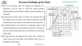
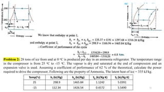
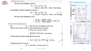
The most convenient chart for studying the behaviour of a
refrigerant is the p-h chart, in which the vertical ordinates
represent pressure and horizontal ordinates represent enthalpy (i.e.
total heat).
A typical chart is shown above. in which a few important lines of
the complete chart are drawn. The saturated liquid line and the
saturated vapour line merge into one another at the critical point.
A saturated liquid is one which has a temperature equal to the
saturation temperature corresponding to its pressure. The space to
the left of the saturated liquid line will, therefore, be sub-cooled
liquid region.
The space between the liquid and the vapour lines is called wet
vapour region and to the right of the saturated vapour line is a
superheated vapour region.
Pressure-Enthalpy (p-h) Chart
7.
Aditya Engineering College(A)
R&AC Dr. Pritam Kumar Das
Aditya Engineering College (A)
7
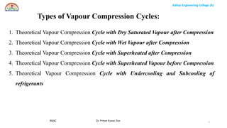
Types of Vapour Compression Cycles:
1. Theoretical Vapour Compression Cycle with Dry Saturated Vapour after Compression
2. Theoretical Vapour Compression Cycle with Wet Vapour after Compression
3. Theoretical Vapour Compression Cycle with Superheated after Compression
4. Theoretical Vapour Compression Cycle with Superheated Vapour before Compression
5. Theoretical Vapour Compression Cycle with Undercooling and Subcooling of
refrigerants
8.
Aditya Engineering College(A)
R&AC Dr. Pritam Kumar Das
Aditya Engineering College (A)
8
1. Theoretical Vapour Compression Cycle with
Dry Saturated Vapour after Compression
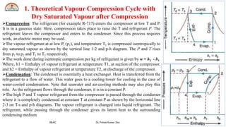
Compression: The refrigerant (for example R-717) enters the compressor at low T and P.
It is in a gaseous state. Here, compression takes place to raise the T and refrigerant P. The
refrigerant leaves the compressor and enters to the condenser. Since this process requires
work, an electric motor may be used.
The vapour refrigerant at at low P, (p1), and temperature T1 is compressed isentropically to
dry saturated vapour as shown by the vertical line 1-2 and p-h diagram. The P and T rises
from p1 to p2 and T1 to T2 respectively.
The work done during isentropic compression per kg of refrigerant is given by w = h2 - h1
Where, h1 = Enthalpy of vapour refrigerant at temperature T1, at suction of the compressor,
and h2 = Enthalpy of vapour refrigerant at temperature T2, at discharge of the compressor.
Condensation: The condenser is essentially a heat exchanger. Heat is transferred from the
refrigerant to a flow of water. This water goes to a cooling tower for cooling in the case of
water-cooled condensation. Note that seawater and air-cooling methods may also play this
role. As the refrigerant flows through the condenser, it is in a constant P.
The high P and T vapour refrigerant from the compressor is passed through the condenser
where it is completely condensed at constant T at constant P as shown by the horizontal line
2-3 on T-s and p-h diagrams. The vapour refrigerant is changed into liquid refrigerant. The
refrigerant, while passing through the condenser gives its latent heat to the surrounding
condensing medium
9.
Aditya Engineering College(A)
R&AC Dr. Pritam Kumar Das
Aditya Engineering College (A)
9
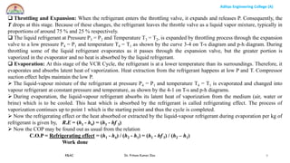
Throttling and Expansion: When the refrigerant enters the throttling valve, it expands and releases P. Consequently, the
T drops at this stage. Because of these changes, the refrigerant leaves the throttle valve as a liquid vapor mixture, typically in
proportions of around 75 % and 25 % respectively.
The liquid refrigerant at Pressure P3 = P2 and Temperature T3 = T2, is expanded by throttling process through the expansion
valve to a low pressure P4 = P1 and temperature T4 = T1 as shown by the curve 3-4 on T-s diagram and p-h diagram. During
throttling some of the liquid refrigerant evaporates as it passes through the expansion valve, but the greater portion is
vaporized in the evaporator and no heat is absorbed by the liquid refrigerant.
Evaporation: At this stage of the VCR Cycle, the refrigerant is at a lower temperature than its surroundings. Therefore, it
evaporates and absorbs latent heat of vaporization. Heat extraction from the refrigerant happens at low P and T. Compressor
suction effect helps maintain the low P.
The liquid-vapour mixture of the refrigerant at pressure P4 = P1 and temperature T4 = T1 is evaporated and changed into
vapour refrigerant at constant pressure and temperature, as shown by the 4-1 on T-s and p-h diagrams.
During evaporation, the liquid-vapour refrigerant absorbs its latent heat of vaporization from the medium (air, water or
brine) which is to be cooled. This heat which is absorbed by the refrigerant is called refrigerating effect. The process of
vaporization continues up to point 1 which is the starting point and thus the cycle is completed.
Now the refrigerating effect or the heat absorbed or extracted by the liquid-vapour refrigerant during evaporation per kg of
refrigerant is given by, R.E = (h1 - h4) = (h1 - hf 3)
Now the COP may be found out as usual from the relation
C.O.P = Refrigerating effect = (h1 - h4) / (h2 - h1) = (h1 - hf 3) / (h2 – h1)
Work done
10.
Aditya Engineering College(A)
R&AC Dr. Pritam Kumar Das
Aditya Engineering College (A)
10
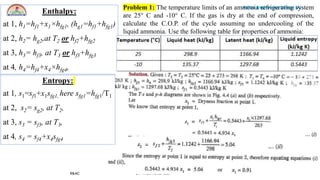
Enthalpy:
at 1, h1=hf1+x1×hfg1, (hg1=hf1+hfg1)
at 2, h2= hg2,at T2 or hf2+hfg2
at 3, h3= hf3, at T3 or hf3+hfg3
at 4, h4=hf4+x4×hfg4,
Entropy:
at 1, s1=sf1+x1sfg1, here sfg1=hfg1/T1
at 2, s2= sg2, at T2,
at 3, s3 = sf3, at T3,
at 4, s4 = sf4+x4sfg4
Problem 1: The temperature limits of an ammonia refrigerating system
are 25° C and -10° C. If the gas is dry at the end of compression,
calculate the C.O.P. of the cycle assuming no undercooling of the
liquid ammonia. Use the following table for properties of ammonia:
11.
Aditya Engineering College(A)
R&AC Dr. Pritam Kumar Das
Aditya Engineering College (A)
11
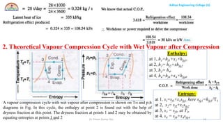
Problem 2: 28 tons of ice from and at 0 oC is produced per day in an ammonia refrigerator. The temperature range
in the compressor is from 25 oC to -15 oC. The vapour is dry and saturated at the end of compression and an
expansion valve is used. Assuming a coefficient of performance of 62 % of the theoretical, calculate the power
required to drive the compressor, Following are the property of Ammonia, The latent heat of ice = 335 kJ/kg.
Temp(oc) hf (kJ/Kg) hg (kJ/Kg) Sg (kJ/Kg K) Sf (kJ/Kg K)
25 298.9 1465.84 1.1242 5.0391
-15 112.34 1426.54 0.4572 5.5490
Aditya Engineering College(A)
R&AC Dr. Pritam Kumar Das 13
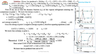
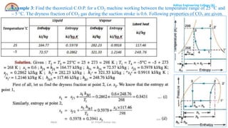
2. Theoretical Vapour Compression Cycle with Wet Vapour after Compression
Enthalpy:
at 1, h1=hf1+x1×hfg1,
at 2, h2= hf2+xhfg2
at 3, h3= h4,
at 4, h4=hf4+x4×hfg4,
Entropy:
at 1, s1=sf1+x1sfg1, here sfg1=hfg1/T1
at 2, s2= sf2+x2sfg2
at 3, s3 = sf3, at T3,
at 4, s4 = sf4+x4sfg4
A vapour compression cycle with wet vapour after compression is shown on T-s and p-h
diagrams in Fig. In this cycle, the enthalpy at point 2 is found out with the help of
dryness fraction at this point. The dryness fraction at points 1 and 2 may be obtained by
equating entropies at points 1 and 2
14.
Aditya Engineering College(A)
R&AC Dr. Pritam Kumar Das 14
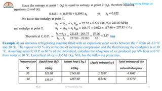
Example 3: Find the theoretical C.O.P. for a CO2 machine working between the temperature range of 25 °C and
– 5 °C. The dryness fraction of CO2 gas during the suction stroke is 0.6. Following properties of CO2 are given.
15.
Aditya Engineering College(A)
R&AC Dr. Pritam Kumar Das 15
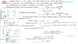
Example 4: An ammonia refrigerating machine fitted with an expansion valve works between the T limits of -10 °C
and 30 °C. The vapour is 95 % dry at the end of isentropic compression and the fluid leaving the condenser is at 30
°C. Assuming actual C.O.P. as 60 % of the theoretical, calculate the kilograms of ice produced per kW hour at 0 °C
from water at 10 °C. Latent heat of ice is 335 kJ / kg. NH3 has the following properties.
Aditya Engineering College(A)
R&AC Dr. Pritam Kumar Das 17
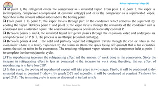
3. Theoretical Vapour Compression Cycle with superheated vapour after Compression
Enthalpy:
at 2, h2= hg2+Cpg (T2-T2’)
at 4, h4=hf4+x4×hfg4,
Entropy:
at 2, s2= sg2+Cpgln(T2/T2’)
at 4, s4 = sf4+x4sfg4
•A vapour compression cycle with superheated vapour after compression is shown on T-s and p-h diagrams in Fig.
In this cycle, the enthalpy at point 2 is found out with the help of degree of superheat. The degree of superheat
may be found out by equating the entropies at points 1 and 2. Now the coefficient of performance may be found
out as usual from the relation
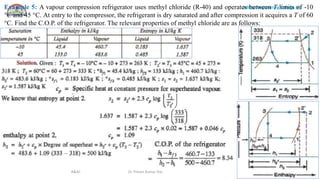
18.
Aditya Engineering College(A)
R&AC Dr. Pritam Kumar Das 18
At point 1, the refrigerant enters the compressor as a saturated vapor. From point 1 to point 2, the vapor is
isentropically compressed (compressed at constant entropy) and exits the compressor as a superheated vapor.
Superheat is the amount of heat added above the boiling point.
From point 2 to point 2’, the vapor travels through part of the condenser which removes the superheat by
cooling the vapor. Between point 2’ and point 3, the vapor travels through the remainder of the condenser and is
condensed into a saturated liquid. The condensation process occurs at essentially constant P.
Between points 3 and 4, the saturated liquid refrigerant passes through the expansion valve and undergoes an
abrupt decrease of P & T. The process is isenthalpic (constant enthalpy).
Between points 4 and 1, the cold and partially vaporized refrigerant travels through the coil or tubes in the
evaporator where it is totally vaporized by the warm air (from the space being refrigerated) that a fan circulates
across the coil or tubes in the evaporator. The resulting refrigerant vapor returns to the compressor inlet at point 1
to complete the thermodynamic cycle.
The superheating increases the refrigerating effect and the amount of work done in the compressor. Since the
increase in refrigerating effect is less as compared to the increase in work done, therefore, the net effect of
superheating is to have low COP.
In this cycle, the cooling of superheated vapour will take place in two stages. Firstly, it will be condensed to dry
saturated stage at constant P (shown by graph 2-2') and secondly, it will be condensed at constant T (shown by
graph 2'-3). The remaining cycle is same as discussed in the last article
19.
Aditya Engineering College(A)
R&AC Dr. Pritam Kumar Das 19
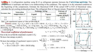
Example 5: A vapour compression refrigerator uses methyl chloride (R-40) and operates between T limits of -10
°C and 45 °C. At entry to the compressor, the refrigerant is dry saturated and after compression it acquires a T of 60
°C. Find the C.O.P. of the refrigerator. The relevant properties of methyl chloride are as follows:
20.
Aditya Engineering College(A)
R&AC Dr. Pritam Kumar Das 20
Problem 6: A refrigeration machine using R-12 as refrigerant operates between the P of 2.5 bar and 9 bar. The
compression is isentropic and there is no undercooling in the condenser. The vapour is in dry saturated condition at
the beginning of the compression. Estimate the theoretical COP. If the actual COP is 0.65 of theoretical value,
calculate the net cooling produced per hour. The refrigerant flow is 5 kg per minute. Properties of refrigerant are:
21.
Aditya Engineering College(A)
R&AC Dr. Pritam Kumar Das 21
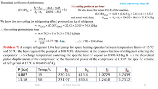
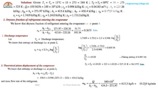
Problem 7: A simple refrigerant 134a heat pump for space heating operates between temperature limits of 15 0C
and 50 0C. the heat required the pumped is 100 MJ/h. determine: i) the dryness fraction of refrigerant entering the
evaporator ii) discharge temperature assuming the specific heat of vapour as 0.996 KJ/Kg K iii) the theoretical
piston displacement of the compressor iv) the theoretical power of the compressor v) C.O.P. the specific volume
of refrigerant at 15 0C is 0.04185 m3/kg.
Aditya Engineering College(A)
R&AC Dr. Pritam Kumar Das 23
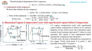
4. Theoretical Vapour Compression Cycle with superheated vapour before Compression
A vapour compression cycle with superheated
vapour before compression is shown on T-s and p-h
diagrams in Fig. In this cycle, the evaporation starts
at point 4 and continues upto point 1', when it is dry
saturated. The vapour is now superheated before
entering the compressor upto the point 1.
In this cycle, the heat is absorbed (or extracted) in
two stages. Firstly from point 4 to point 1‘ and
secondly from point 1' to point 1.
Aditya Engineering College(A)
R&AC Dr. Pritam Kumar Das 25
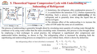
5. Theoretical Vapour Compression Cycle with Undercooling or
Subcooling of Refrigerant
Sometimes, the refrigerant, after condensation process 2’ -
3’, is cooled below the saturation T (T3’) before expansion by
throttling. Such a process is called undercooling of the
refrigerant and is generally done along the liquid line as
shown in Figure.
The ultimate effect of the undercooling is to increase the
value of COP under the same set of conditions.
The process of undercooling is generality brought about by circulating more quantity of cooling water through the
condenser or by using water colder than the main circulating water. Sometimes, this process is also brought about
by employing a heat exchanger. In actual practice, the refrigerant is superheated after compression and
undercooled before throttling, as shown in Fig. The refrigerating effect is increased by adopting both the
superheating and undercooling process as compared to a cycle without them, which is shown by dotted line.
26.
Aditya Engineering College(A)
R&AC Dr. Pritam Kumar Das 26
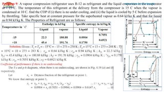
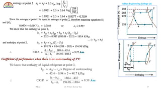
Problem 9: A vapour compression refrigerator uses R-12 as refrigerant and the liquid evaporates in the evaporator
at - 15 C. The temperature of this refrigerant at the delivery from the compressor is 15 C when the vapour is
condensed at 10 C. find the COP if (i) there is no under cooling, and (ii) the liquid is cooled by 5 C before expansion
by throttling. Take specific heat at constant pressure for the superheated vapour as 0.64 kJ/kg K and that for liquid
as 0.94 kJ/kg K. The Properties of Refrigerant are as follows:
Aditya Engineering College(A)
R&AC Dr. Pritam Kumar Das 28
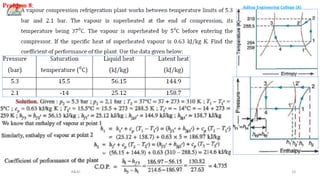
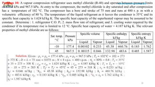
Problem 10: A vapour compression refrigerator uses methyl chloride (R-40) and operates between pressure limits
of 177.4 kPa and 967.5 kPa. At entry to the compressor, the methyl chloride is dry saturated and after compression
has a temperature of 102 °C. The compressor has a bore and stroke of 75 mm and runs at 480 r. p. m with a
volumetric efficiency of 80 %. The temperature of the liquid refrigerant as it leaves the condenser is 35°C and its
specific heat capacity is 1.624 kJ/kg K. The specific heat capacity of the superheated vapour may be assumed to be
constant. Determine : 1. refrigerator C.O. P.; 2. mass flow rate of refrigerant; and 3. cooling water required by the
condenser if its temperature rise is limited to 12 °C. Specific heat capacity of water = 4.187 kJ/kg K. The relevant
properties of methyl chloride are as follows:
Sat. temp.
° C
Pressure
kPa
Specific volume Specific enthalpy
kJ/kg
Specific entropy
kJ/kg K
Liquid Vapour Liquid Vapour Liquid Vapour
-10 177.4 0.00102 0.233 45.38 460.76 0.183 1.762
45 967.5 0. 00115 0.046 132.98 483.6 0.485 1.587
Aditya Engineering College(A)
R&AC Dr. Pritam Kumar Das 30
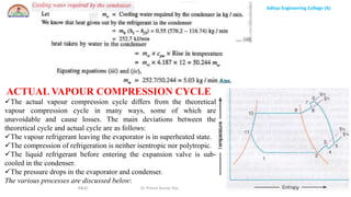
ACTUAL VAPOUR COMPRESSION CYCLE
The actual vapour compression cycle differs from the theoretical
vapour compression cycle in many ways, some of which are
unavoidable and cause losses. The main deviations between the
theoretical cycle and actual cycle are as follows:
The vapour refrigerant leaving the evaporator is in superheated state.
The compression of refrigeration is neither isentropic nor polytropic.
The liquid refrigerant before entering the expansion valve is sub-
cooled in the condenser.
The pressure drops in the evaporator and condenser.
The various processes are discussed below:
31.
Aditya Engineering College(A)
R&AC Dr. Pritam Kumar Das 31
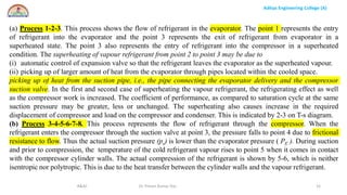
(a) Process 1-2-3. This process shows the flow of refrigerant in the evaporator. The point 1 represents the entry
of refrigerant into the evaporator and the point 3 represents the exit of refrigerant from evaporator in a
superheated state. The point 3 also represents the entry of refrigerant into the compressor in a superheated
condition. The superheating of vapour refrigerant from point 2 to point 3 may be due to
(i) automatic control of expansion valve so that the refrigerant leaves the evaporator as the superheated vapour.
(ii) picking up of larger amount of heat from the evaporator through pipes located within the cooled space.
picking up of heat from the suction pipe, i.e., the pipe connecting the evaporator delivery and the compressor
suction valve. In the first and second case of superheating the vapour refrigerant, the refrigerating effect as well
as the compressor work is increased. The coefficient of performance, as compared to saturation cycle at the same
suction pressure may be greater, less or unchanged. The superheating also causes increase in the required
displacement of compressor and load on the compressor and condenser. This is indicated by 2-3 on T-s diagram.
(b) Process 3-4-5-6-7-8. This process represents the flow of refrigerant through the compressor. When the
refrigerant enters the compressor through the suction valve at point 3, the pressure falls to point 4 due to frictional
resistance to flow. Thus the actual suction pressure (ps) is lower than the evaporator pressure ( PE ). During suction
and prior to compression, the temperature of the cold refrigerant vapour rises to point 5 when it comes in contact
with the compressor cylinder walls. The actual compression of the refrigerant is shown by 5-6, which is neither
isentropic nor polytropic. This is due to the heat transfer between the cylinder walls and the vapour refrigerant.
32.
Aditya Engineering College(A)
R&AC Dr. Pritam Kumar Das 32
The temperature of the cylinder walls is some-what in between the temperatures of cold suction vapour
refrigerant and hot discharge vapour refrigerant. It may be assumed that the heat absorbed by the vapour
refrigerant from the cylinder walls during the first part of the compression stroke is equal to heat rejected by the
vapour refrigerant to the cylinder walls. Like the heating effect at suction given by 4-5, there is a cooling effect at
discharge as given by 6-7. These heating and cooling effects take place at constant pressure. Due to the frictional
resistance of flow, there is a pressure drop i.e., the actual discharge pressure.( pD) is more than the condenser
pressure ( pC).
(c) Process 8-9-10-11. This process represents the flow of refrigerant though the condenser. The process 8-9
represents the cooling of superheated vapour refrigerant to the dry saturated state. The process 9-10 shows the
removal of latent heat which changes the dry saturated refrigerant into liquid refrigerant. The process 10-11
represents the sub-cooling of liquid refrigerant in the condenser before passing through the expansion valve.
This is desirable as it increases the refrigerating effect per kg of the refrigerant flow. It also reduces the
volume of the refrigerant partially evaporated from the liquid refrigerant while passing through the expansion
valve. The increase in refrigerating effect can be obtained by large quantities of circulating cooling water which
should be at a temperature much lower than the condensing temperatures.
(d) Process 11-1. This process represents the expansion of subcooled liquid refrigerant by throttling from the
condenser pressure to the evaporator pressure.
33.
Aditya Engineering College(A)
R&AC Dr. Pritam Kumar Das 33
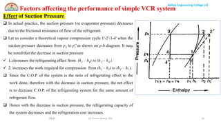
Factors affecting the performance of simple VCR system
Effect of Suction Pressure
In actual practice, the suction pressure (or evaporator pressure) decreases
due to the frictional resistance of flow of the refrigerant.
Let us consider a theoretical vapour compression cycle 1'-2'-3-4' when the
suction pressure decreases from pS to ps' as shown on p-h diagram. It may
be noted that the decrease in suction pressure
1. decreases the refrigerating effect from (h1 – h4) to (h1’– h4’).
2. increases the work required for compression from (h2 – h1) to (h2' – h1’).
Since the C.O.P. of the system is the ratio of refrigerating effect to the
work done, therefore with the decrease in suction pressure, the net effect
is to decrease C.O.P. of the refrigerating system for the same amount of
refrigerant flow.
Hence with the decrease in suction pressure, the refrigerating capacity of
the system decreases and the refrigeration cost increases.
34.
Aditya Engineering College(A)
R&AC Dr. Pritam Kumar Das 34
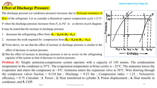
Effect of Discharge Pressure:
The discharge pressure (or condenser pressure) increases due to frictional resistance of
flow of the refrigerant. Let us consider a theoretical vapour compression cycle 1-2'-3'-
4' when the discharge pressure increases from Pd to Pd’ to as shown on p-h diagram.
It may be noted that the increase in discharge pressure
1. decreases the refrigerating effect from (h1 – h4) to (h1– h4’).
2. increases the work required for compression from (h2 – h1) to (h2' – h1’).
From above, we see that the effect of increase in discharge pressure is similar to the
effect of decrease in suction pressure.
But the effect of increase in discharge pressure is not as severe on the refrigerating
capacity of the system as that of decrease in suction pressure.
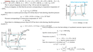
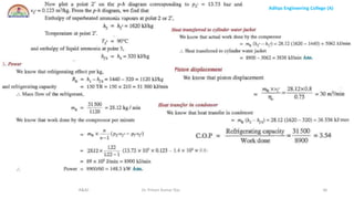
Problem 11: Simple ammonia-compression system operates with a capacity of 150 tonnes. The condensation
temperature in the condenser is 35°C. The evaporation temperature in brine cooler is - 25°C. The ammonia leaves the
evaporator and enters the compressor at - 8°C. Ammonia enters the expansion valve at 30°C. Wire drawing through
the compressor valves Suction = 0.118 bar ; Discharge = 0.23 bar ; Compression index = 1.22 ; Volumetric
efficiency = 0.75. Calculate : 1. Power ; 2. Heat transferred to cylinder 3. Piston displacement ; 4. Heat transfer in
condenser; and 5. COP.