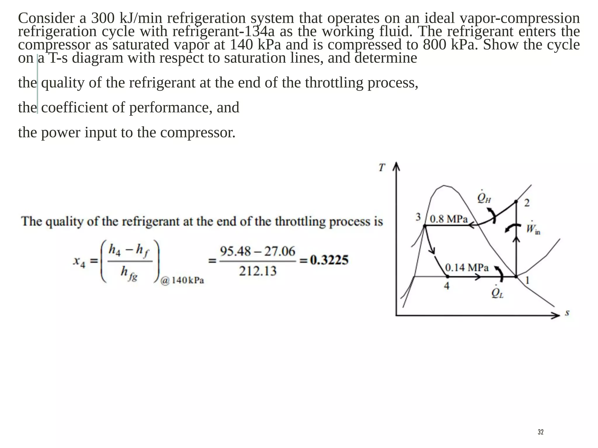
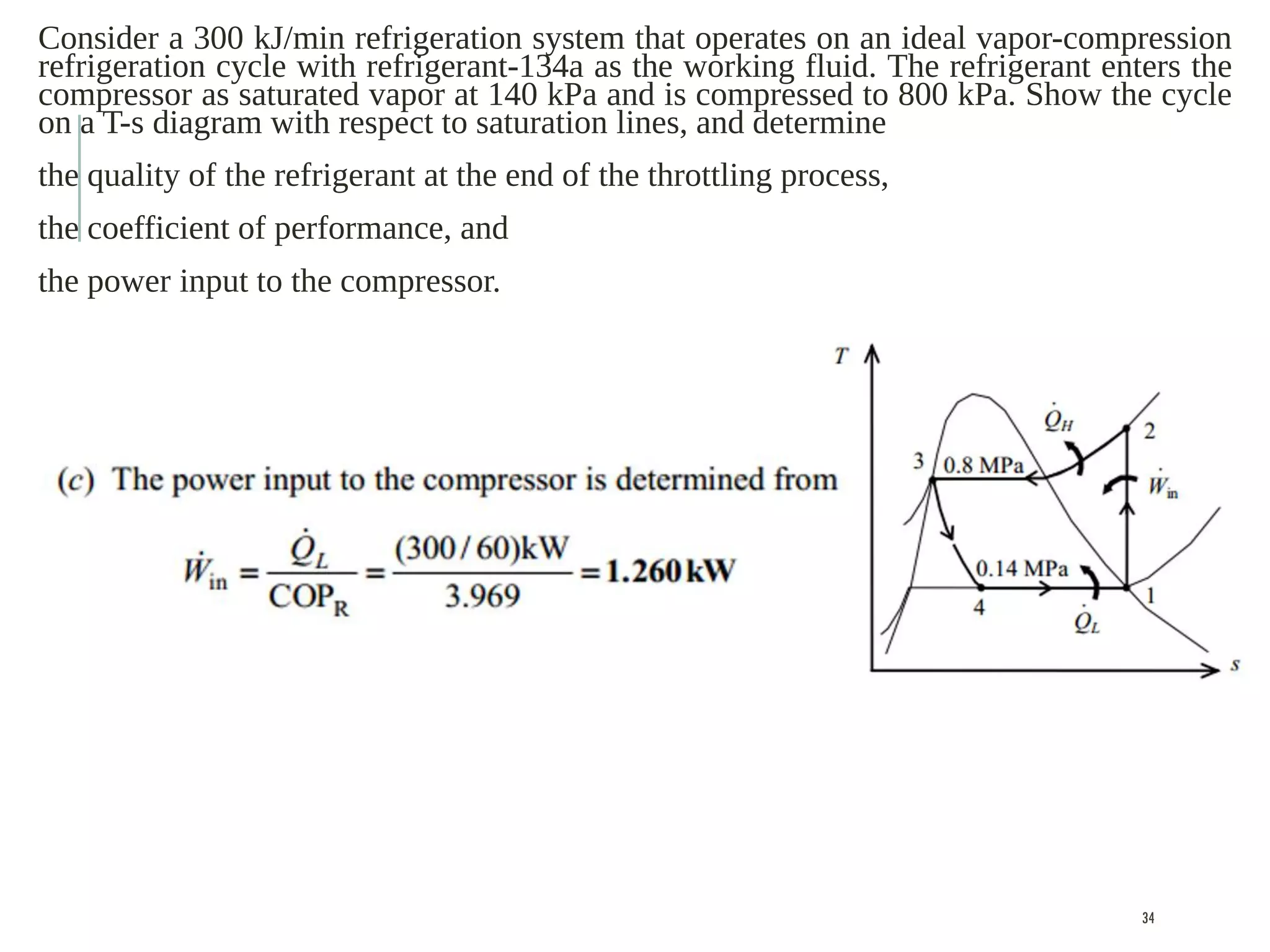
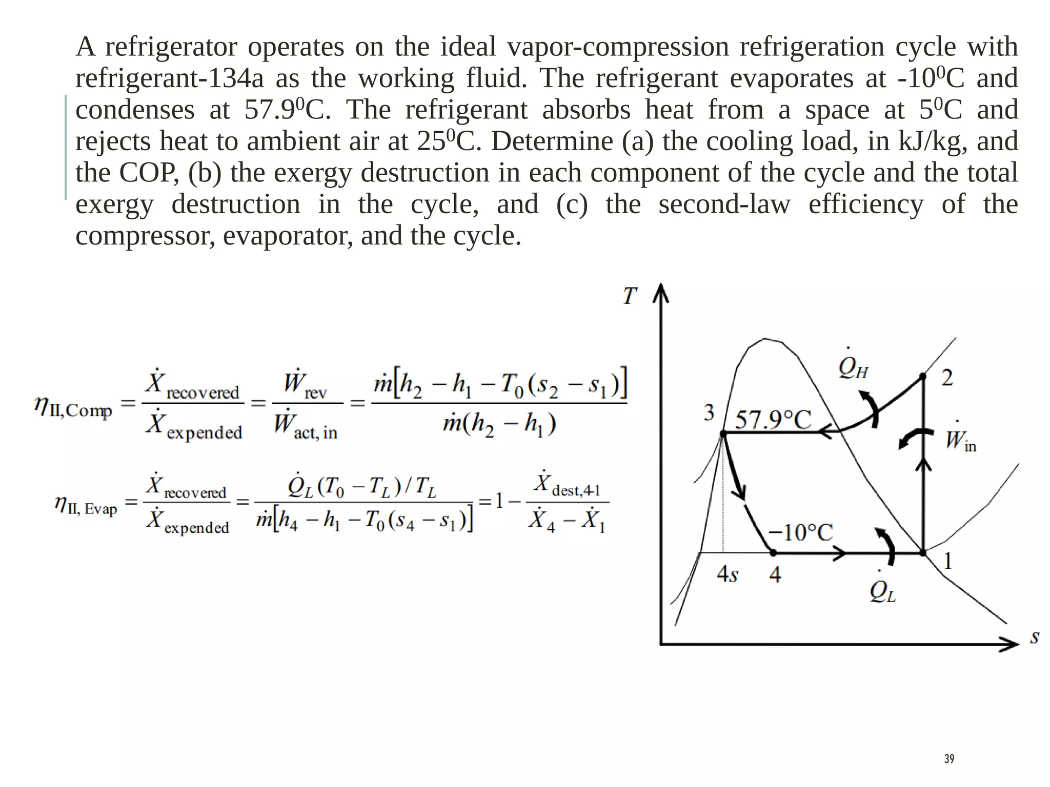
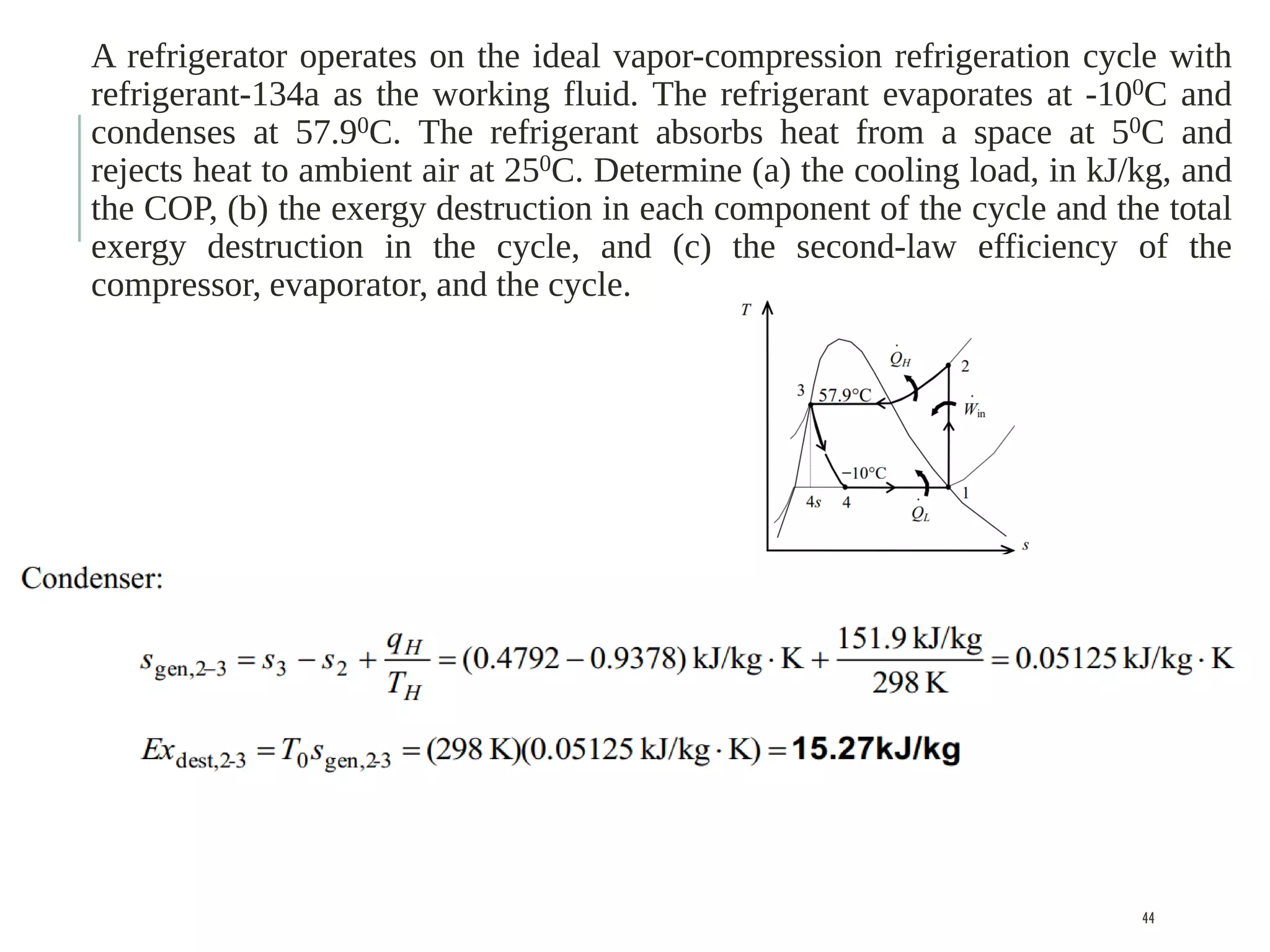
REFRIGERATION CYCLES
Chapter-11, Thermodynamics- An Engineering Approach
Y A Cengel and M A Boles
1
A major application area of thermodynamics is refrigeration, transfer of heat from a
lower temperature region to a higher temperature one.
Devices that produce refrigeration are called refrigerators, and the cycles on which
they operate are called refrigeration cycles.
2
The most frequently used refrigeration cycle is the vapor-compression refrigeration
cycle in which the refrigerant is vaporized and condensed alternately and is
compressed in the vapor phase.
Another well-known refrigeration cycle, and is the gas refrigeration cycle in which
the refrigerant remains in the gaseous phase throughout.
Other refrigeration cycles discussed in this chapter are cascade refrigeration, where
more than one refrigeration cycle is used
and absorption refrigeration, where the refrigerant is dissolved in a liquid before it is
compressed.
3
REFRIGERATORS AND HEAT PUMPS
The objective of a refrigerator is to maintain the
refrigerated space at a low temperature by removing
heat from it. Discharging this heat to a higher-
temperature medium is merely a necessary part of the
operation, not the purpose. The objective of a heat
pump, however, is to maintain a heated space at a
high temperature. This is accomplished by absorbing
heat from a low-temperature source, such as well water
or cold outside air in winter, and supplying this heat to
a warmer medium such as a house.
4
COEFFICIENT OF PERFORMANCE (COP)
The performance of refrigerators and heat pumps is expressed in terms
of the Coefficient of performance(COP), defined as
5
TON OF REFRIGERATION (TOR)
The cooling capacity of a refrigeration system—that is, the rate of heat removal
from the refrigerated space—is often expressed in terms of tons of refrigeration.
The capacity of a refrigeration system that can freeze 1 ton (2000 lbm) of liquid
water at 0°C (32°F) into ice at 0°C in 24 h is said to be 1 ton. One ton of
refrigeration is equivalent to 211 kJ/min (3.52 kW).
The cooling load of a typical 200-m2 residence is in the 3-ton (10-kW) range.
6
THE IDEAL VAPOR-COMPRESSION
REFRIGERATION CYCLE
7
THE IDEAL VAPOR-COMPRESSION
REFRIGERATION CYCLE
In a household refrigerator, the tubes in the freezer
compartment where heat is absorbed by the
refrigerant serves as the evaporator. The coils
behind the refrigerator, where heat is dissipated to
the kitchen air, serve as the condenser (Fig. 11–4).
8
THE IDEAL VAPOR-COMPRESSION
REFRIGERATION CYCLE
Remember that the area under the process curve on a
T-s diagram represents the heat transfer for
internally reversible processes. The area under the
process curve 4-1 represents the heat absorbed by
the refrigerant in the evaporator, and the area under
the process curve 2-3 represents the heat rejected in
the condenser. A rule of thumb is that the COP
improves by 2 to 4 percent for each °C the
evaporating temperature is raised or the condensing
temperature is lowered.
9
THE IDEAL VAPOR-COMPRESSION
REFRIGERATION CYCLE
On P-h diagram, three of the four processes
appear as straight lines, and the heat transfer in
the condenser and the evaporator is
proportional to the lengths of the corresponding
process curves.
10
THE IDEAL VAPOR-COMPRESSION
REFRIGERATION CYCLE
The ideal vapor compression refrigeration cycle is not an
internally reversible cycle since it involves an irreversible
(throttling) process.
This process is maintained in the cycle to make it a more
realistic model for the actual vapor-compression refrigeration
cycle. If the throttling device were replaced by an isentropic
turbine, the refrigerant would enter the evaporator at state 4’
instead of state 4.
11
THE IDEAL VAPOR-COMPRESSION
REFRIGERATION CYCLE
As a result, the refrigeration capacity would increase (by the
area under process curve 4’-4 in Fig.) and the net work input
would decrease (by the amount of work output of the
turbine).
Replacing the expansion valve by a turbine is not practical,
however, since the added benefits cannot justify the added
cost and complexity.
12
THE IDEAL VAPOR-COMPRESSION
REFRIGERATION CYCLE
The condenser and the evaporator do not involve any work, and the
compressor can be approximated as adiabatic. Then the COPs of
refrigerators and heat pumps operating on the vapor-compression
refrigeration cycle can be expressed as
13
ACTUAL VAPOR-COMPRESSION
REFRIGERATION CYCLE
An actual vapor-compression refrigeration cycle differs
from the ideal one in several ways, owing mostly to the
irreversibilities that occur in various components. Two
common sources of irreversibilities are fluid friction
(causes pressure drops) and heat transfer to or from the
surroundings. The T-s diagram of an actual vapor-
compression refrigeration cycle is shown in Fig.
14
ACTUAL VAPOR-COMPRESSION
REFRIGERATION CYCLE
In the ideal cycle, the refrigerant leaves the evaporator
and enters the compressor as saturated vapor. In practice,
however, it may not be possible to control the state of the
refrigerant so precisely. Instead, it is easier to design the
system so that the refrigerant is slightly superheated at
the compressor inlet. This slight overdesign ensures that
the refrigerant is completely vaporized when it enters the
compressor.
15
ACTUAL VAPOR-COMPRESSION
REFRIGERATION CYCLE
Also, the line connecting the evaporator to the
compressor is usually very long; thus the pressure drop
caused by fluid friction and heat transfer from the
surroundings to the refrigerant can be very significant.
The result of superheating, heat gain in the connecting
line, and pressure drops in the evaporator and the
connecting line is an increase in the specific volume,
thus an increase in the power input requirements to the
compressor since steady-flow work is proportional to
the specific volume.
16
ACTUAL VAPOR-COMPRESSION
REFRIGERATION CYCLE
The compression process in the ideal cycle is internally
reversible and adiabatic, and thus isentropic. The actual
compression process, however, involves frictional
effects, which increase the entropy, and heat transfer,
which may increase or decrease the entropy, depending
on the direction.
Therefore, the entropy of the refrigerant may increase
(process 1-2) or decrease (process 1-2’) during an actual
compression process, depending on which effects
dominate.
17
ACTUAL VAPOR-COMPRESSION
REFRIGERATION CYCLE
The compression process 1-2’ may be even more
desirable than the isentropic compression process since
the specific volume of the refrigerant and thus the work
input requirement are smaller in this case.
Therefore, the refrigerant should be cooled during the
compression process whenever it is practical and
economical to do so.
18
ACTUAL VAPOR-COMPRESSION
REFRIGERATION CYCLE
In the ideal case, the refrigerant is assumed to leave the
condenser as saturated liquid at the compressor exit
pressure. In reality, however, it is unavoidable to have some
pressure drop in the condenser as well as in the lines
connecting the condenser to the compressor and to the
throttling valve.
Also, it is not easy to execute the condensation process with
such precision that the refrigerant is a saturated liquid at the
end, and it is undesirable to route the refrigerant to the
throttling valve before the refrigerant is completely
condensed.
19
ACTUAL VAPOR-COMPRESSION
REFRIGERATION CYCLE
Therefore, the refrigerant is subcooled somewhat before it
enters the throttling valve. Since the refrigerant in this case
enters the evaporator with a lower enthalpy and thus can
absorb more heat from the refrigerated space.
The throttling valve and the evaporator are usually located
very close to each other, so the pressure drop in the
connecting line is small.
20
SELECTING THE RIGHT REFRIGERANT
Home reading
21
An ideal vapor-compression refrigeration cycle that
uses refrigerant-134a as its working fluid maintains a
condenser at 800 kPa and the evaporator at -12°C.
Determine this system’s COP and the amount of
power required to service a 150 kW cooling load.
22
An ideal vapor-compression refrigeration
cycle that uses refrigerant-134a as its
working fluid maintains a condenser at 800
kPa and the evaporator at -12°C. Determine
this system’s COP and the amount of power
required to service a 150 kW cooling load.
23
An ideal vapor-compression refrigeration
cycle that uses refrigerant-134a as its
working fluid maintains a condenser at 800
kPa and the evaporator at -12°C. Determine
this system’s COP and the amount of power
required to service a 150 kW cooling load.
24
An ideal vapor-compression refrigeration
cycle that uses refrigerant-134a as its
working fluid maintains a condenser at 800
kPa and the evaporator at -12°C. Determine
this system’s COP and the amount of power
required to service a 150 kW cooling load.
25
An ideal vapor-compression refrigeration
cycle that uses refrigerant-134a as its
working fluid maintains a condenser at 800
kPa and the evaporator at -12°C. Determine
this system’s COP and the amount of power
required to service a 150 kW cooling load.
26
An ideal vapor-compression refrigeration
cycle that uses refrigerant-134a as its
working fluid maintains a condenser at 800
kPa and the evaporator at -12°C. Determine
this system’s COP and the amount of power
required to service a 150 kW cooling load.
27
Consider a 300 kJ/min refrigeration system that
operates on an ideal vapor-compression refrigeration
cycle with refrigerant-134a as the working fluid. The
refrigerant enters the compressor as saturated vapor at
140 kPa and is compressed to 800 kPa. Show the
cycle on a T-s diagram with respect to saturation lines,
and determine
the quality of the refrigerant at the end of the
throttling process,
the coefficient of performance, and
the power input to the compressor.
28
Consider a 300 kJ/min refrigeration system that operates on an ideal vapor-compression
refrigeration cycle with refrigerant-134a as the working fluid. The refrigerant enters the
compressor as saturated vapor at 140 kPa and is compressed to 800 kPa. Show the cycle
on a T-s diagram with respect to saturation lines, and determine
the quality of the refrigerant at the end of the throttling process,
the coefficient of performance, and
the power input to the compressor.
29
Consider a 300 kJ/min refrigeration system that operates on an ideal vapor-compression
refrigeration cycle with refrigerant-134a as the working fluid. The refrigerant enters the
compressor as saturated vapor at 140 kPa and is compressed to 800 kPa. Show the cycle
on a T-s diagram with respect to saturation lines, and determine
the quality of the refrigerant at the end of the throttling process,
the coefficient of performance, and
the power input to the compressor.
30
Consider a 300 kJ/min refrigeration system that operates on an ideal vapor-compression
refrigeration cycle with refrigerant-134a as the working fluid. The refrigerant enters the
compressor as saturated vapor at 140 kPa and is compressed to 800 kPa. Show the cycle
on a T-s diagram with respect to saturation lines, and determine
the quality of the refrigerant at the end of the throttling process,
the coefficient of performance, and
the power input to the compressor.
31
Consider a 300 kJ/min refrigeration system that operates on an ideal vapor-compression
refrigeration cycle with refrigerant-134a as the working fluid. The refrigerant enters the
compressor as saturated vapor at 140 kPa and is compressed to 800 kPa. Show the cycle
on a T-s diagram with respect to saturation lines, and determine
the quality of the refrigerant at the end of the throttling process,
the coefficient of performance, and
the power input to the compressor.
32
Consider a 300 kJ/min refrigeration system that operates on an ideal vapor-compression
refrigeration cycle with refrigerant-134a as the working fluid. The refrigerant enters the
compressor as saturated vapor at 140 kPa and is compressed to 800 kPa. Show the cycle
on a T-s diagram with respect to saturation lines, and determine
the quality of the refrigerant at the end of the throttling process,
the coefficient of performance, and
the power input to the compressor.
33
Consider a 300 kJ/min refrigeration system that operates on an ideal vapor-compression
refrigeration cycle with refrigerant-134a as the working fluid. The refrigerant enters the
compressor as saturated vapor at 140 kPa and is compressed to 800 kPa. Show the cycle
on a T-s diagram with respect to saturation lines, and determine
the quality of the refrigerant at the end of the throttling process,
the coefficient of performance, and
the power input to the compressor.
34
A refrigerator operates on the ideal vapor-compression refrigeration cycle with
refrigerant-134a as the working fluid. The refrigerant evaporates at -100C and
condenses at 57.90C. The refrigerant absorbs heat from a space at 50C and rejects
heat to ambient air at 250C. Determine (a) the cooling load, in kJ/kg, and the COP,
(b) the exergy destruction in each component of the cycle and the total exergy
destruction in the cycle, and (c) the second-law efficiency of the compressor,
evaporator, and the cycle.
35
A refrigerator operates on the ideal vapor-compression refrigeration cycle with
refrigerant-134a as the working fluid. The refrigerant evaporates at -100C and
condenses at 57.90C. The refrigerant absorbs heat from a space at 50C and
rejects heat to ambient air at 250C. Determine (a) the cooling load, in kJ/kg, and
the COP, (b) the exergy destruction in each component of the cycle and the total
exergy destruction in the cycle, and (c) the second-law efficiency of the
compressor, evaporator, and the cycle.
36
A refrigerator operates on the ideal vapor-compression refrigeration cycle with
refrigerant-134a as the working fluid. The refrigerant evaporates at -100C and
condenses at 57.90C. The refrigerant absorbs heat from a space at 50C and
rejects heat to ambient air at 250C. Determine (a) the cooling load, in kJ/kg, and
the COP, (b) the exergy destruction in each component of the cycle and the total
exergy destruction in the cycle, and (c) the second-law efficiency of the
compressor, evaporator, and the cycle.
37
A refrigerator operates on the ideal vapor-compression refrigeration cycle with
refrigerant-134a as the working fluid. The refrigerant evaporates at -100C and
condenses at 57.90C. The refrigerant absorbs heat from a space at 50C and
rejects heat to ambient air at 250C. Determine (a) the cooling load, in kJ/kg, and
the COP, (b) the exergy destruction in each component of the cycle and the total
exergy destruction in the cycle, and (c) the second-law efficiency of the
compressor, evaporator, and the cycle.
Another expression,
38
A refrigerator operates on the ideal vapor-compression refrigeration cycle with
refrigerant-134a as the working fluid. The refrigerant evaporates at -100C and
condenses at 57.90C. The refrigerant absorbs heat from a space at 50C and
rejects heat to ambient air at 250C. Determine (a) the cooling load, in kJ/kg, and
the COP, (b) the exergy destruction in each component of the cycle and the total
exergy destruction in the cycle, and (c) the second-law efficiency of the
compressor, evaporator, and the cycle.
39
A refrigerator operates on the ideal vapor-compression refrigeration cycle with
refrigerant-134a as the working fluid. The refrigerant evaporates at -100C and
condenses at 57.90C. The refrigerant absorbs heat from a space at 50C and
rejects heat to ambient air at 250C. Determine (a) the cooling load, in kJ/kg, and
the COP, (b) the exergy destruction in each component of the cycle and the total
exergy destruction in the cycle, and (c) the second-law efficiency of the
compressor, evaporator, and the cycle.
40
A refrigerator operates on the ideal vapor-compression refrigeration cycle with
refrigerant-134a as the working fluid. The refrigerant evaporates at -100C and
condenses at 57.90C. The refrigerant absorbs heat from a space at 50C and
rejects heat to ambient air at 250C. Determine (a) the cooling load, in kJ/kg, and
the COP, (b) the exergy destruction in each component of the cycle and the total
exergy destruction in the cycle, and (c) the second-law efficiency of the
compressor, evaporator, and the cycle.
41
A refrigerator operates on the ideal vapor-compression refrigeration cycle with
refrigerant-134a as the working fluid. The refrigerant evaporates at -100C and
condenses at 57.90C. The refrigerant absorbs heat from a space at 50C and
rejects heat to ambient air at 250C. Determine (a) the cooling load, in kJ/kg, and
the COP, (b) the exergy destruction in each component of the cycle and the total
exergy destruction in the cycle, and (c) the second-law efficiency of the
compressor, evaporator, and the cycle.
42
A refrigerator operates on the ideal vapor-compression refrigeration cycle with
refrigerant-134a as the working fluid. The refrigerant evaporates at -100C and
condenses at 57.90C. The refrigerant absorbs heat from a space at 50C and
rejects heat to ambient air at 250C. Determine (a) the cooling load, in kJ/kg, and
the COP, (b) the exergy destruction in each component of the cycle and the total
exergy destruction in the cycle, and (c) the second-law efficiency of the
compressor, evaporator, and the cycle.
43
A refrigerator operates on the ideal vapor-compression refrigeration cycle with
refrigerant-134a as the working fluid. The refrigerant evaporates at -100C and
condenses at 57.90C. The refrigerant absorbs heat from a space at 50C and
rejects heat to ambient air at 250C. Determine (a) the cooling load, in kJ/kg, and
the COP, (b) the exergy destruction in each component of the cycle and the total
exergy destruction in the cycle, and (c) the second-law efficiency of the
compressor, evaporator, and the cycle.
44
A refrigerator operates on the ideal vapor-compression refrigeration cycle with
refrigerant-134a as the working fluid. The refrigerant evaporates at -100C and
condenses at 57.90C. The refrigerant absorbs heat from a space at 50C and
rejects heat to ambient air at 250C. Determine (a) the cooling load, in kJ/kg, and
the COP, (b) the exergy destruction in each component of the cycle and the total
exergy destruction in the cycle, and (c) the second-law efficiency of the
compressor, evaporator, and the cycle.
45
A refrigerator operates on the ideal vapor-compression refrigeration cycle with
refrigerant-134a as the working fluid. The refrigerant evaporates at -100C and
condenses at 57.90C. The refrigerant absorbs heat from a space at 50C and
rejects heat to ambient air at 250C. Determine (a) the cooling load, in kJ/kg, and
the COP, (b) the exergy destruction in each component of the cycle and the total
exergy destruction in the cycle, and (c) the second-law efficiency of the
compressor, evaporator, and the cycle.
46
A refrigerator operates on the ideal vapor-compression refrigeration cycle with
refrigerant-134a as the working fluid. The refrigerant evaporates at -100C and
condenses at 57.90C. The refrigerant absorbs heat from a space at 50C and
rejects heat to ambient air at 250C. Determine (a) the cooling load, in kJ/kg, and
the COP, (b) the exergy destruction in each component of the cycle and the total
exergy destruction in the cycle, and (c) the second-law efficiency of the
compressor, evaporator, and the cycle.
47
A refrigerator operates on the ideal vapor-compression refrigeration cycle with
refrigerant-134a as the working fluid. The refrigerant evaporates at -100C and
condenses at 57.90C. The refrigerant absorbs heat from a space at 50C and
rejects heat to ambient air at 250C. Determine (a) the cooling load, in kJ/kg, and
the COP, (b) the exergy destruction in each component of the cycle and the total
exergy destruction in the cycle, and (c) the second-law efficiency of the
compressor, evaporator, and the cycle.
48
A refrigerator operates on the ideal vapor-compression refrigeration cycle with
refrigerant-134a as the working fluid. The refrigerant evaporates at -100C and
condenses at 57.90C. The refrigerant absorbs heat from a space at 50C and
rejects heat to ambient air at 250C. Determine (a) the cooling load, in kJ/kg, and
the COP, (b) the exergy destruction in each component of the cycle and the total
exergy destruction in the cycle, and (c) the second-law efficiency of the
compressor, evaporator, and the cycle.
49
A refrigerator operates on the ideal vapor-compression refrigeration cycle with
refrigerant-134a as the working fluid. The refrigerant evaporates at -100C and
condenses at 57.90C. The refrigerant absorbs heat from a space at 50C and
rejects heat to ambient air at 250C. Determine (a) the cooling load, in kJ/kg, and
the COP, (b) the exergy destruction in each component of the cycle and the total
exergy destruction in the cycle, and (c) the second-law efficiency of the
compressor, evaporator, and the cycle.
50
A refrigerator operates on the ideal vapor-compression refrigeration cycle with
refrigerant-134a as the working fluid. The refrigerant evaporates at -100C and
condenses at 57.90C. The refrigerant absorbs heat from a space at 50C and
rejects heat to ambient air at 250C. Determine (a) the cooling load, in kJ/kg, and
the COP, (b) the exergy destruction in each component of the cycle and the total
exergy destruction in the cycle, and (c) the second-law efficiency of the
compressor, evaporator, and the cycle.
51
A refrigerator operates on the ideal vapor-compression refrigeration cycle with
refrigerant-134a as the working fluid. The refrigerant evaporates at -100C and
condenses at 57.90C. The refrigerant absorbs heat from a space at 50C and
rejects heat to ambient air at 250C. Determine (a) the cooling load, in kJ/kg, and
the COP, (b) the exergy destruction in each component of the cycle and the total
exergy destruction in the cycle, and (c) the second-law efficiency of the
compressor, evaporator, and the cycle.
52
A refrigerator operates on the ideal vapor-compression refrigeration cycle with
refrigerant-134a as the working fluid. The refrigerant evaporates at -100C and
condenses at 57.90C. The refrigerant absorbs heat from a space at 50C and
rejects heat to ambient air at 250C. Determine (a) the cooling load, in kJ/kg, and
the COP, (b) the exergy destruction in each component of the cycle and the total
exergy destruction in the cycle, and (c) the second-law efficiency of the
compressor, evaporator, and the cycle.
53
A refrigerator operates on the ideal vapor-compression refrigeration cycle with
refrigerant-134a as the working fluid. The refrigerant evaporates at -100C and
condenses at 57.90C. The refrigerant absorbs heat from a space at 50C and
rejects heat to ambient air at 250C. Determine (a) the cooling load, in kJ/kg, and
the COP, (b) the exergy destruction in each component of the cycle and the total
exergy destruction in the cycle, and (c) the second-law efficiency of the
compressor, evaporator, and the cycle.
54
HEAT PUMP SYSTEMS
Home reading
55
INNOVATIVE VAPOR-COMPRESSION
REFRIGERATION SYSTEMS
The simple vapor-compression refrigeration cycle discussed so far is the most widely
used refrigeration cycle, and it is adequate for most refrigeration applications.
The ordinary vapor-compression refrigeration systems are simple, inexpensive,
reliable, and practically maintenance-free.
56
INNOVATIVE VAPOR-COMPRESSION
REFRIGERATION SYSTEMS
However, for large industrial applications efficiency, not simplicity, is the major
concern.
Also, for some applications the simple vapor-compression refrigeration cycle is
inadequate and needs to be modified.
57
CASCADE REFRIGERATION SYSTEMS
Some industrial applications require moderately low temperatures, and the
temperature range they involve may be too large for a single vapor- compression
refrigeration cycle to be practical.
A large temperature range also means a large pressure range in the cycle and a
poor performance for a reciprocating compressor.
One way of dealing with such situations is to perform the refrigeration process in
stages, that is, to have two or more refrigeration cycles that operate in series. Such
refrigeration cycles are called cascade refrigeration cycles.
58
CASCADE REFRIGERATION SYSTEMS
59
CASCADE REFRIGERATION SYSTEMS
60
CASCADE REFRIGERATION SYSTEMS
61
CASCADE REFRIGERATION SYSTEMS
62
63
64
65
GAS REFRIGERATION CYCLES:
REVERSED BRAYTON CYCLE
66
GAS REFRIGERATION CYCLES:
REVERSED BRAYTON CYCLE
On a T-s diagram, the area under process curve 4-1
represents the heat removed from the refrigerated
space, and the enclosed area 1-2-3-4-1 represents the
net work input. The ratio of these areas is the COP for
the cycle, which may be expressed as
67
GAS REFRIGERATION CYCLES:
REVERSED BRAYTON CYCLE
Despite their relatively low COPs, the gas refrigeration cycles have two desirable
characteristics:
They involve simple, lighter components,
which make them suitable for aircraft cooling, and they can incorporate
regeneration, which makes them suitable for liquefaction of gases and cryogenic
applications.
68
GAS REFRIGERATION CYCLES:
REVERSED BRAYTON CYCLE
An open-cycle aircraft cooling system is shown in Fig. Atmospheric air is
compressed by a compressor, cooled by the surrounding air, and expanded in a
turbine. The cool air leaving the turbine is then directly routed to the cabin.
69
GAS REFRIGERATION CYCLES:
REVERSED BRAYTON CYCLE
The regenerative gas cycle is shown in Fig. Regenerative cooling is achieved by
inserting a counter-flow heat exchanger into the cycle.
70
GAS REFRIGERATION CYCLES:
REVERSED BRAYTON CYCLE
Without regeneration, the lowest turbine inlet temperature is T0, the temperature of
the surroundings or any other cooling medium.
71
GAS REFRIGERATION CYCLES:
REVERSED BRAYTON CYCLE
With regeneration, the high-pressure gas is further cooled to T4 before expanding in
the turbine.
72
GAS REFRIGERATION CYCLES:
REVERSED BRAYTON CYCLE
Lowering the turbine inlet temperature automatically lowers the turbine exit
temperature, which is the minimum temperature in the cycle. Extremely low
temperatures can be achieved by repeating this process.
73
ABSORPTION REFRIGERATION
SYSTEMS
Another form of refrigeration that becomes economically attractive when there
is a source of inexpensive thermal energy at a temperature of 100 to 200°C is
absorption refrigeration.
Some examples of inexpensive thermal energy sources include geothermal
energy, solar energy, and waste heat from cogeneration or process steam plants,
and even natural gas when it is available at a relatively low price.
74
ABSORPTION REFRIGERATION
SYSTEMS
As the name implies, absorption refrigeration systems involve the absorption of
a refrigerant by a transport medium.
The most widely used absorption refrigeration system is the ammonia–water
system, where ammonia (NH3) serves as the refrigerant and water (H2O) as the
transport medium.
Other absorption refrigeration systems include water–lithium bromide and
water–lithium chloride systems, where water serves as the refrigerant.
The latter two systems are limited to applications such as air-conditioning
where the minimum temperature is above the freezing point of water.
75
ABSORPTION REFRIGERATION
SYSTEMS
As the name implies, absorption refrigeration systems involve the absorption of
a refrigerant by a transport medium.
The most widely used absorption refrigeration system is the ammonia–water
system, where ammonia (NH3) serves as the refrigerant and water (H2O) as the
transport medium.
Other absorption refrigeration systems include water–lithium bromide and
water–lithium chloride systems, where water serves as the refrigerant.
The latter two systems are limited to applications such as air-conditioning
where the minimum temperature is above the freezing point of water.
76
ABSORPTION REFRIGERATION
SYSTEMS
77
ABSORPTION REFRIGERATION
SYSTEMS
In this system, the compressor has been replaced
by a complex absorption mechanism consisting of
an absorber, a pump, a generator, a regenerator, a
valve, and a rectifier.
78
ABSORPTION REFRIGERATION
SYSTEMS
Once the pressure of NH3 is raised by the
components in the box (this is the only thing they
are set up to do), it is cooled and condensed in the
condenser by rejecting heat to the surroundings, is
throttled to the evaporator pressure, and absorbs
heat from the refrigerated space as it flows through
the evaporator.
79
ABSORPTION REFRIGERATION
SYSTEMS
Ammonia vapor leaves the evaporator and enters
the absorber, where it dissolves and reacts with
water to form NH3·H2O. This is an exothermic
reaction; thus heat is released during this process.
The amount of NH3 that can be dissolved in H2O is
inversely proportional to the temperature.
Therefore, it is necessary to cool the absorber to
maintain its temperature as low as possible, hence
to maximize the amount of NH3 dissolved in water.
80
ABSORPTION REFRIGERATION
SYSTEMS
The liquid NH3+H2O solution, which is rich in
NH3, is then pumped to the generator. Heat is
transferred to the solution from a source to
vaporize some of the solution.
The vapor, which is rich in NH3, passes through a
rectifier, which separates the water and returns it to
the generator.
The high-pressure pure NH3 vapor then continues
its journey through the rest of the cycle. The hot
NH3+H2O solution, which is weak in NH3, then
passes through a regenerator, where it transfers
some heat to the rich solution leaving the pump,
and is throttled to the absorber pressure.
81
ABSORPTION REFRIGERATION
SYSTEMS
Compared with vapor-compression systems,
absorption refrigeration systems have one major
advantage: A liquid is compressed instead of a
vapor.
The steady-flow work is proportional to the
specific volume, and thus the work input for
absorption refrigeration systems is very small (on
the order of one percent of the heat supplied to the
generator) and often neglected in the cycle
analysis.
The operation of these systems is based on heat
transfer from an external source. Therefore,
absorption refrigeration systems are often
classified as heat-driven systems.
82
ABSORPTION REFRIGERATION
SYSTEMS
The absorption refrigeration systems are much
more expensive than the vapor-compression
refrigeration systems. They are more complex and
occupy more space, they are much less efficient
thus requiring much larger cooling towers to reject
the waste heat, and they are more difficult to
service since they are less common.
Therefore, absorption refrigeration systems should
be considered only when the unit cost of thermal
energy is low and is projected to remain low
relative to electricity.
Absorption refrigeration systems are primarily
used in large commercial and industrial
installations.
83
ABSORPTION REFRIGERATION
SYSTEMS
The COP of absorption refrigeration systems is
defined as
84

CHAPTER 11.pdf

  • 1.
    REFRIGERATION CYCLES Chapter-11, Thermodynamics-An Engineering Approach Y A Cengel and M A Boles 1
  • 2.
    A major applicationarea of thermodynamics is refrigeration, transfer of heat from a lower temperature region to a higher temperature one. Devices that produce refrigeration are called refrigerators, and the cycles on which they operate are called refrigeration cycles. 2
  • 3.
    The most frequentlyused refrigeration cycle is the vapor-compression refrigeration cycle in which the refrigerant is vaporized and condensed alternately and is compressed in the vapor phase. Another well-known refrigeration cycle, and is the gas refrigeration cycle in which the refrigerant remains in the gaseous phase throughout. Other refrigeration cycles discussed in this chapter are cascade refrigeration, where more than one refrigeration cycle is used and absorption refrigeration, where the refrigerant is dissolved in a liquid before it is compressed. 3
  • 4.
    REFRIGERATORS AND HEATPUMPS The objective of a refrigerator is to maintain the refrigerated space at a low temperature by removing heat from it. Discharging this heat to a higher- temperature medium is merely a necessary part of the operation, not the purpose. The objective of a heat pump, however, is to maintain a heated space at a high temperature. This is accomplished by absorbing heat from a low-temperature source, such as well water or cold outside air in winter, and supplying this heat to a warmer medium such as a house. 4
  • 5.
    COEFFICIENT OF PERFORMANCE(COP) The performance of refrigerators and heat pumps is expressed in terms of the Coefficient of performance(COP), defined as 5
  • 6.
    TON OF REFRIGERATION(TOR) The cooling capacity of a refrigeration system—that is, the rate of heat removal from the refrigerated space—is often expressed in terms of tons of refrigeration. The capacity of a refrigeration system that can freeze 1 ton (2000 lbm) of liquid water at 0°C (32°F) into ice at 0°C in 24 h is said to be 1 ton. One ton of refrigeration is equivalent to 211 kJ/min (3.52 kW). The cooling load of a typical 200-m2 residence is in the 3-ton (10-kW) range. 6
  • 7.
  • 8.
    THE IDEAL VAPOR-COMPRESSION REFRIGERATIONCYCLE In a household refrigerator, the tubes in the freezer compartment where heat is absorbed by the refrigerant serves as the evaporator. The coils behind the refrigerator, where heat is dissipated to the kitchen air, serve as the condenser (Fig. 11–4). 8
  • 9.
    THE IDEAL VAPOR-COMPRESSION REFRIGERATIONCYCLE Remember that the area under the process curve on a T-s diagram represents the heat transfer for internally reversible processes. The area under the process curve 4-1 represents the heat absorbed by the refrigerant in the evaporator, and the area under the process curve 2-3 represents the heat rejected in the condenser. A rule of thumb is that the COP improves by 2 to 4 percent for each °C the evaporating temperature is raised or the condensing temperature is lowered. 9
  • 10.
    THE IDEAL VAPOR-COMPRESSION REFRIGERATIONCYCLE On P-h diagram, three of the four processes appear as straight lines, and the heat transfer in the condenser and the evaporator is proportional to the lengths of the corresponding process curves. 10
  • 11.
    THE IDEAL VAPOR-COMPRESSION REFRIGERATIONCYCLE The ideal vapor compression refrigeration cycle is not an internally reversible cycle since it involves an irreversible (throttling) process. This process is maintained in the cycle to make it a more realistic model for the actual vapor-compression refrigeration cycle. If the throttling device were replaced by an isentropic turbine, the refrigerant would enter the evaporator at state 4’ instead of state 4. 11
  • 12.
    THE IDEAL VAPOR-COMPRESSION REFRIGERATIONCYCLE As a result, the refrigeration capacity would increase (by the area under process curve 4’-4 in Fig.) and the net work input would decrease (by the amount of work output of the turbine). Replacing the expansion valve by a turbine is not practical, however, since the added benefits cannot justify the added cost and complexity. 12
  • 13.
    THE IDEAL VAPOR-COMPRESSION REFRIGERATIONCYCLE The condenser and the evaporator do not involve any work, and the compressor can be approximated as adiabatic. Then the COPs of refrigerators and heat pumps operating on the vapor-compression refrigeration cycle can be expressed as 13
  • 14.
    ACTUAL VAPOR-COMPRESSION REFRIGERATION CYCLE Anactual vapor-compression refrigeration cycle differs from the ideal one in several ways, owing mostly to the irreversibilities that occur in various components. Two common sources of irreversibilities are fluid friction (causes pressure drops) and heat transfer to or from the surroundings. The T-s diagram of an actual vapor- compression refrigeration cycle is shown in Fig. 14
  • 15.
    ACTUAL VAPOR-COMPRESSION REFRIGERATION CYCLE Inthe ideal cycle, the refrigerant leaves the evaporator and enters the compressor as saturated vapor. In practice, however, it may not be possible to control the state of the refrigerant so precisely. Instead, it is easier to design the system so that the refrigerant is slightly superheated at the compressor inlet. This slight overdesign ensures that the refrigerant is completely vaporized when it enters the compressor. 15
  • 16.
    ACTUAL VAPOR-COMPRESSION REFRIGERATION CYCLE Also,the line connecting the evaporator to the compressor is usually very long; thus the pressure drop caused by fluid friction and heat transfer from the surroundings to the refrigerant can be very significant. The result of superheating, heat gain in the connecting line, and pressure drops in the evaporator and the connecting line is an increase in the specific volume, thus an increase in the power input requirements to the compressor since steady-flow work is proportional to the specific volume. 16
  • 17.
    ACTUAL VAPOR-COMPRESSION REFRIGERATION CYCLE Thecompression process in the ideal cycle is internally reversible and adiabatic, and thus isentropic. The actual compression process, however, involves frictional effects, which increase the entropy, and heat transfer, which may increase or decrease the entropy, depending on the direction. Therefore, the entropy of the refrigerant may increase (process 1-2) or decrease (process 1-2’) during an actual compression process, depending on which effects dominate. 17
  • 18.
    ACTUAL VAPOR-COMPRESSION REFRIGERATION CYCLE Thecompression process 1-2’ may be even more desirable than the isentropic compression process since the specific volume of the refrigerant and thus the work input requirement are smaller in this case. Therefore, the refrigerant should be cooled during the compression process whenever it is practical and economical to do so. 18
  • 19.
    ACTUAL VAPOR-COMPRESSION REFRIGERATION CYCLE Inthe ideal case, the refrigerant is assumed to leave the condenser as saturated liquid at the compressor exit pressure. In reality, however, it is unavoidable to have some pressure drop in the condenser as well as in the lines connecting the condenser to the compressor and to the throttling valve. Also, it is not easy to execute the condensation process with such precision that the refrigerant is a saturated liquid at the end, and it is undesirable to route the refrigerant to the throttling valve before the refrigerant is completely condensed. 19
  • 20.
    ACTUAL VAPOR-COMPRESSION REFRIGERATION CYCLE Therefore,the refrigerant is subcooled somewhat before it enters the throttling valve. Since the refrigerant in this case enters the evaporator with a lower enthalpy and thus can absorb more heat from the refrigerated space. The throttling valve and the evaporator are usually located very close to each other, so the pressure drop in the connecting line is small. 20
  • 21.
    SELECTING THE RIGHTREFRIGERANT Home reading 21
  • 22.
    An ideal vapor-compressionrefrigeration cycle that uses refrigerant-134a as its working fluid maintains a condenser at 800 kPa and the evaporator at -12°C. Determine this system’s COP and the amount of power required to service a 150 kW cooling load. 22
  • 23.
    An ideal vapor-compressionrefrigeration cycle that uses refrigerant-134a as its working fluid maintains a condenser at 800 kPa and the evaporator at -12°C. Determine this system’s COP and the amount of power required to service a 150 kW cooling load. 23
  • 24.
    An ideal vapor-compressionrefrigeration cycle that uses refrigerant-134a as its working fluid maintains a condenser at 800 kPa and the evaporator at -12°C. Determine this system’s COP and the amount of power required to service a 150 kW cooling load. 24
  • 25.
    An ideal vapor-compressionrefrigeration cycle that uses refrigerant-134a as its working fluid maintains a condenser at 800 kPa and the evaporator at -12°C. Determine this system’s COP and the amount of power required to service a 150 kW cooling load. 25
  • 26.
    An ideal vapor-compressionrefrigeration cycle that uses refrigerant-134a as its working fluid maintains a condenser at 800 kPa and the evaporator at -12°C. Determine this system’s COP and the amount of power required to service a 150 kW cooling load. 26
  • 27.
    An ideal vapor-compressionrefrigeration cycle that uses refrigerant-134a as its working fluid maintains a condenser at 800 kPa and the evaporator at -12°C. Determine this system’s COP and the amount of power required to service a 150 kW cooling load. 27
  • 28.
    Consider a 300kJ/min refrigeration system that operates on an ideal vapor-compression refrigeration cycle with refrigerant-134a as the working fluid. The refrigerant enters the compressor as saturated vapor at 140 kPa and is compressed to 800 kPa. Show the cycle on a T-s diagram with respect to saturation lines, and determine the quality of the refrigerant at the end of the throttling process, the coefficient of performance, and the power input to the compressor. 28
  • 29.
    Consider a 300kJ/min refrigeration system that operates on an ideal vapor-compression refrigeration cycle with refrigerant-134a as the working fluid. The refrigerant enters the compressor as saturated vapor at 140 kPa and is compressed to 800 kPa. Show the cycle on a T-s diagram with respect to saturation lines, and determine the quality of the refrigerant at the end of the throttling process, the coefficient of performance, and the power input to the compressor. 29
  • 30.
    Consider a 300kJ/min refrigeration system that operates on an ideal vapor-compression refrigeration cycle with refrigerant-134a as the working fluid. The refrigerant enters the compressor as saturated vapor at 140 kPa and is compressed to 800 kPa. Show the cycle on a T-s diagram with respect to saturation lines, and determine the quality of the refrigerant at the end of the throttling process, the coefficient of performance, and the power input to the compressor. 30
  • 31.
    Consider a 300kJ/min refrigeration system that operates on an ideal vapor-compression refrigeration cycle with refrigerant-134a as the working fluid. The refrigerant enters the compressor as saturated vapor at 140 kPa and is compressed to 800 kPa. Show the cycle on a T-s diagram with respect to saturation lines, and determine the quality of the refrigerant at the end of the throttling process, the coefficient of performance, and the power input to the compressor. 31
  • 32.
    Consider a 300kJ/min refrigeration system that operates on an ideal vapor-compression refrigeration cycle with refrigerant-134a as the working fluid. The refrigerant enters the compressor as saturated vapor at 140 kPa and is compressed to 800 kPa. Show the cycle on a T-s diagram with respect to saturation lines, and determine the quality of the refrigerant at the end of the throttling process, the coefficient of performance, and the power input to the compressor. 32
  • 33.
    Consider a 300kJ/min refrigeration system that operates on an ideal vapor-compression refrigeration cycle with refrigerant-134a as the working fluid. The refrigerant enters the compressor as saturated vapor at 140 kPa and is compressed to 800 kPa. Show the cycle on a T-s diagram with respect to saturation lines, and determine the quality of the refrigerant at the end of the throttling process, the coefficient of performance, and the power input to the compressor. 33
  • 34.
    Consider a 300kJ/min refrigeration system that operates on an ideal vapor-compression refrigeration cycle with refrigerant-134a as the working fluid. The refrigerant enters the compressor as saturated vapor at 140 kPa and is compressed to 800 kPa. Show the cycle on a T-s diagram with respect to saturation lines, and determine the quality of the refrigerant at the end of the throttling process, the coefficient of performance, and the power input to the compressor. 34
  • 35.
    A refrigerator operateson the ideal vapor-compression refrigeration cycle with refrigerant-134a as the working fluid. The refrigerant evaporates at -100C and condenses at 57.90C. The refrigerant absorbs heat from a space at 50C and rejects heat to ambient air at 250C. Determine (a) the cooling load, in kJ/kg, and the COP, (b) the exergy destruction in each component of the cycle and the total exergy destruction in the cycle, and (c) the second-law efficiency of the compressor, evaporator, and the cycle. 35
  • 36.
    A refrigerator operateson the ideal vapor-compression refrigeration cycle with refrigerant-134a as the working fluid. The refrigerant evaporates at -100C and condenses at 57.90C. The refrigerant absorbs heat from a space at 50C and rejects heat to ambient air at 250C. Determine (a) the cooling load, in kJ/kg, and the COP, (b) the exergy destruction in each component of the cycle and the total exergy destruction in the cycle, and (c) the second-law efficiency of the compressor, evaporator, and the cycle. 36
  • 37.
    A refrigerator operateson the ideal vapor-compression refrigeration cycle with refrigerant-134a as the working fluid. The refrigerant evaporates at -100C and condenses at 57.90C. The refrigerant absorbs heat from a space at 50C and rejects heat to ambient air at 250C. Determine (a) the cooling load, in kJ/kg, and the COP, (b) the exergy destruction in each component of the cycle and the total exergy destruction in the cycle, and (c) the second-law efficiency of the compressor, evaporator, and the cycle. 37
  • 38.
    A refrigerator operateson the ideal vapor-compression refrigeration cycle with refrigerant-134a as the working fluid. The refrigerant evaporates at -100C and condenses at 57.90C. The refrigerant absorbs heat from a space at 50C and rejects heat to ambient air at 250C. Determine (a) the cooling load, in kJ/kg, and the COP, (b) the exergy destruction in each component of the cycle and the total exergy destruction in the cycle, and (c) the second-law efficiency of the compressor, evaporator, and the cycle. Another expression, 38
  • 39.
    A refrigerator operateson the ideal vapor-compression refrigeration cycle with refrigerant-134a as the working fluid. The refrigerant evaporates at -100C and condenses at 57.90C. The refrigerant absorbs heat from a space at 50C and rejects heat to ambient air at 250C. Determine (a) the cooling load, in kJ/kg, and the COP, (b) the exergy destruction in each component of the cycle and the total exergy destruction in the cycle, and (c) the second-law efficiency of the compressor, evaporator, and the cycle. 39
  • 40.
    A refrigerator operateson the ideal vapor-compression refrigeration cycle with refrigerant-134a as the working fluid. The refrigerant evaporates at -100C and condenses at 57.90C. The refrigerant absorbs heat from a space at 50C and rejects heat to ambient air at 250C. Determine (a) the cooling load, in kJ/kg, and the COP, (b) the exergy destruction in each component of the cycle and the total exergy destruction in the cycle, and (c) the second-law efficiency of the compressor, evaporator, and the cycle. 40
  • 41.
    A refrigerator operateson the ideal vapor-compression refrigeration cycle with refrigerant-134a as the working fluid. The refrigerant evaporates at -100C and condenses at 57.90C. The refrigerant absorbs heat from a space at 50C and rejects heat to ambient air at 250C. Determine (a) the cooling load, in kJ/kg, and the COP, (b) the exergy destruction in each component of the cycle and the total exergy destruction in the cycle, and (c) the second-law efficiency of the compressor, evaporator, and the cycle. 41
  • 42.
    A refrigerator operateson the ideal vapor-compression refrigeration cycle with refrigerant-134a as the working fluid. The refrigerant evaporates at -100C and condenses at 57.90C. The refrigerant absorbs heat from a space at 50C and rejects heat to ambient air at 250C. Determine (a) the cooling load, in kJ/kg, and the COP, (b) the exergy destruction in each component of the cycle and the total exergy destruction in the cycle, and (c) the second-law efficiency of the compressor, evaporator, and the cycle. 42
  • 43.
    A refrigerator operateson the ideal vapor-compression refrigeration cycle with refrigerant-134a as the working fluid. The refrigerant evaporates at -100C and condenses at 57.90C. The refrigerant absorbs heat from a space at 50C and rejects heat to ambient air at 250C. Determine (a) the cooling load, in kJ/kg, and the COP, (b) the exergy destruction in each component of the cycle and the total exergy destruction in the cycle, and (c) the second-law efficiency of the compressor, evaporator, and the cycle. 43
  • 44.
    A refrigerator operateson the ideal vapor-compression refrigeration cycle with refrigerant-134a as the working fluid. The refrigerant evaporates at -100C and condenses at 57.90C. The refrigerant absorbs heat from a space at 50C and rejects heat to ambient air at 250C. Determine (a) the cooling load, in kJ/kg, and the COP, (b) the exergy destruction in each component of the cycle and the total exergy destruction in the cycle, and (c) the second-law efficiency of the compressor, evaporator, and the cycle. 44
  • 45.
    A refrigerator operateson the ideal vapor-compression refrigeration cycle with refrigerant-134a as the working fluid. The refrigerant evaporates at -100C and condenses at 57.90C. The refrigerant absorbs heat from a space at 50C and rejects heat to ambient air at 250C. Determine (a) the cooling load, in kJ/kg, and the COP, (b) the exergy destruction in each component of the cycle and the total exergy destruction in the cycle, and (c) the second-law efficiency of the compressor, evaporator, and the cycle. 45
  • 46.
    A refrigerator operateson the ideal vapor-compression refrigeration cycle with refrigerant-134a as the working fluid. The refrigerant evaporates at -100C and condenses at 57.90C. The refrigerant absorbs heat from a space at 50C and rejects heat to ambient air at 250C. Determine (a) the cooling load, in kJ/kg, and the COP, (b) the exergy destruction in each component of the cycle and the total exergy destruction in the cycle, and (c) the second-law efficiency of the compressor, evaporator, and the cycle. 46
  • 47.
    A refrigerator operateson the ideal vapor-compression refrigeration cycle with refrigerant-134a as the working fluid. The refrigerant evaporates at -100C and condenses at 57.90C. The refrigerant absorbs heat from a space at 50C and rejects heat to ambient air at 250C. Determine (a) the cooling load, in kJ/kg, and the COP, (b) the exergy destruction in each component of the cycle and the total exergy destruction in the cycle, and (c) the second-law efficiency of the compressor, evaporator, and the cycle. 47
  • 48.
    A refrigerator operateson the ideal vapor-compression refrigeration cycle with refrigerant-134a as the working fluid. The refrigerant evaporates at -100C and condenses at 57.90C. The refrigerant absorbs heat from a space at 50C and rejects heat to ambient air at 250C. Determine (a) the cooling load, in kJ/kg, and the COP, (b) the exergy destruction in each component of the cycle and the total exergy destruction in the cycle, and (c) the second-law efficiency of the compressor, evaporator, and the cycle. 48
  • 49.
    A refrigerator operateson the ideal vapor-compression refrigeration cycle with refrigerant-134a as the working fluid. The refrigerant evaporates at -100C and condenses at 57.90C. The refrigerant absorbs heat from a space at 50C and rejects heat to ambient air at 250C. Determine (a) the cooling load, in kJ/kg, and the COP, (b) the exergy destruction in each component of the cycle and the total exergy destruction in the cycle, and (c) the second-law efficiency of the compressor, evaporator, and the cycle. 49
  • 50.
    A refrigerator operateson the ideal vapor-compression refrigeration cycle with refrigerant-134a as the working fluid. The refrigerant evaporates at -100C and condenses at 57.90C. The refrigerant absorbs heat from a space at 50C and rejects heat to ambient air at 250C. Determine (a) the cooling load, in kJ/kg, and the COP, (b) the exergy destruction in each component of the cycle and the total exergy destruction in the cycle, and (c) the second-law efficiency of the compressor, evaporator, and the cycle. 50
  • 51.
    A refrigerator operateson the ideal vapor-compression refrigeration cycle with refrigerant-134a as the working fluid. The refrigerant evaporates at -100C and condenses at 57.90C. The refrigerant absorbs heat from a space at 50C and rejects heat to ambient air at 250C. Determine (a) the cooling load, in kJ/kg, and the COP, (b) the exergy destruction in each component of the cycle and the total exergy destruction in the cycle, and (c) the second-law efficiency of the compressor, evaporator, and the cycle. 51
  • 52.
    A refrigerator operateson the ideal vapor-compression refrigeration cycle with refrigerant-134a as the working fluid. The refrigerant evaporates at -100C and condenses at 57.90C. The refrigerant absorbs heat from a space at 50C and rejects heat to ambient air at 250C. Determine (a) the cooling load, in kJ/kg, and the COP, (b) the exergy destruction in each component of the cycle and the total exergy destruction in the cycle, and (c) the second-law efficiency of the compressor, evaporator, and the cycle. 52
  • 53.
    A refrigerator operateson the ideal vapor-compression refrigeration cycle with refrigerant-134a as the working fluid. The refrigerant evaporates at -100C and condenses at 57.90C. The refrigerant absorbs heat from a space at 50C and rejects heat to ambient air at 250C. Determine (a) the cooling load, in kJ/kg, and the COP, (b) the exergy destruction in each component of the cycle and the total exergy destruction in the cycle, and (c) the second-law efficiency of the compressor, evaporator, and the cycle. 53
  • 54.
    A refrigerator operateson the ideal vapor-compression refrigeration cycle with refrigerant-134a as the working fluid. The refrigerant evaporates at -100C and condenses at 57.90C. The refrigerant absorbs heat from a space at 50C and rejects heat to ambient air at 250C. Determine (a) the cooling load, in kJ/kg, and the COP, (b) the exergy destruction in each component of the cycle and the total exergy destruction in the cycle, and (c) the second-law efficiency of the compressor, evaporator, and the cycle. 54
  • 55.
  • 56.
    INNOVATIVE VAPOR-COMPRESSION REFRIGERATION SYSTEMS Thesimple vapor-compression refrigeration cycle discussed so far is the most widely used refrigeration cycle, and it is adequate for most refrigeration applications. The ordinary vapor-compression refrigeration systems are simple, inexpensive, reliable, and practically maintenance-free. 56
  • 57.
    INNOVATIVE VAPOR-COMPRESSION REFRIGERATION SYSTEMS However,for large industrial applications efficiency, not simplicity, is the major concern. Also, for some applications the simple vapor-compression refrigeration cycle is inadequate and needs to be modified. 57
  • 58.
    CASCADE REFRIGERATION SYSTEMS Someindustrial applications require moderately low temperatures, and the temperature range they involve may be too large for a single vapor- compression refrigeration cycle to be practical. A large temperature range also means a large pressure range in the cycle and a poor performance for a reciprocating compressor. One way of dealing with such situations is to perform the refrigeration process in stages, that is, to have two or more refrigeration cycles that operate in series. Such refrigeration cycles are called cascade refrigeration cycles. 58
  • 59.
  • 60.
  • 61.
  • 62.
  • 63.
  • 64.
  • 65.
  • 66.
  • 67.
    GAS REFRIGERATION CYCLES: REVERSEDBRAYTON CYCLE On a T-s diagram, the area under process curve 4-1 represents the heat removed from the refrigerated space, and the enclosed area 1-2-3-4-1 represents the net work input. The ratio of these areas is the COP for the cycle, which may be expressed as 67
  • 68.
    GAS REFRIGERATION CYCLES: REVERSEDBRAYTON CYCLE Despite their relatively low COPs, the gas refrigeration cycles have two desirable characteristics: They involve simple, lighter components, which make them suitable for aircraft cooling, and they can incorporate regeneration, which makes them suitable for liquefaction of gases and cryogenic applications. 68
  • 69.
    GAS REFRIGERATION CYCLES: REVERSEDBRAYTON CYCLE An open-cycle aircraft cooling system is shown in Fig. Atmospheric air is compressed by a compressor, cooled by the surrounding air, and expanded in a turbine. The cool air leaving the turbine is then directly routed to the cabin. 69
  • 70.
    GAS REFRIGERATION CYCLES: REVERSEDBRAYTON CYCLE The regenerative gas cycle is shown in Fig. Regenerative cooling is achieved by inserting a counter-flow heat exchanger into the cycle. 70
  • 71.
    GAS REFRIGERATION CYCLES: REVERSEDBRAYTON CYCLE Without regeneration, the lowest turbine inlet temperature is T0, the temperature of the surroundings or any other cooling medium. 71
  • 72.
    GAS REFRIGERATION CYCLES: REVERSEDBRAYTON CYCLE With regeneration, the high-pressure gas is further cooled to T4 before expanding in the turbine. 72
  • 73.
    GAS REFRIGERATION CYCLES: REVERSEDBRAYTON CYCLE Lowering the turbine inlet temperature automatically lowers the turbine exit temperature, which is the minimum temperature in the cycle. Extremely low temperatures can be achieved by repeating this process. 73
  • 74.
    ABSORPTION REFRIGERATION SYSTEMS Another formof refrigeration that becomes economically attractive when there is a source of inexpensive thermal energy at a temperature of 100 to 200°C is absorption refrigeration. Some examples of inexpensive thermal energy sources include geothermal energy, solar energy, and waste heat from cogeneration or process steam plants, and even natural gas when it is available at a relatively low price. 74
  • 75.
    ABSORPTION REFRIGERATION SYSTEMS As thename implies, absorption refrigeration systems involve the absorption of a refrigerant by a transport medium. The most widely used absorption refrigeration system is the ammonia–water system, where ammonia (NH3) serves as the refrigerant and water (H2O) as the transport medium. Other absorption refrigeration systems include water–lithium bromide and water–lithium chloride systems, where water serves as the refrigerant. The latter two systems are limited to applications such as air-conditioning where the minimum temperature is above the freezing point of water. 75
  • 76.
    ABSORPTION REFRIGERATION SYSTEMS As thename implies, absorption refrigeration systems involve the absorption of a refrigerant by a transport medium. The most widely used absorption refrigeration system is the ammonia–water system, where ammonia (NH3) serves as the refrigerant and water (H2O) as the transport medium. Other absorption refrigeration systems include water–lithium bromide and water–lithium chloride systems, where water serves as the refrigerant. The latter two systems are limited to applications such as air-conditioning where the minimum temperature is above the freezing point of water. 76
  • 77.
  • 78.
    ABSORPTION REFRIGERATION SYSTEMS In thissystem, the compressor has been replaced by a complex absorption mechanism consisting of an absorber, a pump, a generator, a regenerator, a valve, and a rectifier. 78
  • 79.
    ABSORPTION REFRIGERATION SYSTEMS Once thepressure of NH3 is raised by the components in the box (this is the only thing they are set up to do), it is cooled and condensed in the condenser by rejecting heat to the surroundings, is throttled to the evaporator pressure, and absorbs heat from the refrigerated space as it flows through the evaporator. 79
  • 80.
    ABSORPTION REFRIGERATION SYSTEMS Ammonia vaporleaves the evaporator and enters the absorber, where it dissolves and reacts with water to form NH3·H2O. This is an exothermic reaction; thus heat is released during this process. The amount of NH3 that can be dissolved in H2O is inversely proportional to the temperature. Therefore, it is necessary to cool the absorber to maintain its temperature as low as possible, hence to maximize the amount of NH3 dissolved in water. 80
  • 81.
    ABSORPTION REFRIGERATION SYSTEMS The liquidNH3+H2O solution, which is rich in NH3, is then pumped to the generator. Heat is transferred to the solution from a source to vaporize some of the solution. The vapor, which is rich in NH3, passes through a rectifier, which separates the water and returns it to the generator. The high-pressure pure NH3 vapor then continues its journey through the rest of the cycle. The hot NH3+H2O solution, which is weak in NH3, then passes through a regenerator, where it transfers some heat to the rich solution leaving the pump, and is throttled to the absorber pressure. 81
  • 82.
    ABSORPTION REFRIGERATION SYSTEMS Compared withvapor-compression systems, absorption refrigeration systems have one major advantage: A liquid is compressed instead of a vapor. The steady-flow work is proportional to the specific volume, and thus the work input for absorption refrigeration systems is very small (on the order of one percent of the heat supplied to the generator) and often neglected in the cycle analysis. The operation of these systems is based on heat transfer from an external source. Therefore, absorption refrigeration systems are often classified as heat-driven systems. 82
  • 83.
    ABSORPTION REFRIGERATION SYSTEMS The absorptionrefrigeration systems are much more expensive than the vapor-compression refrigeration systems. They are more complex and occupy more space, they are much less efficient thus requiring much larger cooling towers to reject the waste heat, and they are more difficult to service since they are less common. Therefore, absorption refrigeration systems should be considered only when the unit cost of thermal energy is low and is projected to remain low relative to electricity. Absorption refrigeration systems are primarily used in large commercial and industrial installations. 83
  • 84.
    ABSORPTION REFRIGERATION SYSTEMS The COPof absorption refrigeration systems is defined as 84