Downloaded 25 times
![Pankaj S.Vitankar and Dr. A. K. Kureshi
http://www.iaeme.com/IJECET/index.asp 30 editor@iaeme.com
1. INTRODUCTION
The Universal Verification Methodology, also referred to as UVM [1], is designed to
have verification of ASIC [2], full custom. It is also helpful to verify FPGA based
designs. All the constructs and capabilities of UVM may not be useful to one project
rather it depends on the project, hence the name Universal. UVM base class libraries
[3] provide the common platform for verification engineer to develop complex test
bench. There are often multiple classes, methods or macros those are basic constructs
to develop testbench.UVM Class Reference Manual documents all of these classes but
which class to use is not much clear. Some of them are for internal use of the UVM
methodology. The goal of this paper is learning and adopting UVM. Paper also
suggests architecture of test bench [4] using preferred classes for developer.
Verification is important part of VLSI Design. History shows failures of chips due
to lack of proper verification strategy [5]. The statistics also shows that around 70%
of total time for chip specs to manufacture process is required for verification. Due to
increasing need of reducing time to market, time required for verification need to
reduce.
Reduction in time for verification can happen through reusability. That means the
stuffs already developed for verification should be reused for current scope of
verification. Maximum is the reusability minimum time required for verification.
There are many methods suggested by different EDA vendors. Some of such well
known methodologies include eRM (e Reusable Methodology) [6], introduced by
Verisity & later adopted by Cadence. eRM requires knowledge of e language &
Specman tool [7]. Other methodologies like OVM (Open Verification Methodology)
[8] and VMM [9] are introduced by Synopsys. There become need to have tool
independent methodology & should be universal across. This gives the UVM
(Universal Verification Methodology) which supported by Cadence, Mentor Graphics
as well as Synopsys. The UVM becomes interesting due to tool independent. The base
code of UVM is System Verilog [10].
2. SCOPE & SYSTEM DESIGN
The scope of this paper is approach to develop verification environment using UVM.
The required components definitions, there use & to reach to testbench development.
Idea here is to demonstrate efficient way of developing UVM testbench. To make
UVM testbench automated so that it can catch RTL bugs without manual efforts. Such
developed UVM testbench is fast enough. Number of transfers/stimuli may be
generated with UVM testbench without much manual efforts. UVM testbench
captures functional coverage [11] and is measure of verification. Almost all required
features and utilities of UVM are demonstrated.
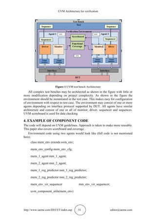
3. UVM TEST BENCH ARCHITECTURE
UVM libraries are huge set of classes, macros [12]. It is the first step for verification
engineer to select proper classes for his/her verification components development
[13]. Once selected proper classes, verification engineer need to implement those
components as per the requirement.
Fig. 1 shows UVM testbench Architecture components and suggests UVM classes
to be used for the development of those components.](https://image.slidesharecdn.com/ijecet0703004-160729092128/85/UVM-ARCHITECTURE-FOR-VERIFICATION-2-320.jpg)

![UVM Architecture for verification
http://www.iaeme.com/IJECET/index.asp 37 editor@iaeme.com
REFERENCES
[1] Universal Verification Methodology (UVM) 1.1 User guide by accellera
[2] Michael Smith, “Application Specific Integrated Circuits” Pearson Education
Asia
[3] Universal Verification Methodolog (UVM) 1.2 Class by accellera
[4] Rich Edelman Mentor Graphics Fremont, CA Shashi Bhutada Mentor Graphics,
Los Angeles, CA“An approach to automating UVM testbench writing”.
[5] H. Foster. Redefining Verification Performance (part 2), August 2010
[6] e Reusable Methodology, Cadence
[7] Incisive Enterprise Specman Products, Verification automation from block to
chip to system levels, Cadence
[8] OVM-SC Library Reference Version 2.0.1, February, 2009., Cadence Design
Systems, Inc
[9] VMM user guide, Synopsys, Inc
[10] SystemVerilog 3.1a Language Reference Manual, Accellera’s Extensions to
Verilog
[11] J. Bergeron. Writing Testbenches: Functional Verification of HDL models.
Kluwer Academic Publishers,
[12] A. Erickson. Are OVM & UVM Macros Evil? A Cost-Benefit Analysis. In
Proceeding of Design and Verification Conference (DVCON) , Mar. 2011
[13] Vijayakumar Suvvari and M.V.H. Bhaskara Murthy, VLSI Implementation of
Huffman Decoder Using Binary Tree Algorithm, International Journal of
Electronics and Communication Engineering & Technology, 4(6), 2013, pp. 85–
92.
[14] Mr. Nitin S. Sonar and Dr. R.R. Mudholkar, Implementation of Data Error
Corrector Using VLSI Technique, International Journal of Electronics and
Communication Engineering & Technology, 5(5), 2014, pp. 91–95
[15] Advanced UVM in the real world, Mark Litterick Jason Sprott Jonathan Bromley](https://image.slidesharecdn.com/ijecet0703004-160729092128/85/UVM-ARCHITECTURE-FOR-VERIFICATION-9-320.jpg)

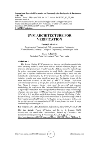
The document presents the Universal Verification Methodology (UVM) as a powerful method for verifying ASIC and FPGA designs, emphasizing its capacity for reuse and enhanced productivity in verification cycles. It outlines the architecture of a UVM testbench and highlights the importance of functional coverage in the verification process, providing examples of UVM design and test cases. The authors stress that while UVM is complex, it allows for significant improvements in verification efficiency if properly utilized.