Download as PDF, PPTX
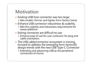
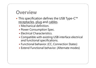
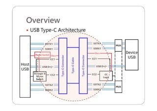
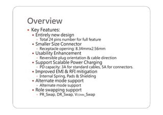
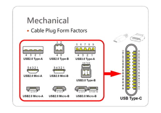
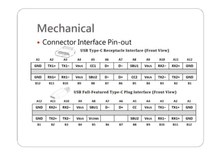
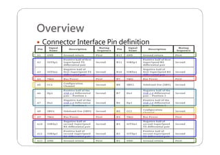
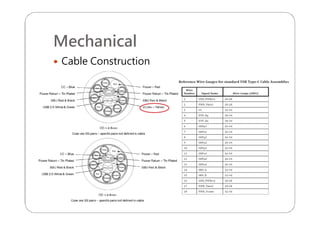
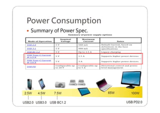
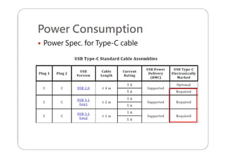
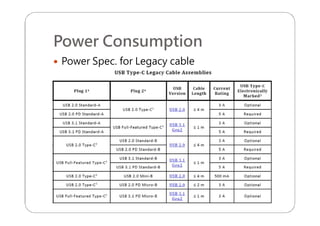
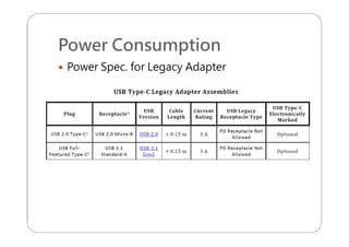
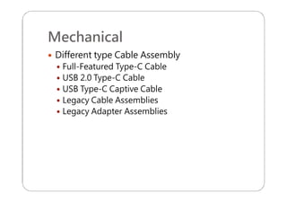
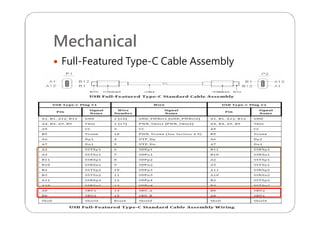
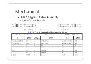
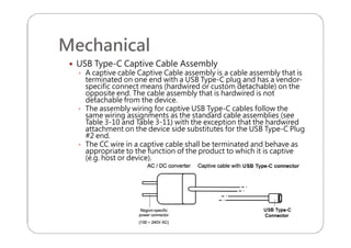
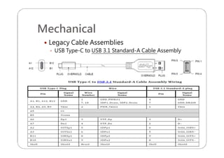
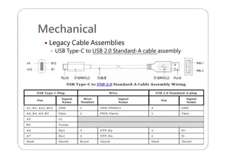
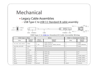
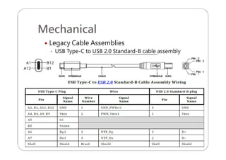
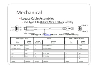
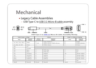
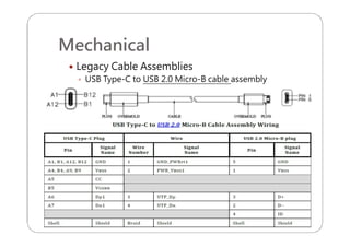
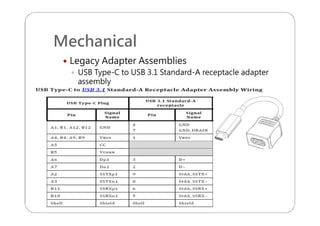
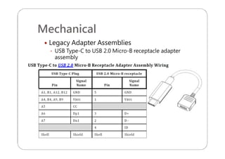
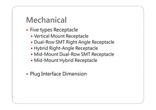
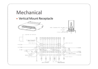
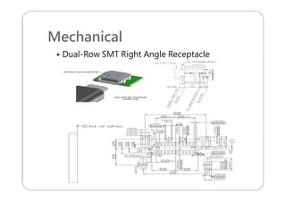
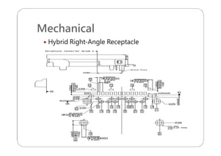
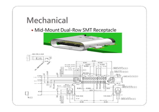
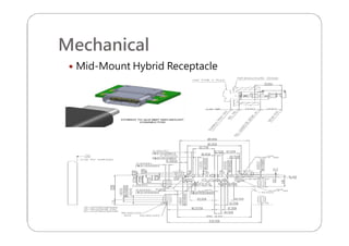
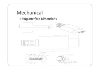
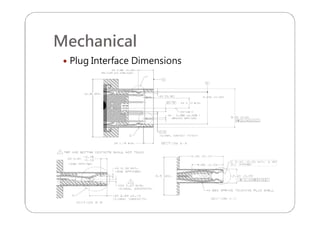
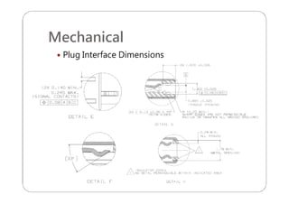
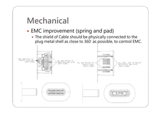
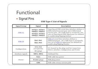
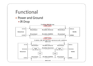
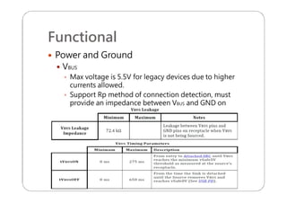
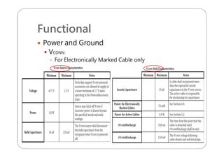
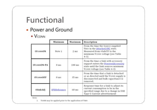
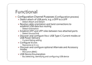
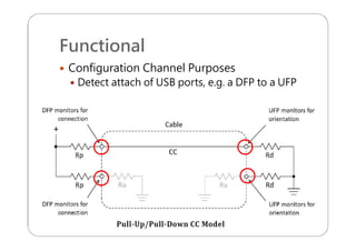
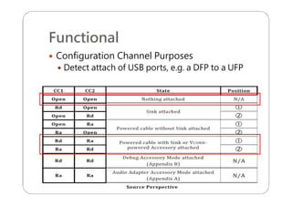
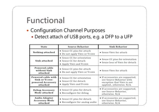
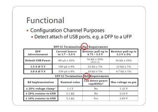
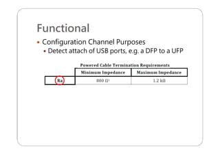
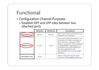
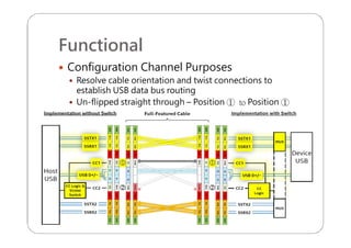
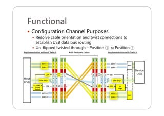
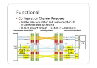
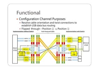
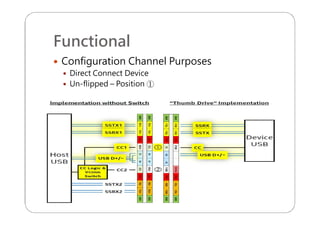
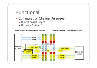
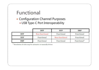
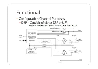
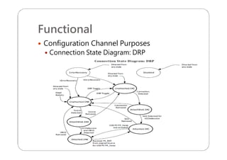
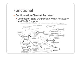
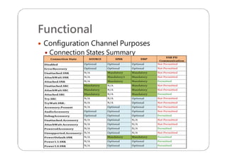
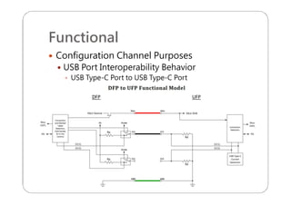
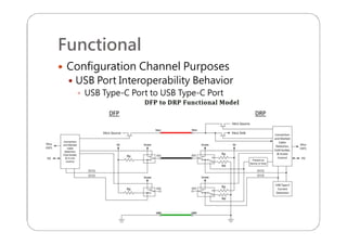
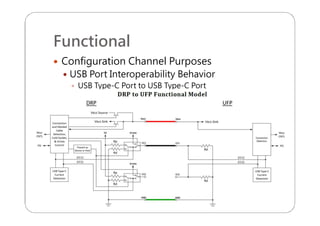
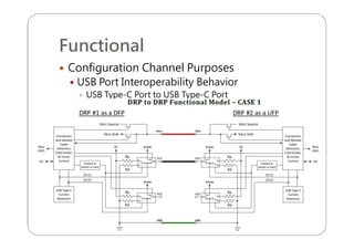
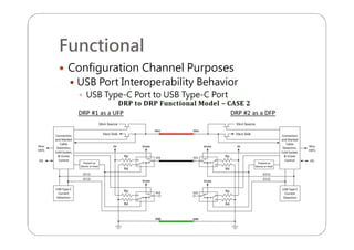
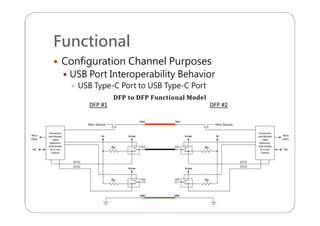
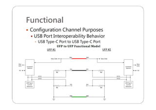
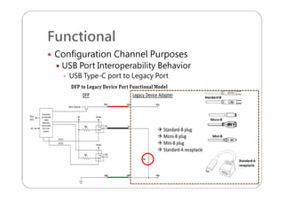
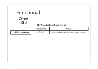
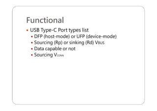
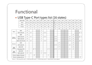
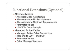
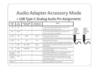
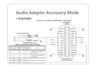
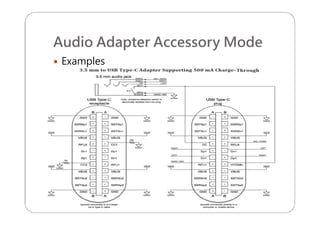


This document provides an overview and specifications for USB Type-C connectors and cables. It discusses the motivation for USB Type-C including making connectors smaller, more robust, and easier to use. The document then covers mechanical specifications for plugs, receptacles, and cable assemblies. It also discusses electrical characteristics, functional behaviors like configuration channel purposes and connection states, and extensions like alternate modes and audio adapter access.