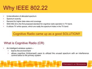
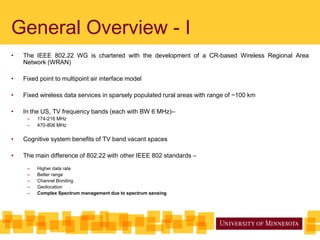
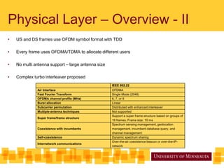
EE 5505
Wireless Communications


IEEE 802.22
   TV White Spaces


                     Presented by:
                      By:-
                     Nasim Yayhasoltani
                      Nasim
                     Akshay Soni
                      Yayhasoltani
                      Akshay Soni
Why IEEE 802.22
•    Underutilization of allocated spectrum
•    Spectrum scarcity
•    Demand for higher data rates and coverage
•    IEEE 802.22 is the first proposed standard for cognitive radio operation in TV band.
•    It utilizes TV white spaces, which are really the spectrum holes in the TV band


             Cognitive Radio came up as a good SOLUTION!!


    What is Cognitive Radio (CR)
•    An Intelligent wireless system –
      • learns the environment
      • allows cognitive (Unlicensed) users to utilized the unused spectrum with an interference
          control basis to the primary system
General Overview - I
•   The IEEE 802.22 WG is chartered with the development of a CR-based Wireless Regional Area
    Network (WRAN)

•   Fixed point to multipoint air interface model

•   Fixed wireless data services in sparsely populated rural areas with range of ~100 km

•   In the US, TV frequency bands (each with BW 6 MHz)–
     –   174-216 MHz
     –   470-806 MHz

•   Cognitive system benefits of TV band vacant spaces

•   The main difference of 802.22 with other IEEE 802 standards –
     –   Higher data rate
     –   Better range
     –   Channel Bonding
     –   Geolocation
     –   Complex Spectrum management due to spectrum sensing
General Overview - II
Spectrum Sensing
•   Most Important part of the overall 802.22 scheme
•   Base Station (BS) –
     –    Instructs CPEs to do sensing
     –    Tell CPEs when to do sensing
     –    Where to do sensing
     –    Analyze the sensing results
•   In TV white spaces, sensing is done for three different transmissions:
      –    Analog television:       Vacate at power level of -94 dBm
      –    Digital television:     Vacate at power level of -116 dBm
      –    Wireless microphones: Vacate at power level of -107 dBm


                           Parameter                Value for Wireless Microphone   Value for TV Broadcasting
                 Channel Availability Check Time                30 sec                        30 sec
                      Non-Occupancy Period                    10 minutes                    10 minutes
                     Channel Detection Time                      2sec                           sec
                       Channel Setup Time                        2 sec                         2 sec
                 Channel Opening Transmission
                                                               100 msec                     100 msec
               Time(Aggregate transmission time)
                  Channel Move Time(In-service
                                                                 2 sec                        2 sec
                           monitoring)
               Channel Closing Transmission Time
                                                               100 msec                     100 msec
                    (Aggregate transmission)
                Interference Detection Threshold               -107 dBm                     -116 dBm
Channel Bonding
•    Beneficial to use wider bandwidth system


•    Using just one TV channel –
      –   Cannot meet the required data rates


•    The current US grade-A TV allocation restricts adjacent allocated TV channels to have at
     least 2 empty channels between them.


    Geolocation
•    Devices should be in fixed position and BS needs to know location information of all the
     CPEs.

•    The location of the BS must be known to within a 15 m radius while the location of CPE
     must be known to within a 100 m radius.
Physical Layer – Overview - I
•   Channel with excessive multipath delay
     –   Largest delay of > 60 µs
     –   Average delay of 35 µs


•   Use VHF/UHF TV bands – 54 to 862 MHz

•   Robust OFDMA is proposed with
     –   Long symbol time
     –   Long CP


•   Different users can have different channel conditions
     –   Flexibility is inherent in this standard
     –   Adaptive modulation and coding
           •   Three modulation schemes (QPSK, 16 QAM and 64 QAM)
           •   Four coding rates (1/2, 2/3, 3/4, and 5/6)
     –   Four different lengths of CP (1/4, 1/8, 1/16 and 1/32)
Physical Layer – Overview - II
•   US and DS frames use OFDM symbol format with TDD

•   Every frame uses OFDMA/TDMA to allocate different users

•   No multi antenna support – large antenna size

•   Complex turbo interleaver proposed
                                                    IEEE 802.22
              Air Interface                         OFDMA
              Fast Fourier Transform                Single Mode (2048)
              OFDMA channel profile (MHz)           6, 7, or 8
              Burst allocation                      Linear
              Subcarrier permutation                Distributed with enhanced interleaver
              Multiple-antenna techniques           Not supported
                                                    Support a super frame structure based on groups of
              Super frame/frame structure
                                                    16 frames. Frame size: 10 ms
                                                    Spectrum sensing management, geolocation
              Coexistence with incumbents           management, incumbent database query, and
                                                    channel management.
              Self-coexistence                      Dynamic spectrum sharing
                                                    Over-the-air coexistence beacon or over-the-IP-
              Internetwork communications
                                                    network
Physical Layer – Frame Structure
•   Superframe consists of 16 frames of 10 ms each

•   Each frame with its own CP, header and bursts

•   Superframe control header and preamble only on first frame
Physical Layer – Pilot Pattern
•   Repeated in every 7 OFDM symbols and 7 subcarriers

•   Best performance for edge user on every sub-carrier after waiting for 7 symbols

•   Robust channel estimation using 7 OFDM symbols
                                        OFDMA symbol
                           Subcarrier


                                                                      Pilot Subcarrier


                                                                      Data Subcarrier
Physical Layer – Design Parameters
•   Based on TDD-OFDMA

•   Subcarriers classified as data subcarriers, pilot subcarriers, guard and DC subcarriers


              TV channel bandwidth (MHz)                   6                   7       8

              Total number of subcarriers, NFFT            2048

              Number of guard subcarriers, NG (L, DC, R)   368 (184, 1, 183)

              Number of used subcarriers, NT = ND + NP     1680

              Number of data subcarriers, ND               1440

              Number of pilot subcarriers, NP              240

              Subcarrier spacing, F (Hz)                   3.348               3.906   4.464

              Occupied bandwidth (MHz)                     5.625               6.566   7.504
Physical Layer – Block Diagram
Comparison – WRAN & WiMax
                                               IEEE 802.22                                   WiMax

           PHY Profile                            OFDMA                                      OFDMA

            FFT Mode                                2048                                       512

    Sampling Frequency (MHz)                         6.9                                       5.6

     Subcarrier Spacing (KHz)                        3.3                                       10.9

  Useful Symbol Time (1/f) (µsec)                  298.7                                       91.4

     Maximum CP time (µsec)                         74.7                                       11.4

     Peak Data Rates (Mbps)                         22.7                                       15.8

         Burst Allocation                          Linear                                Two dimensional

     Subcarrier Permutation         Distributed with enhanced interleaver             Adjacent or distributed

   Multiple Antenna Techniques                 Not supported                Supports multiplexing, STC and beamforming
Thank You !!

IEEE 802.22 WRAN Standard

  • 1.
    EE 5505 Wireless Communications IEEE802.22 TV White Spaces Presented by: By:- Nasim Yayhasoltani Nasim Akshay Soni Yayhasoltani Akshay Soni
  • 2.
    Why IEEE 802.22 • Underutilization of allocated spectrum • Spectrum scarcity • Demand for higher data rates and coverage • IEEE 802.22 is the first proposed standard for cognitive radio operation in TV band. • It utilizes TV white spaces, which are really the spectrum holes in the TV band Cognitive Radio came up as a good SOLUTION!! What is Cognitive Radio (CR) • An Intelligent wireless system – • learns the environment • allows cognitive (Unlicensed) users to utilized the unused spectrum with an interference control basis to the primary system
  • 3.
    General Overview -I • The IEEE 802.22 WG is chartered with the development of a CR-based Wireless Regional Area Network (WRAN) • Fixed point to multipoint air interface model • Fixed wireless data services in sparsely populated rural areas with range of ~100 km • In the US, TV frequency bands (each with BW 6 MHz)– – 174-216 MHz – 470-806 MHz • Cognitive system benefits of TV band vacant spaces • The main difference of 802.22 with other IEEE 802 standards – – Higher data rate – Better range – Channel Bonding – Geolocation – Complex Spectrum management due to spectrum sensing
  • 4.
  • 5.
    Spectrum Sensing • Most Important part of the overall 802.22 scheme • Base Station (BS) – – Instructs CPEs to do sensing – Tell CPEs when to do sensing – Where to do sensing – Analyze the sensing results • In TV white spaces, sensing is done for three different transmissions: – Analog television: Vacate at power level of -94 dBm – Digital television: Vacate at power level of -116 dBm – Wireless microphones: Vacate at power level of -107 dBm Parameter Value for Wireless Microphone Value for TV Broadcasting Channel Availability Check Time 30 sec 30 sec Non-Occupancy Period 10 minutes 10 minutes Channel Detection Time 2sec sec Channel Setup Time 2 sec 2 sec Channel Opening Transmission 100 msec 100 msec Time(Aggregate transmission time) Channel Move Time(In-service 2 sec 2 sec monitoring) Channel Closing Transmission Time 100 msec 100 msec (Aggregate transmission) Interference Detection Threshold -107 dBm -116 dBm
  • 6.
    Channel Bonding • Beneficial to use wider bandwidth system • Using just one TV channel – – Cannot meet the required data rates • The current US grade-A TV allocation restricts adjacent allocated TV channels to have at least 2 empty channels between them. Geolocation • Devices should be in fixed position and BS needs to know location information of all the CPEs. • The location of the BS must be known to within a 15 m radius while the location of CPE must be known to within a 100 m radius.
  • 7.
    Physical Layer –Overview - I • Channel with excessive multipath delay – Largest delay of > 60 µs – Average delay of 35 µs • Use VHF/UHF TV bands – 54 to 862 MHz • Robust OFDMA is proposed with – Long symbol time – Long CP • Different users can have different channel conditions – Flexibility is inherent in this standard – Adaptive modulation and coding • Three modulation schemes (QPSK, 16 QAM and 64 QAM) • Four coding rates (1/2, 2/3, 3/4, and 5/6) – Four different lengths of CP (1/4, 1/8, 1/16 and 1/32)
  • 8.
    Physical Layer –Overview - II • US and DS frames use OFDM symbol format with TDD • Every frame uses OFDMA/TDMA to allocate different users • No multi antenna support – large antenna size • Complex turbo interleaver proposed IEEE 802.22 Air Interface OFDMA Fast Fourier Transform Single Mode (2048) OFDMA channel profile (MHz) 6, 7, or 8 Burst allocation Linear Subcarrier permutation Distributed with enhanced interleaver Multiple-antenna techniques Not supported Support a super frame structure based on groups of Super frame/frame structure 16 frames. Frame size: 10 ms Spectrum sensing management, geolocation Coexistence with incumbents management, incumbent database query, and channel management. Self-coexistence Dynamic spectrum sharing Over-the-air coexistence beacon or over-the-IP- Internetwork communications network
  • 9.
    Physical Layer –Frame Structure • Superframe consists of 16 frames of 10 ms each • Each frame with its own CP, header and bursts • Superframe control header and preamble only on first frame
  • 10.
    Physical Layer –Pilot Pattern • Repeated in every 7 OFDM symbols and 7 subcarriers • Best performance for edge user on every sub-carrier after waiting for 7 symbols • Robust channel estimation using 7 OFDM symbols OFDMA symbol Subcarrier Pilot Subcarrier Data Subcarrier
  • 11.
    Physical Layer –Design Parameters • Based on TDD-OFDMA • Subcarriers classified as data subcarriers, pilot subcarriers, guard and DC subcarriers TV channel bandwidth (MHz) 6 7 8 Total number of subcarriers, NFFT 2048 Number of guard subcarriers, NG (L, DC, R) 368 (184, 1, 183) Number of used subcarriers, NT = ND + NP 1680 Number of data subcarriers, ND 1440 Number of pilot subcarriers, NP 240 Subcarrier spacing, F (Hz) 3.348 3.906 4.464 Occupied bandwidth (MHz) 5.625 6.566 7.504
  • 12.
    Physical Layer –Block Diagram
  • 13.
    Comparison – WRAN& WiMax IEEE 802.22 WiMax PHY Profile OFDMA OFDMA FFT Mode 2048 512 Sampling Frequency (MHz) 6.9 5.6 Subcarrier Spacing (KHz) 3.3 10.9 Useful Symbol Time (1/f) (µsec) 298.7 91.4 Maximum CP time (µsec) 74.7 11.4 Peak Data Rates (Mbps) 22.7 15.8 Burst Allocation Linear Two dimensional Subcarrier Permutation Distributed with enhanced interleaver Adjacent or distributed Multiple Antenna Techniques Not supported Supports multiplexing, STC and beamforming
  • 14.