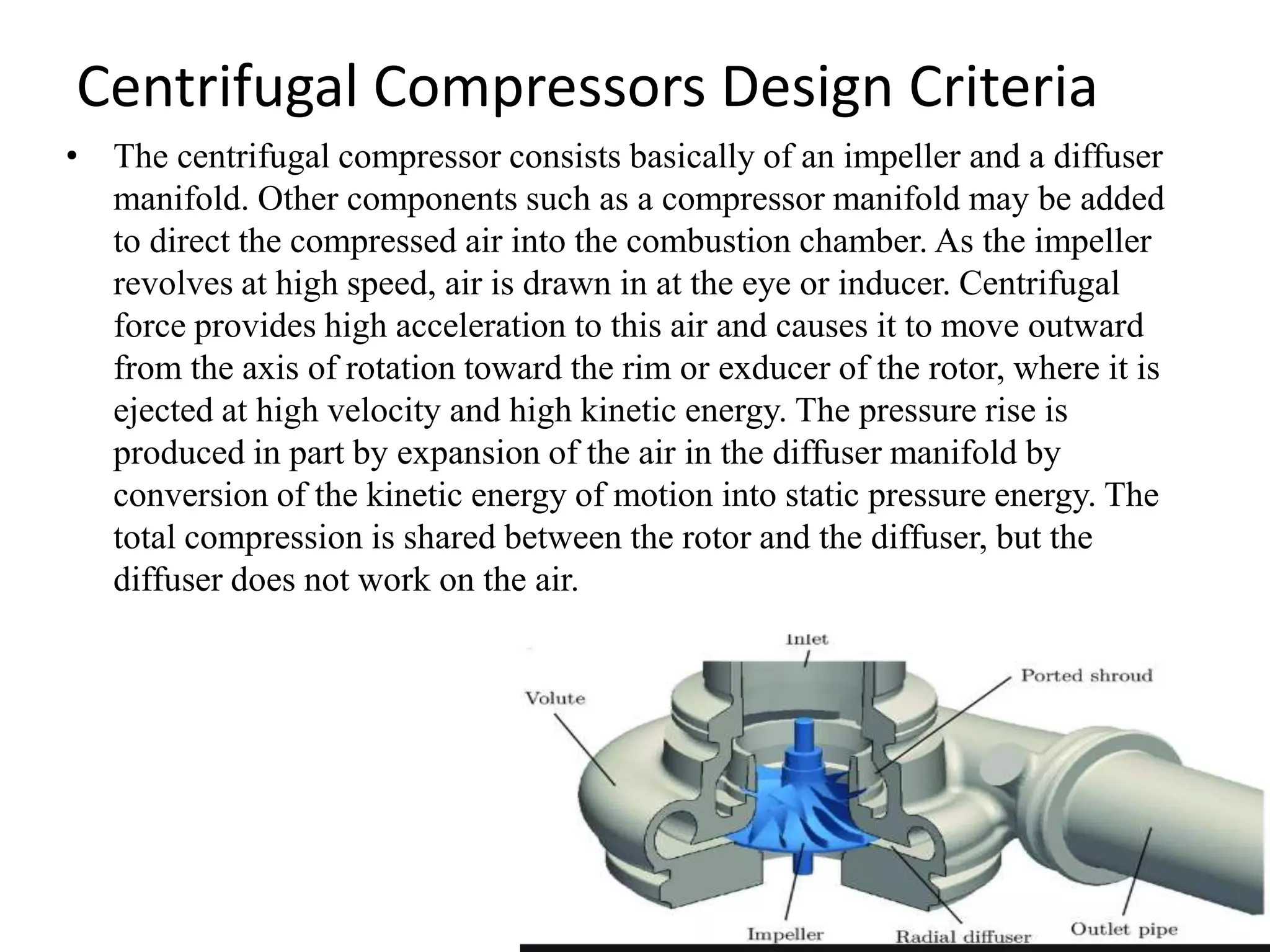
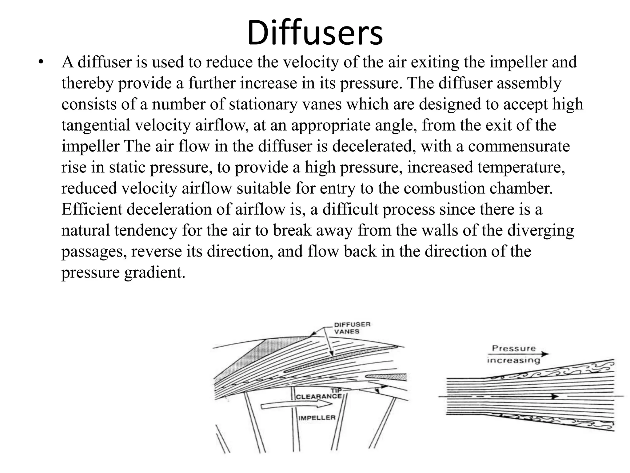
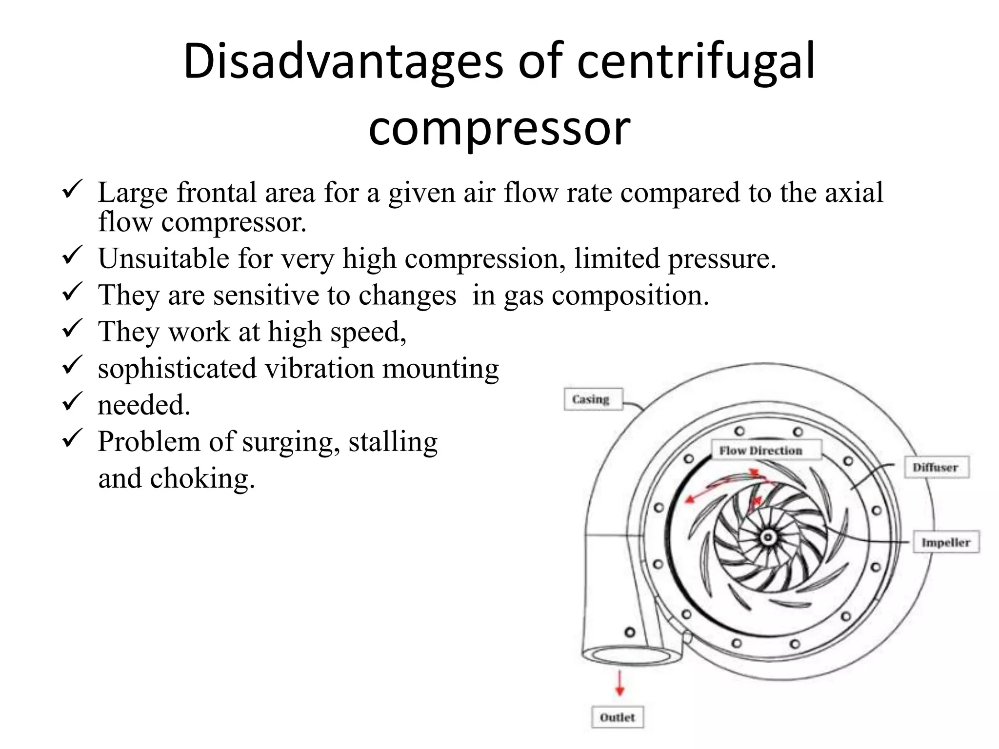
SlideShare a Scribd company logo
M3. Present the difference between
centrifugal and axial compressors,
their design criteria, usage, merits
and demits in application along with
proper examples.
Welcome
Centrifugal compressor
• The centrifugal compressor consists of an impeller which is rotated at high
speed by a turbine. This causes air to be induced into the centre of the
impeller and then accelerated radially outwards between the impeller vanes
creating a rise in static pressure. This high velocity air is then decelerated
through a number of fixed diverging passages, known as the diffuser, with a
further consequent rise in static pressure. In practice, it is usual to design
the compressor such that about 50% of the static pressure rise occurs in the
impeller and 50% in the diffuser.
Axial compressor
• Compressed gas principally flows parallel to the rotation axis. Axial compressors
have the benefits of high efficiency and large flow rates, particularly in relation to
their sizes and cross sections. They offer the most compact and lightweight
compressor design for large volumes and the lowest cost per flow rate for large flow
rate applications. They do require several rows of blades (axial stages) to achieve
large pressure rises, making them complex and fragile relative to other compressor
designs such as centrifugal compressors.
Axial Compressors Design Criteria
• The axial-flow compressor is made up of a series of rotating airfoils called
rotor blades and a stationary set of airfoil called stator vanes. As its name
implies, the air is being compressed in a direction parallel to the axis of the
engine. A row of rotating and stationary blades is called a stage. The entire
compressor is made up of a series of alternating rotor and stator vane
stages, with each stage constructed of blades shaped to provide the most lift
for the least drag.
Centrifugal Compressors Design Criteria
• The centrifugal compressor consists basically of an impeller and a diffuser
manifold. Other components such as a compressor manifold may be added
to direct the compressed air into the combustion chamber. As the impeller
revolves at high speed, air is drawn in at the eye or inducer. Centrifugal
force provides high acceleration to this air and causes it to move outward
from the axis of rotation toward the rim or exducer of the rotor, where it is
ejected at high velocity and high kinetic energy. The pressure rise is
produced in part by expansion of the air in the diffuser manifold by
conversion of the kinetic energy of motion into static pressure energy. The
total compression is shared between the rotor and the diffuser, but the
diffuser does not work on the air.
• Impellers: In order to maximize the airflow and pressure rise through the
compressor, impellers are normally designed to operate at tip speeds
approaching 600m/s. The local air temperature and component stresses
associated with such operation require the impeller to be manufactured
from high strength, aluminum, titanium or steel alloys. In the centre inlet,
or eye, region of the impeller the vanes are curved in the direction of
rotation to ease the flow of air into the compressor. The flow passages in
the impeller and diffuser must be carefully designed to take account of the
changing pressure, temperature, density and velocities of the air as it passes
through them. The shape of the impeller channels between eye and tip is
designed to obtain a uniform change in velocity thereby avoiding local
decelerations up the trailing face of the vane which might lead to flow
separation.
Diffusers
• A diffuser is used to reduce the velocity of the air exiting the impeller and
thereby provide a further increase in its pressure. The diffuser assembly
consists of a number of stationary vanes which are designed to accept high
tangential velocity airflow, at an appropriate angle, from the exit of the
impeller The air flow in the diffuser is decelerated, with a commensurate
rise in static pressure, to provide a high pressure, increased temperature,
reduced velocity airflow suitable for entry to the combustion chamber.
Efficient deceleration of airflow is, a difficult process since there is a
natural tendency for the air to break away from the walls of the diverging
passages, reverse its direction, and flow back in the direction of the
pressure gradient.
Centrifugal Compressor Usage
With the development of aero engines, axial compressors have nearly replaced
centrifugal compressors. Thus, centrifugal compressors are found in small
turbofan engines. Centrifugal compressors are used in many industrial
applications such as refineries, chemical and petrochemical plants, natural
gas processing and transmission plants, very large-scale refrigeration, and
iron and steel mills. These centrifugal compressors may have single or
multiple stages (up to five stages) and can operate at very high inlet
pressures. Rolls-Royce RFA36 and RFA24 giant compressors may have
pressures up to 155 bar and flow rate of 200 m3/min at design speed from
3,600 to 12,800 rpm.
Axial Compressor Usages
The most frequent application is in aircraft turbojet engines, nearly 100% of
them use an axial flow compressor to compress the air going through the
engine, resulting in higher pressure air entering the combustion area where
fuel is injected and burned, creating energy via the hot airflow through the
turbine stages, which are used to power the compressor stages, and then out
the back as thrust. Axial compressors are used in applications where high
mass flow rates are required. Axial compressors are exclusively used in jet
engines of higher thrust. Also in land based gas turbines used for power
generation. A few facilities in the world have axial compressors to generate
high mach number flow for continuous wind tunnel testing.
Advantages of Axial Flow Compressor:
i. High peak efficiency.
ii. Small frontal area for given flow.
iii. Straight through flow, allowing high ram efficiency.
iv. Increased pressure rise due to increased number of
stages with negligible losses.
Disadvantages of Axial Flow Compressor:
i. Good efficiency over narrow rotational speed range.
ii. Manufacturing is difficult.
iii. Cost is very high.
iv. Heavy weight.
v. High starting power requirements.
Advantages of centrifugal compressor
 Centrifugal compressors are reliable, low maintenance.
 Generating a higher pressure ratio per stage as compared to axial flow
compressor.
 Low weight, easy to design and manufacture.
 Suitable for continuous compressed air supply, such as cooling unit.
 High-flow rate than the positive displacement
 The oil free in nature.
 They have fewer rubbing parts compressor.
 Relatively energy efficient.
 Wide range of rotational speed.
 It does not require special foundation.
Disadvantages of centrifugal
compressor
 Large frontal area for a given air flow rate compared to the axial
flow compressor.
 Unsuitable for very high compression, limited pressure.
 They are sensitive to changes in gas composition.
 They work at high speed,
 sophisticated vibration mounting
 needed.
 Problem of surging, stalling
and choking.
Thanks you

More Related Content

What's hot

Centrifugal compressor
Centrifugal compressor Centrifugal compressor
Centrifugal compressor
Héctor Nguema Ondo
 
Centrifugal Compressor
Centrifugal CompressorCentrifugal Compressor
Centrifugal Compressor
Ankit Singh
 
Degree of reaction
Degree of reactionDegree of reaction
Degree of reaction
Harshit Jain
 
Classification of steam Turbine
Classification of steam TurbineClassification of steam Turbine
Classification of steam Turbine
Showhanur Rahman
 
Gas Turbine and Jet propulsion
Gas Turbine and Jet propulsionGas Turbine and Jet propulsion
Gas Turbine and Jet propulsionSLA1987
 
Axial flow compressor
Axial flow compressor Axial flow compressor
Axial flow compressor
Rupesh Kumar
 
Compressors and its applications
Compressors and its applicationsCompressors and its applications
Compressors and its applications
Taha Malampatti
 
A presentation On Epicycle Gear Train
A presentation On Epicycle Gear TrainA presentation On Epicycle Gear Train
A presentation On Epicycle Gear Train
Manthan Thakkar
 
Basics of Compressor
Basics of CompressorBasics of Compressor
Basics of CompressorSLA1987
 
hydraulic and pneumatic Valves
hydraulic and pneumatic Valveshydraulic and pneumatic Valves
hydraulic and pneumatic Valves
Sam Aero
 
Vortex tube _steam_jet_refrigeration
Vortex tube _steam_jet_refrigerationVortex tube _steam_jet_refrigeration
Vortex tube _steam_jet_refrigeration
RADJARAM BALIN
 
reciprocating compressor
reciprocating compressorreciprocating compressor
reciprocating compressor
Rajesh Sharma
 
Hydraulic systems
Hydraulic  systemsHydraulic  systems
Hydraulic systems
Thulasikanth Vaddi
 
TYPES OF COMPRESSORS
TYPES OF COMPRESSORSTYPES OF COMPRESSORS
TYPES OF COMPRESSORS
Sriram Venkatesh
 
types of expansion devices in rac
types of expansion devices in ractypes of expansion devices in rac
types of expansion devices in racAnasuya Barik
 
Gas turbines
Gas turbines Gas turbines
Gas turbines
krishna khot
 
Gas Turbine PPT
Gas Turbine PPTGas Turbine PPT
Gas Turbine PPT
A M
 
Gas turbine and its classification
Gas turbine and its classificationGas turbine and its classification
Gas turbine and its classification
Md. Faisal Ahemed Rony
 
Jet propulsion
Jet propulsionJet propulsion
Jet propulsion
SANDIP THORAT
 

What's hot (20)

Centrifugal compressor
Centrifugal compressor Centrifugal compressor
Centrifugal compressor
 
Centrifugal Compressor
Centrifugal CompressorCentrifugal Compressor
Centrifugal Compressor
 
Degree of reaction
Degree of reactionDegree of reaction
Degree of reaction
 
Classification of steam Turbine
Classification of steam TurbineClassification of steam Turbine
Classification of steam Turbine
 
Gas Turbine and Jet propulsion
Gas Turbine and Jet propulsionGas Turbine and Jet propulsion
Gas Turbine and Jet propulsion
 
Axial flow compressor
Axial flow compressor Axial flow compressor
Axial flow compressor
 
Compressors and its applications
Compressors and its applicationsCompressors and its applications
Compressors and its applications
 
A presentation On Epicycle Gear Train
A presentation On Epicycle Gear TrainA presentation On Epicycle Gear Train
A presentation On Epicycle Gear Train
 
Basics of Compressor
Basics of CompressorBasics of Compressor
Basics of Compressor
 
hydraulic and pneumatic Valves
hydraulic and pneumatic Valveshydraulic and pneumatic Valves
hydraulic and pneumatic Valves
 
Compressor
CompressorCompressor
Compressor
 
Vortex tube _steam_jet_refrigeration
Vortex tube _steam_jet_refrigerationVortex tube _steam_jet_refrigeration
Vortex tube _steam_jet_refrigeration
 
reciprocating compressor
reciprocating compressorreciprocating compressor
reciprocating compressor
 
Hydraulic systems
Hydraulic  systemsHydraulic  systems
Hydraulic systems
 
TYPES OF COMPRESSORS
TYPES OF COMPRESSORSTYPES OF COMPRESSORS
TYPES OF COMPRESSORS
 
types of expansion devices in rac
types of expansion devices in ractypes of expansion devices in rac
types of expansion devices in rac
 
Gas turbines
Gas turbines Gas turbines
Gas turbines
 
Gas Turbine PPT
Gas Turbine PPTGas Turbine PPT
Gas Turbine PPT
 
Gas turbine and its classification
Gas turbine and its classificationGas turbine and its classification
Gas turbine and its classification
 
Jet propulsion
Jet propulsionJet propulsion
Jet propulsion
 

Similar to Comparison Centrifugal and axial compessor

Air Compressors
Air CompressorsAir Compressors
Air Compressors
Keyur Vadodariya
 
Air compresser by Ravi Gelani
Air compresser by Ravi GelaniAir compresser by Ravi Gelani
Air compresser by Ravi Gelani
Ravi Gelani
 
Lecture-1- Compressor and its Types.ppt
Lecture-1- Compressor and its Types.pptLecture-1- Compressor and its Types.ppt
Lecture-1- Compressor and its Types.ppt
WaqasRahman10
 
Compressors system Designing 919825024651
Compressors system Designing 919825024651Compressors system Designing 919825024651
Compressors system Designing 919825024651
Sdsplit Split
 
Compressor final
Compressor finalCompressor final
Compressor final
Er.Nishant Pathak
 
Compressed Air Network
Compressed Air NetworkCompressed Air Network
Compressed Air Network
Rohan Dusane
 
chapter-no-3-air-compressors (1).ppt
chapter-no-3-air-compressors (1).pptchapter-no-3-air-compressors (1).ppt
chapter-no-3-air-compressors (1).ppt
ArchanaMaske2
 
Radial compressor.pptx mm
Radial compressor.pptx mmRadial compressor.pptx mm
Radial compressor.pptx mm
Ajay Dua
 
chapter-no-3-air-compressors.ppt
chapter-no-3-air-compressors.pptchapter-no-3-air-compressors.ppt
chapter-no-3-air-compressors.ppt
BeselamuGodebo
 
chapter-no-3-air-compressors.ppt
chapter-no-3-air-compressors.pptchapter-no-3-air-compressors.ppt
chapter-no-3-air-compressors.ppt
zerihunsamuel1
 
chapter-no-3-air-compressors.ppt
chapter-no-3-air-compressors.pptchapter-no-3-air-compressors.ppt
chapter-no-3-air-compressors.ppt
DramilThakkar2
 
chapter-no-3-air-compressors.ppt for electric
chapter-no-3-air-compressors.ppt for electricchapter-no-3-air-compressors.ppt for electric
chapter-no-3-air-compressors.ppt for electric
basant11731
 
K12105 shahrukh
K12105 shahrukhK12105 shahrukh
K12105 shahrukh
Shivam Kumar
 
compressors types
compressors typescompressors types
compressors types
Engr Farhan Masood
 
Compressor Classifications.pdf
Compressor Classifications.pdfCompressor Classifications.pdf
Compressor Classifications.pdf
KAhmedRehman
 
Compressor and Types
Compressor and TypesCompressor and Types
Compressor and Types
Muhammad Usama
 
chaptrno-140114211033-phpapp02.pptx
chaptrno-140114211033-phpapp02.pptxchaptrno-140114211033-phpapp02.pptx
chaptrno-140114211033-phpapp02.pptx
prabhakarjha82
 
Compressor
CompressorCompressor
Compressor
Zillur Rahman ZR
 
Energy conversion devices 05
Energy conversion devices  05Energy conversion devices  05
Energy conversion devices 05
Carnegie Mellon University
 

Similar to Comparison Centrifugal and axial compessor (20)

Air Compressors
Air CompressorsAir Compressors
Air Compressors
 
Air compresser by Ravi Gelani
Air compresser by Ravi GelaniAir compresser by Ravi Gelani
Air compresser by Ravi Gelani
 
Lecture-1- Compressor and its Types.ppt
Lecture-1- Compressor and its Types.pptLecture-1- Compressor and its Types.ppt
Lecture-1- Compressor and its Types.ppt
 
Compressors system Designing 919825024651
Compressors system Designing 919825024651Compressors system Designing 919825024651
Compressors system Designing 919825024651
 
Compressor final
Compressor finalCompressor final
Compressor final
 
Compressor final
Compressor finalCompressor final
Compressor final
 
Compressed Air Network
Compressed Air NetworkCompressed Air Network
Compressed Air Network
 
chapter-no-3-air-compressors (1).ppt
chapter-no-3-air-compressors (1).pptchapter-no-3-air-compressors (1).ppt
chapter-no-3-air-compressors (1).ppt
 
Radial compressor.pptx mm
Radial compressor.pptx mmRadial compressor.pptx mm
Radial compressor.pptx mm
 
chapter-no-3-air-compressors.ppt
chapter-no-3-air-compressors.pptchapter-no-3-air-compressors.ppt
chapter-no-3-air-compressors.ppt
 
chapter-no-3-air-compressors.ppt
chapter-no-3-air-compressors.pptchapter-no-3-air-compressors.ppt
chapter-no-3-air-compressors.ppt
 
chapter-no-3-air-compressors.ppt
chapter-no-3-air-compressors.pptchapter-no-3-air-compressors.ppt
chapter-no-3-air-compressors.ppt
 
chapter-no-3-air-compressors.ppt for electric
chapter-no-3-air-compressors.ppt for electricchapter-no-3-air-compressors.ppt for electric
chapter-no-3-air-compressors.ppt for electric
 
K12105 shahrukh
K12105 shahrukhK12105 shahrukh
K12105 shahrukh
 
compressors types
compressors typescompressors types
compressors types
 
Compressor Classifications.pdf
Compressor Classifications.pdfCompressor Classifications.pdf
Compressor Classifications.pdf
 
Compressor and Types
Compressor and TypesCompressor and Types
Compressor and Types
 
chaptrno-140114211033-phpapp02.pptx
chaptrno-140114211033-phpapp02.pptxchaptrno-140114211033-phpapp02.pptx
chaptrno-140114211033-phpapp02.pptx
 
Compressor
CompressorCompressor
Compressor
 
Energy conversion devices 05
Energy conversion devices  05Energy conversion devices  05
Energy conversion devices 05
 

Recently uploaded

Railway Signalling Principles Edition 3.pdf
Railway Signalling Principles Edition 3.pdfRailway Signalling Principles Edition 3.pdf
Railway Signalling Principles Edition 3.pdf
TeeVichai
 
Pile Foundation by Venkatesh Taduvai (Sub Geotechnical Engineering II)-conver...
Pile Foundation by Venkatesh Taduvai (Sub Geotechnical Engineering II)-conver...Pile Foundation by Venkatesh Taduvai (Sub Geotechnical Engineering II)-conver...
Pile Foundation by Venkatesh Taduvai (Sub Geotechnical Engineering II)-conver...
AJAYKUMARPUND1
 
power quality voltage fluctuation UNIT - I.pptx
power quality voltage fluctuation UNIT - I.pptxpower quality voltage fluctuation UNIT - I.pptx
power quality voltage fluctuation UNIT - I.pptx
ViniHema
 
The role of big data in decision making.
The role of big data in decision making.The role of big data in decision making.
The role of big data in decision making.
ankuprajapati0525
 
DESIGN A COTTON SEED SEPARATION MACHINE.docx
DESIGN A COTTON SEED SEPARATION MACHINE.docxDESIGN A COTTON SEED SEPARATION MACHINE.docx
DESIGN A COTTON SEED SEPARATION MACHINE.docx
FluxPrime1
 
MCQ Soil mechanics questions (Soil shear strength).pdf
MCQ Soil mechanics questions (Soil shear strength).pdfMCQ Soil mechanics questions (Soil shear strength).pdf
MCQ Soil mechanics questions (Soil shear strength).pdf
Osamah Alsalih
 
Forklift Classes Overview by Intella Parts
Forklift Classes Overview by Intella PartsForklift Classes Overview by Intella Parts
Forklift Classes Overview by Intella Parts
Intella Parts
 
LIGA(E)11111111111111111111111111111111111111111.ppt
LIGA(E)11111111111111111111111111111111111111111.pptLIGA(E)11111111111111111111111111111111111111111.ppt
LIGA(E)11111111111111111111111111111111111111111.ppt
ssuser9bd3ba
 
Immunizing Image Classifiers Against Localized Adversary Attacks
Immunizing Image Classifiers Against Localized Adversary AttacksImmunizing Image Classifiers Against Localized Adversary Attacks
Immunizing Image Classifiers Against Localized Adversary Attacks
gerogepatton
 
CME397 Surface Engineering- Professional Elective
CME397 Surface Engineering- Professional ElectiveCME397 Surface Engineering- Professional Elective
CME397 Surface Engineering- Professional Elective
karthi keyan
 
CFD Simulation of By-pass Flow in a HRSG module by R&R Consult.pptx
CFD Simulation of By-pass Flow in a HRSG module by R&R Consult.pptxCFD Simulation of By-pass Flow in a HRSG module by R&R Consult.pptx
CFD Simulation of By-pass Flow in a HRSG module by R&R Consult.pptx
R&R Consult
 
H.Seo, ICLR 2024, MLILAB, KAIST AI.pdf
H.Seo,  ICLR 2024, MLILAB,  KAIST AI.pdfH.Seo,  ICLR 2024, MLILAB,  KAIST AI.pdf
H.Seo, ICLR 2024, MLILAB, KAIST AI.pdf
MLILAB
 
road safety engineering r s e unit 3.pdf
road safety engineering  r s e unit 3.pdfroad safety engineering  r s e unit 3.pdf
road safety engineering r s e unit 3.pdf
VENKATESHvenky89705
 
Democratizing Fuzzing at Scale by Abhishek Arya
Democratizing Fuzzing at Scale by Abhishek AryaDemocratizing Fuzzing at Scale by Abhishek Arya
Democratizing Fuzzing at Scale by Abhishek Arya
abh.arya
 
block diagram and signal flow graph representation
block diagram and signal flow graph representationblock diagram and signal flow graph representation
block diagram and signal flow graph representation
Divya Somashekar
 
weather web application report.pdf
weather web application report.pdfweather web application report.pdf
weather web application report.pdf
Pratik Pawar
 
addressing modes in computer architecture
addressing modes  in computer architectureaddressing modes  in computer architecture
addressing modes in computer architecture
ShahidSultan24
 
Architectural Portfolio Sean Lockwood
Architectural Portfolio Sean LockwoodArchitectural Portfolio Sean Lockwood
Architectural Portfolio Sean Lockwood
seandesed
 
WATER CRISIS and its solutions-pptx 1234
WATER CRISIS and its solutions-pptx 1234WATER CRISIS and its solutions-pptx 1234
WATER CRISIS and its solutions-pptx 1234
AafreenAbuthahir2
 
The Benefits and Techniques of Trenchless Pipe Repair.pdf
The Benefits and Techniques of Trenchless Pipe Repair.pdfThe Benefits and Techniques of Trenchless Pipe Repair.pdf
The Benefits and Techniques of Trenchless Pipe Repair.pdf
Pipe Restoration Solutions
 

Recently uploaded (20)

Railway Signalling Principles Edition 3.pdf
Railway Signalling Principles Edition 3.pdfRailway Signalling Principles Edition 3.pdf
Railway Signalling Principles Edition 3.pdf
 
Pile Foundation by Venkatesh Taduvai (Sub Geotechnical Engineering II)-conver...
Pile Foundation by Venkatesh Taduvai (Sub Geotechnical Engineering II)-conver...Pile Foundation by Venkatesh Taduvai (Sub Geotechnical Engineering II)-conver...
Pile Foundation by Venkatesh Taduvai (Sub Geotechnical Engineering II)-conver...
 
power quality voltage fluctuation UNIT - I.pptx
power quality voltage fluctuation UNIT - I.pptxpower quality voltage fluctuation UNIT - I.pptx
power quality voltage fluctuation UNIT - I.pptx
 
The role of big data in decision making.
The role of big data in decision making.The role of big data in decision making.
The role of big data in decision making.
 
DESIGN A COTTON SEED SEPARATION MACHINE.docx
DESIGN A COTTON SEED SEPARATION MACHINE.docxDESIGN A COTTON SEED SEPARATION MACHINE.docx
DESIGN A COTTON SEED SEPARATION MACHINE.docx
 
MCQ Soil mechanics questions (Soil shear strength).pdf
MCQ Soil mechanics questions (Soil shear strength).pdfMCQ Soil mechanics questions (Soil shear strength).pdf
MCQ Soil mechanics questions (Soil shear strength).pdf
 
Forklift Classes Overview by Intella Parts
Forklift Classes Overview by Intella PartsForklift Classes Overview by Intella Parts
Forklift Classes Overview by Intella Parts
 
LIGA(E)11111111111111111111111111111111111111111.ppt
LIGA(E)11111111111111111111111111111111111111111.pptLIGA(E)11111111111111111111111111111111111111111.ppt
LIGA(E)11111111111111111111111111111111111111111.ppt
 
Immunizing Image Classifiers Against Localized Adversary Attacks
Immunizing Image Classifiers Against Localized Adversary AttacksImmunizing Image Classifiers Against Localized Adversary Attacks
Immunizing Image Classifiers Against Localized Adversary Attacks
 
CME397 Surface Engineering- Professional Elective
CME397 Surface Engineering- Professional ElectiveCME397 Surface Engineering- Professional Elective
CME397 Surface Engineering- Professional Elective
 
CFD Simulation of By-pass Flow in a HRSG module by R&R Consult.pptx
CFD Simulation of By-pass Flow in a HRSG module by R&R Consult.pptxCFD Simulation of By-pass Flow in a HRSG module by R&R Consult.pptx
CFD Simulation of By-pass Flow in a HRSG module by R&R Consult.pptx
 
H.Seo, ICLR 2024, MLILAB, KAIST AI.pdf
H.Seo,  ICLR 2024, MLILAB,  KAIST AI.pdfH.Seo,  ICLR 2024, MLILAB,  KAIST AI.pdf
H.Seo, ICLR 2024, MLILAB, KAIST AI.pdf
 
road safety engineering r s e unit 3.pdf
road safety engineering  r s e unit 3.pdfroad safety engineering  r s e unit 3.pdf
road safety engineering r s e unit 3.pdf
 
Democratizing Fuzzing at Scale by Abhishek Arya
Democratizing Fuzzing at Scale by Abhishek AryaDemocratizing Fuzzing at Scale by Abhishek Arya
Democratizing Fuzzing at Scale by Abhishek Arya
 
block diagram and signal flow graph representation
block diagram and signal flow graph representationblock diagram and signal flow graph representation
block diagram and signal flow graph representation
 
weather web application report.pdf
weather web application report.pdfweather web application report.pdf
weather web application report.pdf
 
addressing modes in computer architecture
addressing modes  in computer architectureaddressing modes  in computer architecture
addressing modes in computer architecture
 
Architectural Portfolio Sean Lockwood
Architectural Portfolio Sean LockwoodArchitectural Portfolio Sean Lockwood
Architectural Portfolio Sean Lockwood
 
WATER CRISIS and its solutions-pptx 1234
WATER CRISIS and its solutions-pptx 1234WATER CRISIS and its solutions-pptx 1234
WATER CRISIS and its solutions-pptx 1234
 
The Benefits and Techniques of Trenchless Pipe Repair.pdf
The Benefits and Techniques of Trenchless Pipe Repair.pdfThe Benefits and Techniques of Trenchless Pipe Repair.pdf
The Benefits and Techniques of Trenchless Pipe Repair.pdf
 

Comparison Centrifugal and axial compessor

  • 1. M3. Present the difference between centrifugal and axial compressors, their design criteria, usage, merits and demits in application along with proper examples.
  • 3. Centrifugal compressor • The centrifugal compressor consists of an impeller which is rotated at high speed by a turbine. This causes air to be induced into the centre of the impeller and then accelerated radially outwards between the impeller vanes creating a rise in static pressure. This high velocity air is then decelerated through a number of fixed diverging passages, known as the diffuser, with a further consequent rise in static pressure. In practice, it is usual to design the compressor such that about 50% of the static pressure rise occurs in the impeller and 50% in the diffuser.
  • 4. Axial compressor • Compressed gas principally flows parallel to the rotation axis. Axial compressors have the benefits of high efficiency and large flow rates, particularly in relation to their sizes and cross sections. They offer the most compact and lightweight compressor design for large volumes and the lowest cost per flow rate for large flow rate applications. They do require several rows of blades (axial stages) to achieve large pressure rises, making them complex and fragile relative to other compressor designs such as centrifugal compressors.
  • 5. Axial Compressors Design Criteria • The axial-flow compressor is made up of a series of rotating airfoils called rotor blades and a stationary set of airfoil called stator vanes. As its name implies, the air is being compressed in a direction parallel to the axis of the engine. A row of rotating and stationary blades is called a stage. The entire compressor is made up of a series of alternating rotor and stator vane stages, with each stage constructed of blades shaped to provide the most lift for the least drag.
  • 6. Centrifugal Compressors Design Criteria • The centrifugal compressor consists basically of an impeller and a diffuser manifold. Other components such as a compressor manifold may be added to direct the compressed air into the combustion chamber. As the impeller revolves at high speed, air is drawn in at the eye or inducer. Centrifugal force provides high acceleration to this air and causes it to move outward from the axis of rotation toward the rim or exducer of the rotor, where it is ejected at high velocity and high kinetic energy. The pressure rise is produced in part by expansion of the air in the diffuser manifold by conversion of the kinetic energy of motion into static pressure energy. The total compression is shared between the rotor and the diffuser, but the diffuser does not work on the air.
  • 7. • Impellers: In order to maximize the airflow and pressure rise through the compressor, impellers are normally designed to operate at tip speeds approaching 600m/s. The local air temperature and component stresses associated with such operation require the impeller to be manufactured from high strength, aluminum, titanium or steel alloys. In the centre inlet, or eye, region of the impeller the vanes are curved in the direction of rotation to ease the flow of air into the compressor. The flow passages in the impeller and diffuser must be carefully designed to take account of the changing pressure, temperature, density and velocities of the air as it passes through them. The shape of the impeller channels between eye and tip is designed to obtain a uniform change in velocity thereby avoiding local decelerations up the trailing face of the vane which might lead to flow separation.
  • 8. Diffusers • A diffuser is used to reduce the velocity of the air exiting the impeller and thereby provide a further increase in its pressure. The diffuser assembly consists of a number of stationary vanes which are designed to accept high tangential velocity airflow, at an appropriate angle, from the exit of the impeller The air flow in the diffuser is decelerated, with a commensurate rise in static pressure, to provide a high pressure, increased temperature, reduced velocity airflow suitable for entry to the combustion chamber. Efficient deceleration of airflow is, a difficult process since there is a natural tendency for the air to break away from the walls of the diverging passages, reverse its direction, and flow back in the direction of the pressure gradient.
  • 9. Centrifugal Compressor Usage With the development of aero engines, axial compressors have nearly replaced centrifugal compressors. Thus, centrifugal compressors are found in small turbofan engines. Centrifugal compressors are used in many industrial applications such as refineries, chemical and petrochemical plants, natural gas processing and transmission plants, very large-scale refrigeration, and iron and steel mills. These centrifugal compressors may have single or multiple stages (up to five stages) and can operate at very high inlet pressures. Rolls-Royce RFA36 and RFA24 giant compressors may have pressures up to 155 bar and flow rate of 200 m3/min at design speed from 3,600 to 12,800 rpm.
  • 10. Axial Compressor Usages The most frequent application is in aircraft turbojet engines, nearly 100% of them use an axial flow compressor to compress the air going through the engine, resulting in higher pressure air entering the combustion area where fuel is injected and burned, creating energy via the hot airflow through the turbine stages, which are used to power the compressor stages, and then out the back as thrust. Axial compressors are used in applications where high mass flow rates are required. Axial compressors are exclusively used in jet engines of higher thrust. Also in land based gas turbines used for power generation. A few facilities in the world have axial compressors to generate high mach number flow for continuous wind tunnel testing.
  • 11. Advantages of Axial Flow Compressor: i. High peak efficiency. ii. Small frontal area for given flow. iii. Straight through flow, allowing high ram efficiency. iv. Increased pressure rise due to increased number of stages with negligible losses. Disadvantages of Axial Flow Compressor: i. Good efficiency over narrow rotational speed range. ii. Manufacturing is difficult. iii. Cost is very high. iv. Heavy weight. v. High starting power requirements.
  • 12. Advantages of centrifugal compressor  Centrifugal compressors are reliable, low maintenance.  Generating a higher pressure ratio per stage as compared to axial flow compressor.  Low weight, easy to design and manufacture.  Suitable for continuous compressed air supply, such as cooling unit.  High-flow rate than the positive displacement  The oil free in nature.  They have fewer rubbing parts compressor.  Relatively energy efficient.  Wide range of rotational speed.  It does not require special foundation.
  • 13. Disadvantages of centrifugal compressor  Large frontal area for a given air flow rate compared to the axial flow compressor.  Unsuitable for very high compression, limited pressure.  They are sensitive to changes in gas composition.  They work at high speed,  sophisticated vibration mounting  needed.  Problem of surging, stalling and choking.
  • 14.