Download as PDF, PPTX
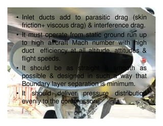
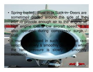
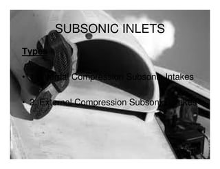
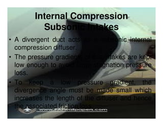
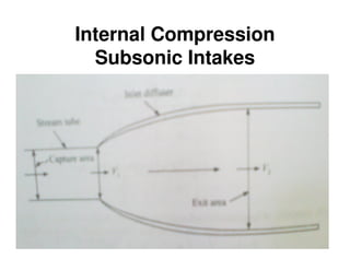
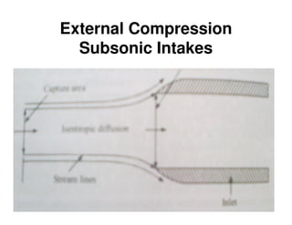
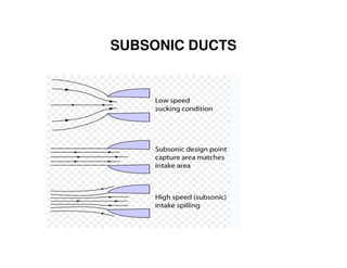
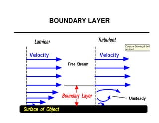
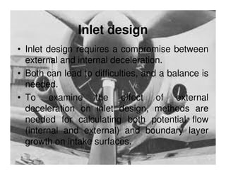
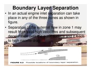


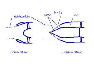


1) Jet engine inlets must supply the engine with airflow at high pressure to maximize thrust output. Inlet design is critical for both subsonic and supersonic aircraft. 2) For subsonic aircraft, inlets use either internal or external compression via divergent ducts to decelerate airflow without strong shockwaves. Supersonic inlets use convergent-divergent ducts with oblique shocks to decelerate airflow. 3) Proper inlet design considers boundary layer growth, external vs internal deceleration tradeoffs, and maintains high duct efficiency across a range of speeds and conditions. Inlet performance is measured by parameters like isentropic efficiency and stagnation pressure ratio.