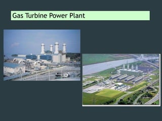
Gas turbine power_plant_new
•Download as PPT, PDF•
0 likes•88 views

Here is some knowledge about of Gas Turbine power plant that will help to upgrade the knowledge

Recommended
More Related Content
What's hot
What's hot (19)
Similar to Gas turbine power_plant_new
Similar to Gas turbine power_plant_new (20)
More from UthsoNandy
More from UthsoNandy (20)
Recently uploaded
Recently uploaded (20)
Gas turbine power_plant_new
- 1. Gas Turbine Power Plant
- 2. GAS TURBINES • Invented in 1930 by Frank Whittle • Patented in 1934 • First used for aircraft propulsion in 1942 on Me262 by Germans during second world war • Currently most of the aircrafts and ships use GT engines • Used for power generation • Manufacturers: General Electric, Pratt &Whitney, SNECMA, Rolls Royce, Honeywell, Siemens – Westinghouse, Alstom • Indian take: Kaveri Engine by GTRE (DRDO)
- 3. Selection of Site for Gas Turbine Power Plants The following factors should be considered while selecting a site for gas turbine power plant: 1. Distance from Load Centre: The site should be as near to the load centre as possible so that the transmission costs and losses are minimised. 2. Availability of Land: The land should be available at cheap rate in order to keep the capital cost of the plant low. 3. Availability of Fuel: The fuel should be easily available and at reasonable rate. 4. Availability of Transportation Facilities: The transportation facilities should be available. 5. Distance from Populated Area: The site should be away from thickly populated area because of noisy operation. 6. Type of Land: The land should be of high bearing capacity to withstand the load of the plant and also the vibrations transmitted to the foundations from compressors and turbines.
- 4. Gas turbine power plant Gas turbine: Working principle : Air is compressed(squeezed) to high pressure by a fan- like device called the compressor. Then fuel and compressed air are mixed in a combustion chamber and ignited. Hot gases are given off, which spin the turbine wheels. Most of the turbine’s power runs the compressor. Part of it drives the generator/machinery.
- 5. Gas turbine power plant… Gas turbine: Description: Gas turbines burn fuels such as oil, nature gas and pulverised(powdered) coal. Instead of using the heat to produce steam, as in steam turbines, gas turbines use the hot gases directly to turn the turbine blades. Gas turbines have three main parts: i) Air compressor ii) Combustion chamber iii) Turbine
- 6. Gas turbine power plant… Gas turbine: Air compressor: The air compressor and turbine are mounted at either end on a common horizontal axle(shaft), with the combustion chamber between them. Gas turbines are not self starting. A starting motor initially drives the compressor till the first combustion of fuel takes place, later, part of the turbine’s power runs the compressor. The air compressor sucks in air and compresses it, thereby increasing its pressure.
- 7. Gas turbine power plant… Gas turbine: Combustion chamber: In the combustion chamber, the compressed air combines with fuel and the resulting mixture is burnt. The greater the pressure of air, the better the fuel air mixture burns. Modern gas turbines usually use liquid fuel, but they may also use gaseous fuel, natural gas or gas produced artificially by gasification of a solid fuel. Note : The combination of air compressor and combustion chamber is called as gas generator.
- 8. Gas turbine power plant… Gas turbine: Turbine: o The burning gases expand rapidly and rush into the turbine, where they cause the turbine wheels to rotate. o Hot gases move through a multistage gas turbine. o Like in steam turbine, the gas turbine also has fixed(stationary) and moving(rotor) blades. o The stationary blades guide the moving gases to the rotor blades and adjust its velocity. o The shaft of the turbine is coupled to a generator or machinery to drive it.
- 9. Gas turbine power plant… Applications of gas turbine: Gas turbines are used to drive pumps, compressors and high speed cars. Used in aircraft and ships for their propulsion. They are not suitable for automobiles because of their very high speeds. Power generation(used for peak load and as stand-by unit). Note : Gas turbines run at even higher temperatures thansteam turbines, the temperature may be as high as 1100 – 12600C.
- 10. Layout of a gas turbine power plant
- 11. Layout of gas turbine power plant… Starting motor: Gas turbines are not self starting. They require a starting motor to first bring the turbine to the minimum speed called coming –in speed, for this purpose a starting motor is required. Low pressure compressor(LPC): The purpose of the compressor is to compress the air. Air from the atmosphere is drawn into the LPC and is compressed. Intercooler: The air after compression in the LPC is hot. It is cooled by the intercooler.The intercooler is circulated with cooling water.
- 12. Layout of gas turbine power plant… High pressure compressor(HPC): The air from the intercooler enters the HPC where it is further compressed to a high pressure. The compressed air passes through a regenerator. Regenerator(Heat exchanger): The air entering the combustion chamber(CC) for compressed air entering combustion chamber. combustion Combustionchamber: must be hot. The heat from the The fuel(natural gas, pulverized coal, exhaust gases is picked up by the kerosene or gasoline) is injected into the the combustion chamber. The fuel gets ignited because of the compressed air. The fuel along with the compressed air is ignited sometimes with a spark plug.
- 13. Layout of gas turbine power plant… High pressure compressor(HPC): The air from the intercooler enters the HPC where it is further compressed to a high pressure. The compressed air passes through a regenerator. Regenerator(Heat exchanger): The air entering the combustion chamber(CC) for combustion must be hot. The heat from the exhaust gases is picked up by the compressed air entering the combustion chamber. Combustion chamber: The fuel(natural gas, pulverized coal, kerosene or gasoline) is injected into the combustion chamber. The fuel gets ignited because of the compressed air. The fuel along with the compressed air is ignited sometimes with a spark
- 14. Layout of gas turbine power plant… High pressure turbine (HPT): In the beginning the starting motor runs the compressor shaft. The hot gases(products of combustion) expands through the high pressure turbine. It is important to note that when the HPT shaft rotates it infact drives the compressor shaft which is coupled to it. Now the HPT runs the compressor and the starting motor is stopped. Note : About 66% developed by of the power the gas turbine power plant is used to run the compressor. Only 34% of the power developed by the plant is used to generate electric power.
- 15. Layout of gas turbine power plant… Low pressure turbine (LPT): The purpose of the LPT is to produce electric power. The shaft of the LPT is directly coupled with the generator for producing electricity. combustion) after leaving The hot gases(products of the HPT is again sent to a combustion chamber where it further undergoes combustion. The exhaust gases after leaving the LPT passes through the regenerator exhausted before being through the chimney into the atmosphere. The heat from the hot gases is used to preheat the air entering the combustion chamber. This preheating of the air improves the efficiency of the combustion chamber.
- 16. Gas turbine power plant… Advantages of gas turbine power plant : Storage of fuel requires less area and handling is easy. The cost of maintenance is less. It is simple in construction. There is no need for boiler, condenser and other accessories as in the case of steam power plants. Cheaper fuel such as kerosene , paraffin, benzene and powdered coal can be used which are cheaper than petrol and diesel. Gas turbine plants can be used in water scarcity areas. Less pollution and less water is required. Disadvantages of gas turbine power plant : 66% of the power developed is used to drive the compressor. Therefore the gas turbine unit has a low thermal efficiency. The running speed of gas turbine is in the range of (40,000 to 100,000 rpm) and the operating temperature is as high as 1100 – 12600C. For this reason special metals and alloys have to be used for the various parts of the turbine. High frequency noise from the compressor is objectionable.
- 17. Compared to Steam-Turbine, Gas Turbine offers : 1. Greater Power for a given size and weight, 2. High Reliability, 3. Long Life, 4. More Convenient Operation. 5. Engine Start-up Time reduced from 4 hrs to less than 2 min…!! Gas Turbine Power Plants – Advantages
- 18. Gas Turbine Power Plants – Applications Two Major Application Areas: 1. Aircraft Propulsion 2. Electric Power Generation. Electric Power GenerationAircraft Propulsion
- 19. Made up of Four Internally Reversible processes: Brayton Closed Cycle – Analysis 1-2 2-3 3-4 4-1 Isentropic Compression (in a Compressor) Constant-Pressure Heat Addition Isentropic Expansion (in a Turbine) Constant-Pressure Hat Rejection
- 20. Back Work Ratio Back WorkRatio Compressor Work 1 TurbineWork 2 Usually, more than one-half of the Turbine Work Output is used to drive the Compressor. In contrast to Steam Power Plants, where Back Work Ratio is only a few percent. ..!! This is due to : 1. Liquid is compressed in Steam Power Plants instead of a gas. 2. Steady-Flow Work is proportional to Sp. Volume of the workingfluid. Therefore, the turbines used in Gas-Turbine Power Plants are larger thanthose used in Steam Power Plants of the same net power output…!!
- 21. Regenerative Brayton Cycle For the Brayton cycle, the turbine exhaust temperature is greater than the compressor exit temperature. Therefore, a heat exchanger can be placed between the hot gases leaving the turbine and the cooler gases leaving the compressor. This heat exchanger is called a regenerator or recuperator..
- 22. Gas Turbine Cycle – Intercooling Net Work Output of Gas Turbine can be ↑ by ↓ the Compressor WorkInput. Multistage + Intercooling…!!!
- 23. Gas Turbine Cycle – Intercooling Three Internally Reversible processes: 1-c Isentropic Compression, till Pr. is Pi c-d Constant-Pressure Cooling, ↓ from Tcto Td d-2 Isentropic Compression, State 2.
- 24. Gas Turbine Cycle – Reheat For Metallurgical Reasons, the Temperature of the Gaseous Combustion Products entering the turbine must be limited. This temperature can be controlled by providing Air in Excess of the Amount required to Burn the Fuel in the combustor. As a consequence, the gases exiting the combustor contain Sufficient Air to support the Combustion of Additional Fuel. Gas Turbine Power Plants take advantage of the Excess Air by means of a Multistage Turbine with a Reheat Combustor between the stages. With this arrangement the Net Work per Unit of Mass Flow can be increased. NOTE : Reheat is used for ↑ in Output Power. It may not ↑ the Efficiency…!!
- 25. Gas Turbine Cycle – Reheat After expansion from State 3 to State a in the first turbine, the gas is Reheated at Constant Pressure from State a to State b. The expansion is then completed in the second turbine from State b to State 4.
- 26. Gas Turbine Cycle – Intercooling + Reheat + Regenerator
- 27. Brayton with Intercooling, Reheat, & Regeneration