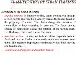
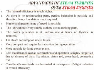
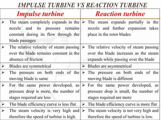
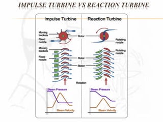
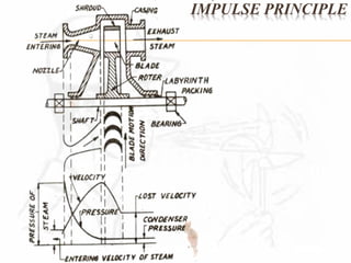
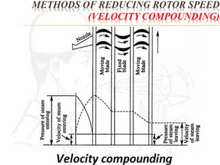
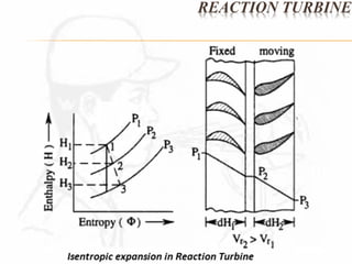
SlideShare a Scribd company logo
STEAM TURBINES
DEFINITION 
A steam turbine is a prime mover in 
which the potential energy of the steam is 
transformed into kinetic energy and later in 
its turn is transformed into the mechanical 
energy of rotation of the turbine shaft.
APPLICATIONS OF STEAM TURBINES 
 Power Generation 
 Transport
CLASSIFICATION OF STEAM TURBINES 
According to the action of steam: 
 Impulse turbine: In impulse turbine, steam coming out through 
a fixed nozzle at a very high velocity strikes the blades fixed on 
the periphery of a rotor. The blades change the direction of 
steam flow without changing its pressure. The force due to 
change of momentum causes the rotation of the turbine shaft. 
Ex: De-Laval, Curtis and Rateau Turbines 
 Reaction turbine: In reaction turbine, steam expands both in 
fixed and moving blades continuously as the steam passes over 
them. The pressure drop occurs continuously over both moving 
and fixed blades. 
 Combination of impulse and reaction turbine
CLASSIFICATION OF STEAM TURBINES 
According to the number of pressure stages: 
 Single stage turbines: These turbines are mostly used for 
driving centrifugal compressors, blowers and other similar 
machinery. 
 Multistage Impulse and Reaction turbines: They are made in a 
wide range of power capacities varying from small to large. 
According to the type of steam flow: 
 Axial turbines: In these turbines, steam flows in a direction 
parallel to the axis of the turbine rotor. 
 Radial turbines: In these turbines, steam flows in a direction 
perpendicular to the axis of the turbine, one or more low 
pressure stages are made axial.
CLASSIFICATION OF STEAM TURBINES 
According to the number of shafts: 
 Single shaft turbines 
 Multi-shaft turbines 
According to the method of governing: 
 Turbines with throttle governing: In these turbines, fresh steam 
enter through one or more (depending on the power developed) 
simultaneously operated throttle valves. 
 Turbines with nozzle governing: In these turbines, fresh steam 
enters through one or more consecutively opening regulators. 
 Turbines with by-pass governing: In these turbines, the steam 
besides being fed to the first stage is also directly fed to one, 
two or even three intermediate stages of the turbine.
CLASSIFICATION OF STEAM TURBINES 
According to the heat drop process: 
Condensing turbines with generators: In these turbines, steam at a pressure 
less than the atmospheric is directed to the condenser. The steam is also 
extracted from intermediate stages for feed water heating). The latent heat of 
exhaust steam during the process of condensation is completely lost in these 
turbines. 
Condensing turbines with one or more intermediate stage extractions: In 
these turbines, the steam is extracted from intermediate stages for industrial 
heating purposes. 
Back pressure turbines: In these turbines, the exhaust steam is utilized for 
industrial or heating purposes. Turbines with deteriorated vacuum can also be 
used in which exhaust steam may be used for heating and process purposes. 
Topping turbines: In these turbines, the exhaust steam is utilized in medium 
and low pressure condensing turbines. These turbines operate at high initial 
conditions of steam pressure and temperature, and are mostly used during 
extension of power station capacities, with a view to obtain better 
efficiencies.
CLASSIFICATION OF STEAM TURBINES 
According to the steam conditions at inlet to turbine: 
 Low pressure turbines: These turbines use steam at a pressure 
of 1.2 ata to 2 ata. 
 Medium pressure turbines: These turbines use steam up to a 
pressure of 40 ata. 
 High pressure turbines: These turbines use steam at a pressure 
above 40 ata. 
 Very high pressure turbines: These turbines use steam at a 
pressure of 170 ata and higher and temperatures of 550C and 
higher. 
 Supercritical pressure turbines: These turbines use steam at a 
pressure of 225 ata and higher.
CLASSIFICATION OF STEAM TURBINES 
According to their usage in industry: 
 Stationary turbines with constant speed of rotation: These 
turbines are primarily used for driving alternators. 
 Stationary turbines with variable speed of rotation: These 
turbines are meant for driving turbo-blowers, air circulators, 
pumps, etc. 
 Non-stationary turbines with variable speed: These turbines 
are usually employed in steamers, ships and railway 
locomotives.
ADVANTAGES OF STEAM TURBINES 
OVER STEAM ENGINES 
1. The thermal efficiency is much higher. 
2. As there is no reciprocating parts, perfect balancing is possible and 
therefore heavy foundation is not required. 
3. Higher and greater range of speed is possible. 
4. The lubrication is very simple as there are no rubbing parts. 
5. The power generation is at uniform rate & hence no flywheel is 
required. 
6. The steam consumption rate is lesser. 
7. More compact and require less attention during operation. 
8. More suitable for large power plants. 
9. Less maintenance cost as construction and operation is highly simplified 
due to absence of parts like piston, piston rod, cross head, connecting 
rod. 
10. Considerable overloads can be carried at the expense of slight reduction 
in overall efficiency.
IMPULSE TURBINE VS REACTION TURBINE 
Impulse turbine Reaction turbine 
 The steam completely expands in the 
nozzle and its pressure remains 
constant during its flow through the 
blade passages 
 The steam expands partially in the 
nozzle and further expansion takes 
place in the rotor blades 
 The relative velocity of steam passing 
over the blade remains constant in the 
absence of friction 
 The relative velocity of steam passing 
over the blade increases as the steam 
expands while passing over the blade 
 Blades are symmetrical  Blades are asymmetrical 
 The pressure on both ends of the 
moving blade is same 
 The pressure on both ends of the 
moving blade is different 
 For the same power developed, as 
pressure drop is more, the number of 
stages required are less 
 For the same power developed, as 
pressure drop is small, the number of 
stages required are more 
 The blade efficiency curve is less flat  The blade efficiency curve is more flat 
 The steam velocity is very high and 
therefore the speed of turbine is high. 
 The steam velocity is not very high and 
therefore the speed of turbine is low.
IMPULSE TURBINE VS REACTION TURBINE
SIMPLE IMPULSE TURBINE
IMPULSE PRINCIPLE 
 The impulse turbine consists basically of a rotor 
mounted on a shaft that is free to rotate in a set of 
bearings. 
 The outer rim of the rotor carries a set of curved 
blades, and the whole assembly is enclosed in an 
airtight case. 
 Nozzles direct steam against the blades and turn the 
rotor. The energy to rotate an impulse turbine is 
derived from the kinetic energy of the steam 
flowing through the nozzles. 
 The term impulse means that the force that turns the 
turbine comes from the impact of the steam on the 
blades.
IMPULSE PRINCIPLE 
The toy pinwheel can be used to study some of the basic principles of 
turbines. When we blow on the rim of the wheel, it spins rapidly. The 
harder we blow, the faster it turns. 
The steam turbine operates on the same principle, except it uses the 
kinetic energy from the steam as it leaves a steam nozzle rather 
than air. 
Steam nozzles are located at the turbine inlet. As the steam passes 
through a steam nozzle, potential energy is converted to kinetic 
energy. 
This steam is directed towards the turbine blades and turns the rotor. 
The velocity of the steam is reduced in passing over the blades. 
Some of its kinetic energy has been transferred to the blades 
to turn the rotor. 
Impulse turbines may be used to drive forced draft blowers, pumps, 
and main propulsion turbines.
BASICS OF IMPULSE TURBINE 
 In impulse turbine, steam coming out through a fixed 
nozzle at a very high velocity strikes the blades fixed on 
the periphery of a rotor. 
 The blades change the direction of steam flow without 
changing its pressure. 
 The force due to change of momentum causes the rotation 
of the turbine shaft. 
 Examples: De-Laval, Curtis and Rateau turbines.
CONSTRUCTION & WORKING PRINCIPLE 
OF IMPULSE PRINCIPLE 
It primarily consists of a nozzle or a set of nozzles, 
a rotor mounted on a shaft, one set of moving 
blades attached to the rotor and a casing. 
A simple impulse turbine is also called De-Laval 
turbine, after the name of its inventor 
This turbine is called simple impulse turbine since 
the expansion of the steam takes place in one set of 
nozzles.
IMPULSE PRINCIPLE
 The uppermost portion of the diagram shows a longitudinal 
section through the upper half of the turbine. 
 The middle portion shows the actual shape of the nozzle and 
blading. 
 The bottom portion shows the variation of absolute velocity 
and absolute pressure during the flow of steam through 
passage of nozzles and blades. 
 The expansion of steam from its initial pressure (steam chest 
pressure) to final pressure (condenser pressure) takes place in 
one set of nozzles. 
 Due to high drop in pressure in the nozzles, the velocity of 
steam in the nozzles increases. 
IMPULSE TURBINE
IMPULSE TURBINE 
 The steam leaves the nozzle with a very high velocity and 
strikes the blades of the turbine mounted on a wheel with this 
high velocity. 
 The loss of energy due to this higher exit velocity is 
commonly known as carry over loss (or) leaving loss. 
 The pressure of the steam when it moves over the blades 
remains constant but the velocity decreases. 
 The exit/leaving/lost velocity may amount to 3.3 percent of 
the nozzle outlet velocity. 
 Also since all the KE is to be absorbed by one ring of the 
moving blades only, the velocity of wheel is too high (varying 
from 25000 to 30000 RPM). 
 However, this wheel or rotor speed can be reduced by 
adopting the method of compounding of turbines.
DISADVANTAGES OF IMPULSE TURBINE 
1. Since all the KE of the high velocity steam has to be 
absorbed in only one ring of moving blades, the velocity 
of the turbine is too high i.e. up to 30000 RPM for 
practical purposes. 
2. The velocity of the steam at exit is sufficiently high which 
means that there is a considerable loss of KE.
VELOCITY DIAGRAM / VELOCITY TRIANGLE 
INLET VELOCITY TRIANGLE 
OUTLET VELOCITY TRIANGLE
COMBINED VELOCITY TRIANGLE
NOTATIONS
WORK OUTPUT, POWER, 
BLADE EFFICIENCY & STAGE EFFICIENCY 
Force in the tangential direction  
Rate of change of momentum in the tangential direction. 
  
Mass per second change in velocity Newtons 
  Newtons 
w1 w2  m V V 
Force in the axial direction  
Rate of change of momentum in the axial direction. 
(axial thrust)   Newtons 
a1 a2  m V V 
Work done by steam on blades   N -m/s 2 m V V u w1 w   
  
kW 
m V V u w1 w 
Power developed by the turbine 2  
 
1000 
    
m V V u 2 2 
2u V V u 
w1 w 
2 
1 
w1 w 
2 
1 
V 
mV 
1 
2 
Work done on the blade(s) 
Energy supplied to the blade(s) 
Blade efficiency 
 
 
 
  
  N-m/s 
1 
Energy lost due to blade friction 2 
2 
r2 
2 
r1  mV V 
  
  
  
m V V u 2 
V V u 
w1 w 
d 
 
w1 w 
1 
H 
2 
m H H 
2 
Work done on the blade(s) 
Total energy supplied per stage 
Stage efficiency 
 
 
 
  
   Heat drop in the nozzle ring d 1 2 where H H H
MAXIMUM WORK & 
MAXIMUM DIAGRAM EFFICIENCY 
From the combined velocity triangle (diagram), we have 
V V V u w r    1 1 1 1 1 cos cos V V V u w r    2 2 2 2 2 and cos cos 
V  KC 
V 
r 
 
 
cos 
 
2 2 
V V V V V r 
      cos 1 
cos cos cos 1 1 1 
  
 w 1 w 2 r 1 1 r 2 2 r 1 1  
V 
r 
 
 
 
cos 
 
1 1 
   
2 
1 
r 
V 
r 
V 
K  where and 
 
2 
1 
cos 
cos 
 
C  
V V V u KC w w   cos  1 1 2 1 1 (or)  
V cos  u1 KCu 1 1  
Rate of doing work per kg of steam per second = 
V u KC 
1 1 cos 1 
Blade speed ratio 
u 
  
V 
1 
 
   
2 
1 
V 
b 
  
 
 
Diagram efficiency,  
Let, 
  KC b  2 cos  1 2 
1 Then, Diagram efficiency,    
MAXIMUM WORK & 
MAXIMUM DIAGRAM EFFICIENCY 
 If the values of 1, K and C are assumed to be constant, then diagram 
efficiency depends only on the value of blade speed ratio,  
 In order to determine the optimum value of for maximum diagram 
efficiency, 
 0 
 
 b 
 
 
 Then,  becomes,  = 
cos 1  
2
MAXIMUM WORK & 
MAXIMUM DIAGRAM EFFICIENCY 
cos 
Maximum diagram efficiency = 
cos 
 
 
      
cos 
2 1 1 
2 
1 
4 
  .cos 
 
2 
2 
1 
2 
1 
1 
max 
  
 
 
 KC KC b    
 
Note: If the blade is symmetrical & friction is absent, then, we have 
1=2 and K = C = 1 
Then, maximum diagram efficiency, (b)max = cos21 
V cos u1 KCu 1 1 Work done/kg of steam/second =  
2 Then maximum rate of doing work/kg of steam/second  2u
METHODS OF REDUCING ROTOR SPEED 
(COMPOUNDING OF TURBINES) 
If high velocity of steam is allowed to flow through one row of 
moving blades, it produces a rotor speed of about 30000 rpm 
which is too high for practical use. 
It is therefore essential to incorporate some improvements for 
practical use and also to achieve high performance. 
This is possible by making use of more than one set of nozzles, 
and rotors, in a series, keyed to the shaft so that either the steam 
pressure or the jet velocity is absorbed by the turbine in stages. 
This is called compounding of turbines. 
The high rotational speed of the turbine can be reduced by the 
following methods of compounding: 
1) Velocity compounding 
2) Pressure compounding, and 
3) Pressure-Velocity compounding
METHODS OF REDUCING ROTOR SPEED 
(VELOCITY COMPOUNDING)
METHODS OF REDUCING ROTOR SPEED 
(VELOCITY COMPOUNDING) 
 It consists of a set of nozzles and a few rows of moving blades which are fixed to 
the shaft and rows of fixed blades which are attached to the casing. 
 As shown in figure, the two rows of moving blades are separated by a row of fixed 
blades. 
 The high velocity steam first enters the first row of moving blades, where some 
portion of the velocity is absorbed. 
 Then it enters the ring of fixed blades where the direction of steam is changed to suit 
the second ring of moving blades. There is no change in the velocity as the steam 
passes over the fixed blades. 
 The steam then passes on to the second row of moving blades where the velocity is 
further reduced. Thus a fall in velocity occurs every time when the steam passes 
over the row of moving blades. Steam thus leaves the turbine with a low velocity. 
 The variation of pressure and velocity of steam as it passes over the moving and 
fixed blades is shown in the figure. It is clear from the figure that the pressure drop 
takes place only in the nozzle and there is no further drop of pressure as it passes 
over the moving blades. 
 This method of velocity compounding is used in Curtis turbine after it was first 
proposed by C.G. Curtis
METHODS OF REDUCING ROTOR SPEED 
ADVANTAGES 
(VELOCITY COMPOUNDING) 
1) The arrangement has less number of stages and hence less 
initial cost 
2) The arrangement requires less space 
3) The system is reliable and easy to operate 
4) The fall of pressure in the nozzle is considerable, so the 
turbine itself need not work in high pressure surroundings and 
the turbine housing need not be very strong 
DISADVANTAGES 
1) More friction losses due to very high velocity in the nozzles 
2) Less efficiency because ratio of blade velocity to steam 
velocity is not optimum 
3) Power developed in the later rows is only fraction of first row. 
Still all the stages require same space, material and cost.
METHODS OF REDUCING ROTOR SPEED 
(PRESSURE COMPOUNDING)
METHODS OF REDUCING ROTOR SPEED 
(PRESSURE COMPOUNDING) 
 It consists of a number of fixed nozzles which are incorporated 
between the rings of moving blades. The moving blades are keyed to 
the shaft. 
 Here the pressure drop is done in a number of stages. Each stage 
consists of a set of nozzles and a ring of moving blades. 
 Steam from the boiler passes through the first set of nozzles where it 
expands partially. Nearly all its velocity is absorbed when it passes 
over the first set of moving blades. 
 It is further passed to the second set of fixed nozzles where it is 
partially expanded again and through the second set of moving blades 
where the velocity of steam is almost absorbed. This process is 
repeated till steam leaves at condenser pressure. 
 By reducing the pressure in stages, the velocity of steam entering the 
moving blades is considerably reduced. Hence the speed of the rotor 
is reduced. Rateau & Zoelly turbines use this method of 
compounding.
METHODS OF REDUCING ROTOR SPEED 
(PRESSURE-VELOCITY COMPOUNDING) 
1) In this method of compounding, both pressure and 
velocity compounding methods are utilized. 
2) The total drop in steam pressure is carried out in 
two stages and the velocity obtained in each stage 
is also compounded. 
3) The ring of nozzles are fixed at the beginning of 
each stage and pressure remains constant during 
each stage. 
4) This method of compounding is used in Curtis 
and More turbines.
METHODS OF REDUCING ROTOR SPEED 
(PRESSURE-VELOCITY COMPOUNDING)
REACTION TURBINE 
A turbine in which steam pressure decreases gradually while 
expanding through the moving blades as well as the fixed blades is 
known as reaction turbine. 
It consists of a large number of stages, each stage consisting of set of 
fixed and moving blades. The heat drop takes place throughout in both 
fixed and moving blades. 
No nozzles are provided in a reaction turbine. The fixed blades act 
both as nozzles in which velocity of steam increased and direct the 
steam to enter the ring of moving blades. As pressure drop takes place 
both in the fixed and moving blades, all the blades are nozzle shaped. 
The steam expands while flowing over the moving blades and thus 
gives reaction to the moving blades. Hence the turbine is called 
reaction turbine. 
The fixed blades are attached to the casing whereas moving blades are 
fixed with the rotor. 
It is also called Parson’s reaction turbine.
REACTION TURBINE
WORK OUTPUT & POWER 
IN REACTION TURBINE 
The work done per kg of steam in the stage (per pair) = 
muV V N m s w w / 1 2   
where, m = mass of steam flowing over blades in kg/s 
1 2  Power developed (per pair) = 
work done per kg of steam in the stage per pair 
  
u V V 
1 2  
H 
 
Efficiency, 
Enthalpy drop in the stage per pair 
Efficiency, 
w w 
1000 
 
  
 
uV V N m w w   1 2 
The work done per kg of steam per second in the stage (per pair) = 
  
kW 
mu V Vw w 
1000 
where, H = Enthalpy drop in the stage 
per pair in kJ/kg
DEGREE OF REACTION 
IN REACTION TURBINE
WORK DONE & EFFICIENCY 
IIN REACTION TURBINE
WORK DONE & EFFICIENCY 
IN REACTION TURBINE
WORK DONE & EFFICIENCY 
IN REACTION TURBINE
GOVERNING OF TURBINES 
Governing is the method of maintaining the speed of the 
turbine constant irrespective of variation of the load on 
the turbine. 
A governor is used for achieving this purpose which 
regulates the supply of steam to the turbine in such a way 
that the speed of the turbine is maintained as far as 
possible a constant under varying load conditions. 
The various methods of governing of steam turbines are: 
1) Throttle governing 
2) Nozzle governing 
3) By-pass governing 
4) Combination of (1) & (2) or (2) & (3)
GOVERNING OF TURBINES 
(THROTTLE GOVERNING)
GOVERNING OF TURBINES 
(THROTTLE GOVERNING) 
WILLIAN’S LINE
GOVERNING OF TURBINES 
(NOZZLE GOVERNING)
GOVERNING OF TURBINES 
(BY-PASS GOVERNING)
LOSSES IN STEAM TURBINES 
 Residual velocity loss 
 Losses in regulating valves 
 Loss due to steam friction in nozzle 
 Loss due to leakage 
 Loss due to mechanical friction 
 Loss due to wetness of steam 
 Radiation loss
EFFECT OF BLADE FRICTION 
IN STEAM TURBINES
OVERALL EFFICIENCY 
& REHEAT FACTOR 
Reheat factor: 
It is defined as the ratio of cumulative heat drop to the 
adiabatic heat drop in all the stages of the turbine. The 
value of reheat factor depends on the type and 
efficiency of the turbine, the average value being 1.05. 
A B A B A B 
1 1 2 2 3 3   
A D 
Cumulative heat drop 
Adiabatic heat drop 
Reheat factor 
1 
  
Overall efficiency: 
It is defined as the ratio of total useful heat drop to the 
total heat supplied. 
A C A C A C 
1 1 2 2 3 3 
H - h 
A1 D 
Total useful heat drop 
Total heat supplied 
Overall efficiency 
  
 

More Related Content

What's hot

Steam turbine Working
Steam turbine WorkingSteam turbine Working
Steam turbine Working
Chaudhry Hassan Ali
 
Degree of reaction
Degree of reactionDegree of reaction
Degree of reaction
Harshit Jain
 
Basics of Gas Turbine Power Plant
Basics of Gas Turbine Power PlantBasics of Gas Turbine Power Plant
Basics of Gas Turbine Power Plant
S.Vijaya Bhaskar
 
Chapter 4 Gas Turbine
Chapter 4 Gas TurbineChapter 4 Gas Turbine
Chapter 4 Gas Turbine
ANIKET SURYAWANSHI
 
Steam turbine
Steam turbineSteam turbine
Steam turbine
muhammad mubashir
 
Gas turbines
Gas turbines Gas turbines
Gas turbines
krishna khot
 
[PPT] on Steam Turbine
[PPT] on Steam Turbine[PPT] on Steam Turbine
[PPT] on Steam Turbine
Sumit Sharma
 
Chapter 3 centrifugal comp
Chapter 3 centrifugal compChapter 3 centrifugal comp
Chapter 3 centrifugal comp
Novak Djokovich
 
Boiler performance (Part 1) - Equivalent evaporation - Notes
Boiler performance (Part 1) - Equivalent evaporation - NotesBoiler performance (Part 1) - Equivalent evaporation - Notes
Boiler performance (Part 1) - Equivalent evaporation - Notes
AVDHESH TYAGI
 
Impulse and reaction turbines
Impulse and reaction turbinesImpulse and reaction turbines
Impulse and reaction turbines
Yasir Hashmi
 
Steam nozzle
Steam nozzleSteam nozzle
steam turbine govering system
steam turbine govering systemsteam turbine govering system
steam turbine govering systemmitravanu mishra
 
Power cycles 1
Power cycles 1Power cycles 1
Power cycles 1
Nihal Senanayake
 
Steam Condensers
Steam CondensersSteam Condensers
Steam Condensers
Hrishikesh Devan
 
STEAM NOZZLES
STEAM NOZZLESSTEAM NOZZLES
STEAM NOZZLES
Vanita Thakkar
 
Rankine cycle
Rankine cycleRankine cycle
Rankine cycle
Ashish Kumar Jain
 
centrifugal compressors overview
centrifugal compressors overviewcentrifugal compressors overview
centrifugal compressors overview
Usman Ali
 
Basics of Compressor
Basics of CompressorBasics of Compressor
Basics of CompressorSLA1987
 
Nozzle
NozzleNozzle
01 regenerative feed heating
01 regenerative feed heating01 regenerative feed heating
01 regenerative feed heating
Anil Palamwar
 

What's hot (20)

Steam turbine Working
Steam turbine WorkingSteam turbine Working
Steam turbine Working
 
Degree of reaction
Degree of reactionDegree of reaction
Degree of reaction
 
Basics of Gas Turbine Power Plant
Basics of Gas Turbine Power PlantBasics of Gas Turbine Power Plant
Basics of Gas Turbine Power Plant
 
Chapter 4 Gas Turbine
Chapter 4 Gas TurbineChapter 4 Gas Turbine
Chapter 4 Gas Turbine
 
Steam turbine
Steam turbineSteam turbine
Steam turbine
 
Gas turbines
Gas turbines Gas turbines
Gas turbines
 
[PPT] on Steam Turbine
[PPT] on Steam Turbine[PPT] on Steam Turbine
[PPT] on Steam Turbine
 
Chapter 3 centrifugal comp
Chapter 3 centrifugal compChapter 3 centrifugal comp
Chapter 3 centrifugal comp
 
Boiler performance (Part 1) - Equivalent evaporation - Notes
Boiler performance (Part 1) - Equivalent evaporation - NotesBoiler performance (Part 1) - Equivalent evaporation - Notes
Boiler performance (Part 1) - Equivalent evaporation - Notes
 
Impulse and reaction turbines
Impulse and reaction turbinesImpulse and reaction turbines
Impulse and reaction turbines
 
Steam nozzle
Steam nozzleSteam nozzle
Steam nozzle
 
steam turbine govering system
steam turbine govering systemsteam turbine govering system
steam turbine govering system
 
Power cycles 1
Power cycles 1Power cycles 1
Power cycles 1
 
Steam Condensers
Steam CondensersSteam Condensers
Steam Condensers
 
STEAM NOZZLES
STEAM NOZZLESSTEAM NOZZLES
STEAM NOZZLES
 
Rankine cycle
Rankine cycleRankine cycle
Rankine cycle
 
centrifugal compressors overview
centrifugal compressors overviewcentrifugal compressors overview
centrifugal compressors overview
 
Basics of Compressor
Basics of CompressorBasics of Compressor
Basics of Compressor
 
Nozzle
NozzleNozzle
Nozzle
 
01 regenerative feed heating
01 regenerative feed heating01 regenerative feed heating
01 regenerative feed heating
 

Similar to Steam Turbines

Steam Turbine_edit.pptx
Steam Turbine_edit.pptxSteam Turbine_edit.pptx
Steam Turbine_edit.pptx
KrishhGupta
 
steam turbine.pptx
steam turbine.pptxsteam turbine.pptx
steam turbine.pptx
poonamChaudhary60
 
MODULE-V_STEAM TURBINES.pptx
MODULE-V_STEAM TURBINES.pptxMODULE-V_STEAM TURBINES.pptx
MODULE-V_STEAM TURBINES.pptx
DhruvBagade
 
Steam turbine and its types
Steam turbine and its typesSteam turbine and its types
Steam turbine and its types
Sanila Khalid
 
steam turbines
steam turbinessteam turbines
steam turbines
ssuserc01042
 
STM TURB.pdf
STM TURB.pdfSTM TURB.pdf
STM TURB.pdf
KAhmedRehman
 
Steam Turbine.pdf
Steam Turbine.pdfSteam Turbine.pdf
Steam Turbine.pdf
AnuragSingh292690
 
STEAM AND GAS TURBINES ppt
STEAM AND GAS TURBINES pptSTEAM AND GAS TURBINES ppt
STEAM AND GAS TURBINES ppt
ANKIT GUPTA
 
STEAM TURBINE BASIC
STEAM TURBINE BASIC STEAM TURBINE BASIC
STEAM TURBINE BASIC
Nguyen Phuong Dong
 
Steam turbine
Steam turbineSteam turbine
Steam turbine
Muhammad Yahya
 
Turbines
TurbinesTurbines
Turbine and it's classification.pptx
Turbine and it's classification.pptxTurbine and it's classification.pptx
Turbine and it's classification.pptx
Umar Saeed
 
Turbine section module 15.6
Turbine section module 15.6Turbine section module 15.6
Turbine section module 15.6
Dushan Wijesingha
 
Turbine
TurbineTurbine
Turbine
Help+
 
4PS21CS045.pdf
4PS21CS045.pdf4PS21CS045.pdf
4PS21CS045.pdf
LaxmiSingh429957
 
Advanced in turbocharging
Advanced in turbochargingAdvanced in turbocharging
Advanced in turbocharging
AkashDave12
 
Steam turbine
Steam turbineSteam turbine
Steam turbine
nell0511
 

Similar to Steam Turbines (20)

Steam Turbine_edit.pptx
Steam Turbine_edit.pptxSteam Turbine_edit.pptx
Steam Turbine_edit.pptx
 
steam turbine.pptx
steam turbine.pptxsteam turbine.pptx
steam turbine.pptx
 
Steam turbine
Steam turbineSteam turbine
Steam turbine
 
bhel_report_STM
bhel_report_STMbhel_report_STM
bhel_report_STM
 
MODULE-V_STEAM TURBINES.pptx
MODULE-V_STEAM TURBINES.pptxMODULE-V_STEAM TURBINES.pptx
MODULE-V_STEAM TURBINES.pptx
 
Steam turbine and its types
Steam turbine and its typesSteam turbine and its types
Steam turbine and its types
 
steam turbines
steam turbinessteam turbines
steam turbines
 
STM TURB.pdf
STM TURB.pdfSTM TURB.pdf
STM TURB.pdf
 
Steam Turbine.pdf
Steam Turbine.pdfSteam Turbine.pdf
Steam Turbine.pdf
 
STEAM AND GAS TURBINES ppt
STEAM AND GAS TURBINES pptSTEAM AND GAS TURBINES ppt
STEAM AND GAS TURBINES ppt
 
STEAM TURBINE BASIC
STEAM TURBINE BASIC STEAM TURBINE BASIC
STEAM TURBINE BASIC
 
Turbines
TurbinesTurbines
Turbines
 
Steam turbine
Steam turbineSteam turbine
Steam turbine
 
Turbines
TurbinesTurbines
Turbines
 
Turbine and it's classification.pptx
Turbine and it's classification.pptxTurbine and it's classification.pptx
Turbine and it's classification.pptx
 
Turbine section module 15.6
Turbine section module 15.6Turbine section module 15.6
Turbine section module 15.6
 
Turbine
TurbineTurbine
Turbine
 
4PS21CS045.pdf
4PS21CS045.pdf4PS21CS045.pdf
4PS21CS045.pdf
 
Advanced in turbocharging
Advanced in turbochargingAdvanced in turbocharging
Advanced in turbocharging
 
Steam turbine
Steam turbineSteam turbine
Steam turbine
 

Recently uploaded

Architectural Portfolio Sean Lockwood
Architectural Portfolio Sean LockwoodArchitectural Portfolio Sean Lockwood
Architectural Portfolio Sean Lockwood
seandesed
 
Pile Foundation by Venkatesh Taduvai (Sub Geotechnical Engineering II)-conver...
Pile Foundation by Venkatesh Taduvai (Sub Geotechnical Engineering II)-conver...Pile Foundation by Venkatesh Taduvai (Sub Geotechnical Engineering II)-conver...
Pile Foundation by Venkatesh Taduvai (Sub Geotechnical Engineering II)-conver...
AJAYKUMARPUND1
 
Quality defects in TMT Bars, Possible causes and Potential Solutions.
Quality defects in TMT Bars, Possible causes and Potential Solutions.Quality defects in TMT Bars, Possible causes and Potential Solutions.
Quality defects in TMT Bars, Possible causes and Potential Solutions.
PrashantGoswami42
 
WATER CRISIS and its solutions-pptx 1234
WATER CRISIS and its solutions-pptx 1234WATER CRISIS and its solutions-pptx 1234
WATER CRISIS and its solutions-pptx 1234
AafreenAbuthahir2
 
The role of big data in decision making.
The role of big data in decision making.The role of big data in decision making.
The role of big data in decision making.
ankuprajapati0525
 
Nuclear Power Economics and Structuring 2024
Nuclear Power Economics and Structuring 2024Nuclear Power Economics and Structuring 2024
Nuclear Power Economics and Structuring 2024
Massimo Talia
 
HYDROPOWER - Hydroelectric power generation
HYDROPOWER - Hydroelectric power generationHYDROPOWER - Hydroelectric power generation
HYDROPOWER - Hydroelectric power generation
Robbie Edward Sayers
 
Railway Signalling Principles Edition 3.pdf
Railway Signalling Principles Edition 3.pdfRailway Signalling Principles Edition 3.pdf
Railway Signalling Principles Edition 3.pdf
TeeVichai
 
Top 10 Oil and Gas Projects in Saudi Arabia 2024.pdf
Top 10 Oil and Gas Projects in Saudi Arabia 2024.pdfTop 10 Oil and Gas Projects in Saudi Arabia 2024.pdf
Top 10 Oil and Gas Projects in Saudi Arabia 2024.pdf
Teleport Manpower Consultant
 
Forklift Classes Overview by Intella Parts
Forklift Classes Overview by Intella PartsForklift Classes Overview by Intella Parts
Forklift Classes Overview by Intella Parts
Intella Parts
 
J.Yang, ICLR 2024, MLILAB, KAIST AI.pdf
J.Yang,  ICLR 2024, MLILAB, KAIST AI.pdfJ.Yang,  ICLR 2024, MLILAB, KAIST AI.pdf
J.Yang, ICLR 2024, MLILAB, KAIST AI.pdf
MLILAB
 
Event Management System Vb Net Project Report.pdf
Event Management System Vb Net  Project Report.pdfEvent Management System Vb Net  Project Report.pdf
Event Management System Vb Net Project Report.pdf
Kamal Acharya
 
Cosmetic shop management system project report.pdf
Cosmetic shop management system project report.pdfCosmetic shop management system project report.pdf
Cosmetic shop management system project report.pdf
Kamal Acharya
 
weather web application report.pdf
weather web application report.pdfweather web application report.pdf
weather web application report.pdf
Pratik Pawar
 
Standard Reomte Control Interface - Neometrix
Standard Reomte Control Interface - NeometrixStandard Reomte Control Interface - Neometrix
Standard Reomte Control Interface - Neometrix
Neometrix_Engineering_Pvt_Ltd
 
NO1 Uk best vashikaran specialist in delhi vashikaran baba near me online vas...
NO1 Uk best vashikaran specialist in delhi vashikaran baba near me online vas...NO1 Uk best vashikaran specialist in delhi vashikaran baba near me online vas...
NO1 Uk best vashikaran specialist in delhi vashikaran baba near me online vas...
Amil Baba Dawood bangali
 
一比一原版(SFU毕业证)西蒙菲莎大学毕业证成绩单如何办理
一比一原版(SFU毕业证)西蒙菲莎大学毕业证成绩单如何办理一比一原版(SFU毕业证)西蒙菲莎大学毕业证成绩单如何办理
一比一原版(SFU毕业证)西蒙菲莎大学毕业证成绩单如何办理
bakpo1
 
block diagram and signal flow graph representation
block diagram and signal flow graph representationblock diagram and signal flow graph representation
block diagram and signal flow graph representation
Divya Somashekar
 
Student information management system project report ii.pdf
Student information management system project report ii.pdfStudent information management system project report ii.pdf
Student information management system project report ii.pdf
Kamal Acharya
 
Democratizing Fuzzing at Scale by Abhishek Arya
Democratizing Fuzzing at Scale by Abhishek AryaDemocratizing Fuzzing at Scale by Abhishek Arya
Democratizing Fuzzing at Scale by Abhishek Arya
abh.arya
 

Recently uploaded (20)

Architectural Portfolio Sean Lockwood
Architectural Portfolio Sean LockwoodArchitectural Portfolio Sean Lockwood
Architectural Portfolio Sean Lockwood
 
Pile Foundation by Venkatesh Taduvai (Sub Geotechnical Engineering II)-conver...
Pile Foundation by Venkatesh Taduvai (Sub Geotechnical Engineering II)-conver...Pile Foundation by Venkatesh Taduvai (Sub Geotechnical Engineering II)-conver...
Pile Foundation by Venkatesh Taduvai (Sub Geotechnical Engineering II)-conver...
 
Quality defects in TMT Bars, Possible causes and Potential Solutions.
Quality defects in TMT Bars, Possible causes and Potential Solutions.Quality defects in TMT Bars, Possible causes and Potential Solutions.
Quality defects in TMT Bars, Possible causes and Potential Solutions.
 
WATER CRISIS and its solutions-pptx 1234
WATER CRISIS and its solutions-pptx 1234WATER CRISIS and its solutions-pptx 1234
WATER CRISIS and its solutions-pptx 1234
 
The role of big data in decision making.
The role of big data in decision making.The role of big data in decision making.
The role of big data in decision making.
 
Nuclear Power Economics and Structuring 2024
Nuclear Power Economics and Structuring 2024Nuclear Power Economics and Structuring 2024
Nuclear Power Economics and Structuring 2024
 
HYDROPOWER - Hydroelectric power generation
HYDROPOWER - Hydroelectric power generationHYDROPOWER - Hydroelectric power generation
HYDROPOWER - Hydroelectric power generation
 
Railway Signalling Principles Edition 3.pdf
Railway Signalling Principles Edition 3.pdfRailway Signalling Principles Edition 3.pdf
Railway Signalling Principles Edition 3.pdf
 
Top 10 Oil and Gas Projects in Saudi Arabia 2024.pdf
Top 10 Oil and Gas Projects in Saudi Arabia 2024.pdfTop 10 Oil and Gas Projects in Saudi Arabia 2024.pdf
Top 10 Oil and Gas Projects in Saudi Arabia 2024.pdf
 
Forklift Classes Overview by Intella Parts
Forklift Classes Overview by Intella PartsForklift Classes Overview by Intella Parts
Forklift Classes Overview by Intella Parts
 
J.Yang, ICLR 2024, MLILAB, KAIST AI.pdf
J.Yang,  ICLR 2024, MLILAB, KAIST AI.pdfJ.Yang,  ICLR 2024, MLILAB, KAIST AI.pdf
J.Yang, ICLR 2024, MLILAB, KAIST AI.pdf
 
Event Management System Vb Net Project Report.pdf
Event Management System Vb Net  Project Report.pdfEvent Management System Vb Net  Project Report.pdf
Event Management System Vb Net Project Report.pdf
 
Cosmetic shop management system project report.pdf
Cosmetic shop management system project report.pdfCosmetic shop management system project report.pdf
Cosmetic shop management system project report.pdf
 
weather web application report.pdf
weather web application report.pdfweather web application report.pdf
weather web application report.pdf
 
Standard Reomte Control Interface - Neometrix
Standard Reomte Control Interface - NeometrixStandard Reomte Control Interface - Neometrix
Standard Reomte Control Interface - Neometrix
 
NO1 Uk best vashikaran specialist in delhi vashikaran baba near me online vas...
NO1 Uk best vashikaran specialist in delhi vashikaran baba near me online vas...NO1 Uk best vashikaran specialist in delhi vashikaran baba near me online vas...
NO1 Uk best vashikaran specialist in delhi vashikaran baba near me online vas...
 
一比一原版(SFU毕业证)西蒙菲莎大学毕业证成绩单如何办理
一比一原版(SFU毕业证)西蒙菲莎大学毕业证成绩单如何办理一比一原版(SFU毕业证)西蒙菲莎大学毕业证成绩单如何办理
一比一原版(SFU毕业证)西蒙菲莎大学毕业证成绩单如何办理
 
block diagram and signal flow graph representation
block diagram and signal flow graph representationblock diagram and signal flow graph representation
block diagram and signal flow graph representation
 
Student information management system project report ii.pdf
Student information management system project report ii.pdfStudent information management system project report ii.pdf
Student information management system project report ii.pdf
 
Democratizing Fuzzing at Scale by Abhishek Arya
Democratizing Fuzzing at Scale by Abhishek AryaDemocratizing Fuzzing at Scale by Abhishek Arya
Democratizing Fuzzing at Scale by Abhishek Arya
 

Steam Turbines

  • 2. DEFINITION A steam turbine is a prime mover in which the potential energy of the steam is transformed into kinetic energy and later in its turn is transformed into the mechanical energy of rotation of the turbine shaft.
  • 3. APPLICATIONS OF STEAM TURBINES  Power Generation  Transport
  • 4. CLASSIFICATION OF STEAM TURBINES According to the action of steam:  Impulse turbine: In impulse turbine, steam coming out through a fixed nozzle at a very high velocity strikes the blades fixed on the periphery of a rotor. The blades change the direction of steam flow without changing its pressure. The force due to change of momentum causes the rotation of the turbine shaft. Ex: De-Laval, Curtis and Rateau Turbines  Reaction turbine: In reaction turbine, steam expands both in fixed and moving blades continuously as the steam passes over them. The pressure drop occurs continuously over both moving and fixed blades.  Combination of impulse and reaction turbine
  • 5. CLASSIFICATION OF STEAM TURBINES According to the number of pressure stages:  Single stage turbines: These turbines are mostly used for driving centrifugal compressors, blowers and other similar machinery.  Multistage Impulse and Reaction turbines: They are made in a wide range of power capacities varying from small to large. According to the type of steam flow:  Axial turbines: In these turbines, steam flows in a direction parallel to the axis of the turbine rotor.  Radial turbines: In these turbines, steam flows in a direction perpendicular to the axis of the turbine, one or more low pressure stages are made axial.
  • 6. CLASSIFICATION OF STEAM TURBINES According to the number of shafts:  Single shaft turbines  Multi-shaft turbines According to the method of governing:  Turbines with throttle governing: In these turbines, fresh steam enter through one or more (depending on the power developed) simultaneously operated throttle valves.  Turbines with nozzle governing: In these turbines, fresh steam enters through one or more consecutively opening regulators.  Turbines with by-pass governing: In these turbines, the steam besides being fed to the first stage is also directly fed to one, two or even three intermediate stages of the turbine.
  • 7. CLASSIFICATION OF STEAM TURBINES According to the heat drop process: Condensing turbines with generators: In these turbines, steam at a pressure less than the atmospheric is directed to the condenser. The steam is also extracted from intermediate stages for feed water heating). The latent heat of exhaust steam during the process of condensation is completely lost in these turbines. Condensing turbines with one or more intermediate stage extractions: In these turbines, the steam is extracted from intermediate stages for industrial heating purposes. Back pressure turbines: In these turbines, the exhaust steam is utilized for industrial or heating purposes. Turbines with deteriorated vacuum can also be used in which exhaust steam may be used for heating and process purposes. Topping turbines: In these turbines, the exhaust steam is utilized in medium and low pressure condensing turbines. These turbines operate at high initial conditions of steam pressure and temperature, and are mostly used during extension of power station capacities, with a view to obtain better efficiencies.
  • 8. CLASSIFICATION OF STEAM TURBINES According to the steam conditions at inlet to turbine:  Low pressure turbines: These turbines use steam at a pressure of 1.2 ata to 2 ata.  Medium pressure turbines: These turbines use steam up to a pressure of 40 ata.  High pressure turbines: These turbines use steam at a pressure above 40 ata.  Very high pressure turbines: These turbines use steam at a pressure of 170 ata and higher and temperatures of 550C and higher.  Supercritical pressure turbines: These turbines use steam at a pressure of 225 ata and higher.
  • 9. CLASSIFICATION OF STEAM TURBINES According to their usage in industry:  Stationary turbines with constant speed of rotation: These turbines are primarily used for driving alternators.  Stationary turbines with variable speed of rotation: These turbines are meant for driving turbo-blowers, air circulators, pumps, etc.  Non-stationary turbines with variable speed: These turbines are usually employed in steamers, ships and railway locomotives.
  • 10. ADVANTAGES OF STEAM TURBINES OVER STEAM ENGINES 1. The thermal efficiency is much higher. 2. As there is no reciprocating parts, perfect balancing is possible and therefore heavy foundation is not required. 3. Higher and greater range of speed is possible. 4. The lubrication is very simple as there are no rubbing parts. 5. The power generation is at uniform rate & hence no flywheel is required. 6. The steam consumption rate is lesser. 7. More compact and require less attention during operation. 8. More suitable for large power plants. 9. Less maintenance cost as construction and operation is highly simplified due to absence of parts like piston, piston rod, cross head, connecting rod. 10. Considerable overloads can be carried at the expense of slight reduction in overall efficiency.
  • 11. IMPULSE TURBINE VS REACTION TURBINE Impulse turbine Reaction turbine  The steam completely expands in the nozzle and its pressure remains constant during its flow through the blade passages  The steam expands partially in the nozzle and further expansion takes place in the rotor blades  The relative velocity of steam passing over the blade remains constant in the absence of friction  The relative velocity of steam passing over the blade increases as the steam expands while passing over the blade  Blades are symmetrical  Blades are asymmetrical  The pressure on both ends of the moving blade is same  The pressure on both ends of the moving blade is different  For the same power developed, as pressure drop is more, the number of stages required are less  For the same power developed, as pressure drop is small, the number of stages required are more  The blade efficiency curve is less flat  The blade efficiency curve is more flat  The steam velocity is very high and therefore the speed of turbine is high.  The steam velocity is not very high and therefore the speed of turbine is low.
  • 12. IMPULSE TURBINE VS REACTION TURBINE
  • 14. IMPULSE PRINCIPLE  The impulse turbine consists basically of a rotor mounted on a shaft that is free to rotate in a set of bearings.  The outer rim of the rotor carries a set of curved blades, and the whole assembly is enclosed in an airtight case.  Nozzles direct steam against the blades and turn the rotor. The energy to rotate an impulse turbine is derived from the kinetic energy of the steam flowing through the nozzles.  The term impulse means that the force that turns the turbine comes from the impact of the steam on the blades.
  • 15. IMPULSE PRINCIPLE The toy pinwheel can be used to study some of the basic principles of turbines. When we blow on the rim of the wheel, it spins rapidly. The harder we blow, the faster it turns. The steam turbine operates on the same principle, except it uses the kinetic energy from the steam as it leaves a steam nozzle rather than air. Steam nozzles are located at the turbine inlet. As the steam passes through a steam nozzle, potential energy is converted to kinetic energy. This steam is directed towards the turbine blades and turns the rotor. The velocity of the steam is reduced in passing over the blades. Some of its kinetic energy has been transferred to the blades to turn the rotor. Impulse turbines may be used to drive forced draft blowers, pumps, and main propulsion turbines.
  • 16. BASICS OF IMPULSE TURBINE  In impulse turbine, steam coming out through a fixed nozzle at a very high velocity strikes the blades fixed on the periphery of a rotor.  The blades change the direction of steam flow without changing its pressure.  The force due to change of momentum causes the rotation of the turbine shaft.  Examples: De-Laval, Curtis and Rateau turbines.
  • 17. CONSTRUCTION & WORKING PRINCIPLE OF IMPULSE PRINCIPLE It primarily consists of a nozzle or a set of nozzles, a rotor mounted on a shaft, one set of moving blades attached to the rotor and a casing. A simple impulse turbine is also called De-Laval turbine, after the name of its inventor This turbine is called simple impulse turbine since the expansion of the steam takes place in one set of nozzles.
  • 19.  The uppermost portion of the diagram shows a longitudinal section through the upper half of the turbine.  The middle portion shows the actual shape of the nozzle and blading.  The bottom portion shows the variation of absolute velocity and absolute pressure during the flow of steam through passage of nozzles and blades.  The expansion of steam from its initial pressure (steam chest pressure) to final pressure (condenser pressure) takes place in one set of nozzles.  Due to high drop in pressure in the nozzles, the velocity of steam in the nozzles increases. IMPULSE TURBINE
  • 20. IMPULSE TURBINE  The steam leaves the nozzle with a very high velocity and strikes the blades of the turbine mounted on a wheel with this high velocity.  The loss of energy due to this higher exit velocity is commonly known as carry over loss (or) leaving loss.  The pressure of the steam when it moves over the blades remains constant but the velocity decreases.  The exit/leaving/lost velocity may amount to 3.3 percent of the nozzle outlet velocity.  Also since all the KE is to be absorbed by one ring of the moving blades only, the velocity of wheel is too high (varying from 25000 to 30000 RPM).  However, this wheel or rotor speed can be reduced by adopting the method of compounding of turbines.
  • 21. DISADVANTAGES OF IMPULSE TURBINE 1. Since all the KE of the high velocity steam has to be absorbed in only one ring of moving blades, the velocity of the turbine is too high i.e. up to 30000 RPM for practical purposes. 2. The velocity of the steam at exit is sufficiently high which means that there is a considerable loss of KE.
  • 22. VELOCITY DIAGRAM / VELOCITY TRIANGLE INLET VELOCITY TRIANGLE OUTLET VELOCITY TRIANGLE
  • 25. WORK OUTPUT, POWER, BLADE EFFICIENCY & STAGE EFFICIENCY Force in the tangential direction  Rate of change of momentum in the tangential direction.   Mass per second change in velocity Newtons   Newtons w1 w2  m V V Force in the axial direction  Rate of change of momentum in the axial direction. (axial thrust)   Newtons a1 a2  m V V Work done by steam on blades   N -m/s 2 m V V u w1 w     kW m V V u w1 w Power developed by the turbine 2   1000     m V V u 2 2 2u V V u w1 w 2 1 w1 w 2 1 V mV 1 2 Work done on the blade(s) Energy supplied to the blade(s) Blade efficiency        N-m/s 1 Energy lost due to blade friction 2 2 r2 2 r1  mV V       m V V u 2 V V u w1 w d  w1 w 1 H 2 m H H 2 Work done on the blade(s) Total energy supplied per stage Stage efficiency         Heat drop in the nozzle ring d 1 2 where H H H
  • 26. MAXIMUM WORK & MAXIMUM DIAGRAM EFFICIENCY From the combined velocity triangle (diagram), we have V V V u w r    1 1 1 1 1 cos cos V V V u w r    2 2 2 2 2 and cos cos V  KC V r   cos  2 2 V V V V V r       cos 1 cos cos cos 1 1 1    w 1 w 2 r 1 1 r 2 2 r 1 1  V r    cos  1 1    2 1 r V r V K  where and  2 1 cos cos  C  V V V u KC w w   cos  1 1 2 1 1 (or)  V cos  u1 KCu 1 1  Rate of doing work per kg of steam per second = V u KC 1 1 cos 1 Blade speed ratio u   V 1     2 1 V b     Diagram efficiency,  Let,   KC b  2 cos  1 2 1 Then, Diagram efficiency,    
  • 27. MAXIMUM WORK & MAXIMUM DIAGRAM EFFICIENCY  If the values of 1, K and C are assumed to be constant, then diagram efficiency depends only on the value of blade speed ratio,   In order to determine the optimum value of for maximum diagram efficiency,  0   b    Then,  becomes,  = cos 1  2
  • 28. MAXIMUM WORK & MAXIMUM DIAGRAM EFFICIENCY cos Maximum diagram efficiency = cos         cos 2 1 1 2 1 4   .cos  2 2 1 2 1 1 max      KC KC b     Note: If the blade is symmetrical & friction is absent, then, we have 1=2 and K = C = 1 Then, maximum diagram efficiency, (b)max = cos21 V cos u1 KCu 1 1 Work done/kg of steam/second =  2 Then maximum rate of doing work/kg of steam/second  2u
  • 29. METHODS OF REDUCING ROTOR SPEED (COMPOUNDING OF TURBINES) If high velocity of steam is allowed to flow through one row of moving blades, it produces a rotor speed of about 30000 rpm which is too high for practical use. It is therefore essential to incorporate some improvements for practical use and also to achieve high performance. This is possible by making use of more than one set of nozzles, and rotors, in a series, keyed to the shaft so that either the steam pressure or the jet velocity is absorbed by the turbine in stages. This is called compounding of turbines. The high rotational speed of the turbine can be reduced by the following methods of compounding: 1) Velocity compounding 2) Pressure compounding, and 3) Pressure-Velocity compounding
  • 30. METHODS OF REDUCING ROTOR SPEED (VELOCITY COMPOUNDING)
  • 31. METHODS OF REDUCING ROTOR SPEED (VELOCITY COMPOUNDING)  It consists of a set of nozzles and a few rows of moving blades which are fixed to the shaft and rows of fixed blades which are attached to the casing.  As shown in figure, the two rows of moving blades are separated by a row of fixed blades.  The high velocity steam first enters the first row of moving blades, where some portion of the velocity is absorbed.  Then it enters the ring of fixed blades where the direction of steam is changed to suit the second ring of moving blades. There is no change in the velocity as the steam passes over the fixed blades.  The steam then passes on to the second row of moving blades where the velocity is further reduced. Thus a fall in velocity occurs every time when the steam passes over the row of moving blades. Steam thus leaves the turbine with a low velocity.  The variation of pressure and velocity of steam as it passes over the moving and fixed blades is shown in the figure. It is clear from the figure that the pressure drop takes place only in the nozzle and there is no further drop of pressure as it passes over the moving blades.  This method of velocity compounding is used in Curtis turbine after it was first proposed by C.G. Curtis
  • 32. METHODS OF REDUCING ROTOR SPEED ADVANTAGES (VELOCITY COMPOUNDING) 1) The arrangement has less number of stages and hence less initial cost 2) The arrangement requires less space 3) The system is reliable and easy to operate 4) The fall of pressure in the nozzle is considerable, so the turbine itself need not work in high pressure surroundings and the turbine housing need not be very strong DISADVANTAGES 1) More friction losses due to very high velocity in the nozzles 2) Less efficiency because ratio of blade velocity to steam velocity is not optimum 3) Power developed in the later rows is only fraction of first row. Still all the stages require same space, material and cost.
  • 33. METHODS OF REDUCING ROTOR SPEED (PRESSURE COMPOUNDING)
  • 34. METHODS OF REDUCING ROTOR SPEED (PRESSURE COMPOUNDING)  It consists of a number of fixed nozzles which are incorporated between the rings of moving blades. The moving blades are keyed to the shaft.  Here the pressure drop is done in a number of stages. Each stage consists of a set of nozzles and a ring of moving blades.  Steam from the boiler passes through the first set of nozzles where it expands partially. Nearly all its velocity is absorbed when it passes over the first set of moving blades.  It is further passed to the second set of fixed nozzles where it is partially expanded again and through the second set of moving blades where the velocity of steam is almost absorbed. This process is repeated till steam leaves at condenser pressure.  By reducing the pressure in stages, the velocity of steam entering the moving blades is considerably reduced. Hence the speed of the rotor is reduced. Rateau & Zoelly turbines use this method of compounding.
  • 35. METHODS OF REDUCING ROTOR SPEED (PRESSURE-VELOCITY COMPOUNDING) 1) In this method of compounding, both pressure and velocity compounding methods are utilized. 2) The total drop in steam pressure is carried out in two stages and the velocity obtained in each stage is also compounded. 3) The ring of nozzles are fixed at the beginning of each stage and pressure remains constant during each stage. 4) This method of compounding is used in Curtis and More turbines.
  • 36. METHODS OF REDUCING ROTOR SPEED (PRESSURE-VELOCITY COMPOUNDING)
  • 37. REACTION TURBINE A turbine in which steam pressure decreases gradually while expanding through the moving blades as well as the fixed blades is known as reaction turbine. It consists of a large number of stages, each stage consisting of set of fixed and moving blades. The heat drop takes place throughout in both fixed and moving blades. No nozzles are provided in a reaction turbine. The fixed blades act both as nozzles in which velocity of steam increased and direct the steam to enter the ring of moving blades. As pressure drop takes place both in the fixed and moving blades, all the blades are nozzle shaped. The steam expands while flowing over the moving blades and thus gives reaction to the moving blades. Hence the turbine is called reaction turbine. The fixed blades are attached to the casing whereas moving blades are fixed with the rotor. It is also called Parson’s reaction turbine.
  • 39. WORK OUTPUT & POWER IN REACTION TURBINE The work done per kg of steam in the stage (per pair) = muV V N m s w w / 1 2   where, m = mass of steam flowing over blades in kg/s 1 2  Power developed (per pair) = work done per kg of steam in the stage per pair   u V V 1 2  H  Efficiency, Enthalpy drop in the stage per pair Efficiency, w w 1000     uV V N m w w   1 2 The work done per kg of steam per second in the stage (per pair) =   kW mu V Vw w 1000 where, H = Enthalpy drop in the stage per pair in kJ/kg
  • 40. DEGREE OF REACTION IN REACTION TURBINE
  • 41. WORK DONE & EFFICIENCY IIN REACTION TURBINE
  • 42. WORK DONE & EFFICIENCY IN REACTION TURBINE
  • 43. WORK DONE & EFFICIENCY IN REACTION TURBINE
  • 44. GOVERNING OF TURBINES Governing is the method of maintaining the speed of the turbine constant irrespective of variation of the load on the turbine. A governor is used for achieving this purpose which regulates the supply of steam to the turbine in such a way that the speed of the turbine is maintained as far as possible a constant under varying load conditions. The various methods of governing of steam turbines are: 1) Throttle governing 2) Nozzle governing 3) By-pass governing 4) Combination of (1) & (2) or (2) & (3)
  • 45. GOVERNING OF TURBINES (THROTTLE GOVERNING)
  • 46. GOVERNING OF TURBINES (THROTTLE GOVERNING) WILLIAN’S LINE
  • 47. GOVERNING OF TURBINES (NOZZLE GOVERNING)
  • 48. GOVERNING OF TURBINES (BY-PASS GOVERNING)
  • 49. LOSSES IN STEAM TURBINES  Residual velocity loss  Losses in regulating valves  Loss due to steam friction in nozzle  Loss due to leakage  Loss due to mechanical friction  Loss due to wetness of steam  Radiation loss
  • 50. EFFECT OF BLADE FRICTION IN STEAM TURBINES
  • 51. OVERALL EFFICIENCY & REHEAT FACTOR Reheat factor: It is defined as the ratio of cumulative heat drop to the adiabatic heat drop in all the stages of the turbine. The value of reheat factor depends on the type and efficiency of the turbine, the average value being 1.05. A B A B A B 1 1 2 2 3 3   A D Cumulative heat drop Adiabatic heat drop Reheat factor 1   Overall efficiency: It is defined as the ratio of total useful heat drop to the total heat supplied. A C A C A C 1 1 2 2 3 3 H - h A1 D Total useful heat drop Total heat supplied Overall efficiency    

Editor's Notes

  1. ,