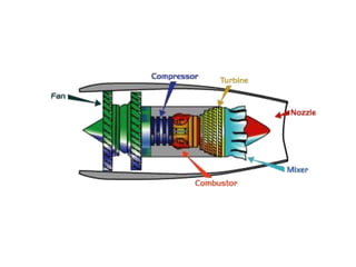
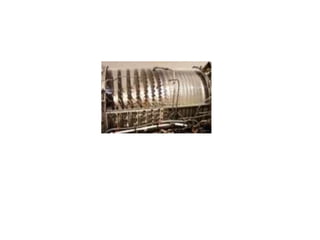
SlideShare a Scribd company logo
JET ENGINE
Contents
• History
• Types of Jet engines
• Major components
• Working
• Advanced Jet planes
History of Jet Engines
• Sir Isaac Newton in the 18th century was the first to theorize that
a rearward-channeled explosion could propel a machine forward at a great
rate of speed. This theory was based on his third law of motion.
As the hot air blasts backwards through the nozzle the plane moves forward.
• Henri Giffard built an airship which was powered by the first aircraft engine,
a three-horse power steam engine. It was very heavy, too heavy to fly.
• In 1874, Felix de Temple, built a monoplane that flew just a short hop
down a hill with the help of a coal fired steam engine.
• Otto Daimler in the late 1800's, invented the first gasoline engine.
• In 1903, the Wright Brothers flew, "The Flyer", with a 12 horse power
gas powered engine.
• From 1903, the year of the Wright Brothers first flight,
to the late 1930s the gas powered reciprocating internal-combustion engine
with a propeller was the sole means used to propel aircraft.
• It was Frank Whittle, a British pilot, who designed the first turbo jet engine
in 1930.The first Whittle engine successfully flew in April, 1937.
This engine featured a multistage compressor, and a combustion chamber,
a single stage turbine and a nozzle.
• The first jet airplane to successfully use this type of engine was the
German Heinkel He 178 invented by Hans Von Ohain.
It was the world's first turbojet powered flight.
The W2/700 engine flew in the
Gloster E.28/39, the first British
aircraft to fly with a turbojet
engine, and the Gloster Meteor.
A jet engine is an engine that
discharges a fast moving jet of fluid to
generate thrust in accordance with
Newton's third law of motion.
Types Of Jet engines
•Water Jets
•Motor Jets
•Turbo jets
•Turbo fans
•Rockets
•Ramjets
Working principle
Jet engines are also called as gas turbines. The
engine sucks air in at the front with a fan. A
compressor raises the pressure of the air. The
compressed air is then sprayed with fuel and an
electric spark lights the mixture. The burning gases
expand and blast out through the nozzle, at the
back of the engine. As the jets of gas shoot
backward, the engine and the aircraft are thrust
forward.
TURBO JET ENGINES
Major components
• Air intake
• Compressors
• Combustors
• Turbines
• Nozzles
• Fuel system
• Cooling system
Intermediate components
• Turbo pumps
• Afterburners( reheat)
• Thrust reversers
Fan-The fan is a first component in a turbo fan.
The large spinning fan sucks in large quantity of
air. Most of the fan blades are made up of titanium.
It then speeds this air up and splits it into two
parts. One part continues through the “core” or
center of the jet engine, where it is acted upon by
other jet engine components.
AIR INTAKE
The second part “bypasses” the core of the
jet engine. It goes through a duct which
surrounds the core to the back of jet engine
where it produces much of force that propels
the airplane forward. This cooler air helps to
quiet the jet engine as well as adding thrust
to the jet engine.
Compressor - The compressor is the first
component in the jet engine core.
The compressor is made up of fans with many
blades and attached to a shaft. The compressor
squeezes the air that enters it into progressively
smaller areas, resulting in an increase in the air
pressure. This results in an increase in the energy
potential of the air. The squashed air is forced into
the combustion chamber.
Combustor - In the combustor the air is mixed with fuel
and then ignited. There are as many as 20 nozzles
to spray fuel into the air stream. The mixture of air and
fuel catches fire. This provides a high temperature,
high-energy airflow. The fuel burns with the oxygen
in the compressed air, producing hot expanding gases.
The inside of the combustor is often made of ceramic
materials to provide a heat-resistant chamber.
The heat can reach 2700°.
Turbine - The high-energy airflow coming
out of the combustor goes into the turbine,
causing the turbine blades to rotate. The turbines
are linked by a shaft to turn the blades in the
compressor and to spin the intake fan at the front.
This rotation takes some energy from the high-energy
flow that is used to drive the fan and the compressor.
The gases produced in the combustion chamber move
through the turbine and spin its blades.
The turbines of the jet spin around thousands of
times. They are fixed on shafts which have
several sets of ball-bearing in between them.
Nozzle - The nozzle is the exhaust duct of the
jet engine. This is the jet engine part which actually
produces the thrust for the plane. The energy depleted
airflow that passed the turbine, in addition to the colder
air that bypassed the engine core, produces a force
when exiting the nozzle that acts to propel the engine,
and therefore the airplane, forward. The combination of
the hot air and cold air are expelled and produce an
exhaust, which causes a forward thrust.
The nozzle may be preceded by a mixer, which
combines the high temperature air coming from the jet
engine core with the lower temperature air that was
bypassed in the fan. The mixer helps to make the jet
engine quieter.
Variable Exhaust Nozzle,
on the GE F404-400 low-
bypass turbofan installed
on a Boeing F-18
Turbo pumps are centrifugal pumps which are spun
by gas turbines and are used to raise the propellant
pressure above the pressure in the combustion
chamber so that it can be injected and burnt.
Turbo pumps are very commonly used with rockets,
but ramjets and turbojets also have been known to use
them.
Turbopumps
Due to temperature limitations with the gas turbines,
jet engines do not consume all the oxygen in the air
('run stochiometric'). Afterburners burn the remaining
oxygen after exiting the turbines, but usually do so
inefficiently due to the low pressures existing at this
part of the jet engine; however this gains thrust, which
can be useful.
Afterburners (reheat)
Thrust reversal, also called reverse
thrust, is the temporary diversion of
an aircraft engine's exhaust or
changing of propeller pitch so that
the thrust produced is directed
forward, rather than aft. This acts
against the forward travel of the
aircraft, providing deceleration.
Thrust reversers
Apart from providing fuel to the engine,
the fuel system is also used to control
propeller speeds, compressor airflow
and cool lubrication oil. Fuel is usually
introduced by an atomized spray, the
amount of which is controlled
automatically depending on the rate of
airflow.
Feul system
. It also increases the energy extracted
by the turbine which drives the
compressor even faster and so there is
an increase in air flowing into the
engine as well.
Cooling air then passes through complex
passages within the turbine blades. After
removing heat from the blade material,
the air (now fairly hot) is vented, via
cooling holes, into the main gas stream.
Cover plates are incoperated on blades
Cooling system
This acts as a centrifugal compressor to
pressurize the cooling air before it enters
the blade. Another solution is to use an
ultra-efficient turbine rim seal to
pressurize the area where the cooling air
passes across to the rotating disc.
Jet engine
Jet engine
Jet engine
Jet engine

More Related Content

Similar to Jet engine

GAS TURBINE ENGINE ADLEY AND WAHYU.pptx
GAS TURBINE ENGINE ADLEY AND WAHYU.pptxGAS TURBINE ENGINE ADLEY AND WAHYU.pptx
GAS TURBINE ENGINE ADLEY AND WAHYU.pptx
Deyo4
 
gas turbine power plant
gas turbine power plantgas turbine power plant
gas turbine power plant
Dr. Ramesh B
 

Similar to Jet engine (20)

Jet Engine
Jet EngineJet Engine
Jet Engine
 
Gas Turbine Engines-Shenyang Aerospace University
Gas Turbine Engines-Shenyang Aerospace UniversityGas Turbine Engines-Shenyang Aerospace University
Gas Turbine Engines-Shenyang Aerospace University
 
PROJECT_GAS_TURBINE_ENGINE
PROJECT_GAS_TURBINE_ENGINEPROJECT_GAS_TURBINE_ENGINE
PROJECT_GAS_TURBINE_ENGINE
 
Turbojet
TurbojetTurbojet
Turbojet
 
Jet engines
Jet enginesJet engines
Jet engines
 
Seminar report on jet engine
Seminar report on jet engineSeminar report on jet engine
Seminar report on jet engine
 
UNIT - IV JET ENGINE PROPULSION
UNIT - IV JET ENGINE PROPULSIONUNIT - IV JET ENGINE PROPULSION
UNIT - IV JET ENGINE PROPULSION
 
JET ENGINE BASIC
JET ENGINE BASICJET ENGINE BASIC
JET ENGINE BASIC
 
Gas turbine and Jet Propulsion
Gas turbine and Jet PropulsionGas turbine and Jet Propulsion
Gas turbine and Jet Propulsion
 
Presentation.pptx
Presentation.pptxPresentation.pptx
Presentation.pptx
 
Jet engine
Jet engine Jet engine
Jet engine
 
GAS TURBINE ENGINE ADLEY AND WAHYU.pptx
GAS TURBINE ENGINE ADLEY AND WAHYU.pptxGAS TURBINE ENGINE ADLEY AND WAHYU.pptx
GAS TURBINE ENGINE ADLEY AND WAHYU.pptx
 
Gas turbine engine
Gas turbine engineGas turbine engine
Gas turbine engine
 
Jet engine working principle
Jet engine working principleJet engine working principle
Jet engine working principle
 
gas turbine power plant
gas turbine power plantgas turbine power plant
gas turbine power plant
 
Supercharger vs turbocharger
Supercharger vs turbochargerSupercharger vs turbocharger
Supercharger vs turbocharger
 
Ijmet 06 10_017
Ijmet 06 10_017Ijmet 06 10_017
Ijmet 06 10_017
 
A40076857 gas-turbine-engines
A40076857 gas-turbine-enginesA40076857 gas-turbine-engines
A40076857 gas-turbine-engines
 
Gas Tubine Working Principle.pdf
Gas Tubine Working Principle.pdfGas Tubine Working Principle.pdf
Gas Tubine Working Principle.pdf
 
Gas turbines
Gas turbinesGas turbines
Gas turbines
 

More from RAMESHCHANDRANE

More from RAMESHCHANDRANE (20)

e6ce0a4af2b3402b.pptx
e6ce0a4af2b3402b.pptxe6ce0a4af2b3402b.pptx
e6ce0a4af2b3402b.pptx
 
BELT CONVEYER.pptx
BELT CONVEYER.pptxBELT CONVEYER.pptx
BELT CONVEYER.pptx
 
Definition of management.pptx
Definition of management.pptxDefinition of management.pptx
Definition of management.pptx
 
Function of cam.pptx
Function of cam.pptxFunction of cam.pptx
Function of cam.pptx
 
presentationoncamanfollowers-130211063317-phpapp01 (1).pptx
presentationoncamanfollowers-130211063317-phpapp01 (1).pptxpresentationoncamanfollowers-130211063317-phpapp01 (1).pptx
presentationoncamanfollowers-130211063317-phpapp01 (1).pptx
 
2Dand3D transformationppt.pptx
2Dand3D transformationppt.pptx2Dand3D transformationppt.pptx
2Dand3D transformationppt.pptx
 
ABC Analysis ppt.pptx
ABC Analysis ppt.pptxABC Analysis ppt.pptx
ABC Analysis ppt.pptx
 
flexiblemanufacturingsystemfinal-140930090437-phpapp02 (1) (1).pptx
flexiblemanufacturingsystemfinal-140930090437-phpapp02 (1) (1).pptxflexiblemanufacturingsystemfinal-140930090437-phpapp02 (1) (1).pptx
flexiblemanufacturingsystemfinal-140930090437-phpapp02 (1) (1).pptx
 
dual fuel engine MANI.pptx
dual fuel engine MANI.pptxdual fuel engine MANI.pptx
dual fuel engine MANI.pptx
 
Management of the best foreign policymakers
Management of the best foreign policymakersManagement of the best foreign policymakers
Management of the best foreign policymakers
 
AIR SUSPENSION SEMINARY in the wayside you so much
AIR SUSPENSION SEMINARY in the wayside you so muchAIR SUSPENSION SEMINARY in the wayside you so much
AIR SUSPENSION SEMINARY in the wayside you so much
 
green engineering and technology admission
green engineering and technology admissiongreen engineering and technology admission
green engineering and technology admission
 
Carburettor.pdf
Carburettor.pdfCarburettor.pdf
Carburettor.pdf
 
jet engine.pdf
jet engine.pdfjet engine.pdf
jet engine.pdf
 
AUTONOMOUS CAR.pptx
AUTONOMOUS CAR.pptxAUTONOMOUS CAR.pptx
AUTONOMOUS CAR.pptx
 
Wheel Steering Syste.pdf
Wheel Steering Syste.pdfWheel Steering Syste.pdf
Wheel Steering Syste.pdf
 
SOLAR COOLING.ppt
SOLAR COOLING.pptSOLAR COOLING.ppt
SOLAR COOLING.ppt
 
History of Glass.ppt
History of Glass.pptHistory of Glass.ppt
History of Glass.ppt
 
WET SUMP LUBRICATION SYSTEM.ppt
WET SUMP LUBRICATION SYSTEM.pptWET SUMP LUBRICATION SYSTEM.ppt
WET SUMP LUBRICATION SYSTEM.ppt
 
SOLAR PANEL.pptx
SOLAR PANEL.pptxSOLAR PANEL.pptx
SOLAR PANEL.pptx
 

Recently uploaded

ONLINE VEHICLE RENTAL SYSTEM PROJECT REPORT.pdf
ONLINE VEHICLE RENTAL SYSTEM PROJECT REPORT.pdfONLINE VEHICLE RENTAL SYSTEM PROJECT REPORT.pdf
ONLINE VEHICLE RENTAL SYSTEM PROJECT REPORT.pdf
Kamal Acharya
 

Recently uploaded (20)

Natalia Rutkowska - BIM School Course in Kraków
Natalia Rutkowska - BIM School Course in KrakówNatalia Rutkowska - BIM School Course in Kraków
Natalia Rutkowska - BIM School Course in Kraków
 
Introduction to Machine Learning Unit-5 Notes for II-II Mechanical Engineering
Introduction to Machine Learning Unit-5 Notes for II-II Mechanical EngineeringIntroduction to Machine Learning Unit-5 Notes for II-II Mechanical Engineering
Introduction to Machine Learning Unit-5 Notes for II-II Mechanical Engineering
 
Halogenation process of chemical process industries
Halogenation process of chemical process industriesHalogenation process of chemical process industries
Halogenation process of chemical process industries
 
Pharmacy management system project report..pdf
Pharmacy management system project report..pdfPharmacy management system project report..pdf
Pharmacy management system project report..pdf
 
2024 DevOps Pro Europe - Growing at the edge
2024 DevOps Pro Europe - Growing at the edge2024 DevOps Pro Europe - Growing at the edge
2024 DevOps Pro Europe - Growing at the edge
 
Courier management system project report.pdf
Courier management system project report.pdfCourier management system project report.pdf
Courier management system project report.pdf
 
Cloud-Computing_CSE311_Computer-Networking CSE GUB BD - Shahidul.pptx
Cloud-Computing_CSE311_Computer-Networking CSE GUB BD - Shahidul.pptxCloud-Computing_CSE311_Computer-Networking CSE GUB BD - Shahidul.pptx
Cloud-Computing_CSE311_Computer-Networking CSE GUB BD - Shahidul.pptx
 
WATER CRISIS and its solutions-pptx 1234
WATER CRISIS and its solutions-pptx 1234WATER CRISIS and its solutions-pptx 1234
WATER CRISIS and its solutions-pptx 1234
 
fundamentals of drawing and isometric and orthographic projection
fundamentals of drawing and isometric and orthographic projectionfundamentals of drawing and isometric and orthographic projection
fundamentals of drawing and isometric and orthographic projection
 
Arduino based vehicle speed tracker project
Arduino based vehicle speed tracker projectArduino based vehicle speed tracker project
Arduino based vehicle speed tracker project
 
Toll tax management system project report..pdf
Toll tax management system project report..pdfToll tax management system project report..pdf
Toll tax management system project report..pdf
 
ONLINE VEHICLE RENTAL SYSTEM PROJECT REPORT.pdf
ONLINE VEHICLE RENTAL SYSTEM PROJECT REPORT.pdfONLINE VEHICLE RENTAL SYSTEM PROJECT REPORT.pdf
ONLINE VEHICLE RENTAL SYSTEM PROJECT REPORT.pdf
 
Scaling in conventional MOSFET for constant electric field and constant voltage
Scaling in conventional MOSFET for constant electric field and constant voltageScaling in conventional MOSFET for constant electric field and constant voltage
Scaling in conventional MOSFET for constant electric field and constant voltage
 
RESORT MANAGEMENT AND RESERVATION SYSTEM PROJECT REPORT.pdf
RESORT MANAGEMENT AND RESERVATION SYSTEM PROJECT REPORT.pdfRESORT MANAGEMENT AND RESERVATION SYSTEM PROJECT REPORT.pdf
RESORT MANAGEMENT AND RESERVATION SYSTEM PROJECT REPORT.pdf
 
Construction method of steel structure space frame .pptx
Construction method of steel structure space frame .pptxConstruction method of steel structure space frame .pptx
Construction method of steel structure space frame .pptx
 
Democratizing Fuzzing at Scale by Abhishek Arya
Democratizing Fuzzing at Scale by Abhishek AryaDemocratizing Fuzzing at Scale by Abhishek Arya
Democratizing Fuzzing at Scale by Abhishek Arya
 
Architectural Portfolio Sean Lockwood
Architectural Portfolio Sean LockwoodArchitectural Portfolio Sean Lockwood
Architectural Portfolio Sean Lockwood
 
ENERGY STORAGE DEVICES INTRODUCTION UNIT-I
ENERGY STORAGE DEVICES  INTRODUCTION UNIT-IENERGY STORAGE DEVICES  INTRODUCTION UNIT-I
ENERGY STORAGE DEVICES INTRODUCTION UNIT-I
 
Event Management System Vb Net Project Report.pdf
Event Management System Vb Net  Project Report.pdfEvent Management System Vb Net  Project Report.pdf
Event Management System Vb Net Project Report.pdf
 
Furniture showroom management system project.pdf
Furniture showroom management system project.pdfFurniture showroom management system project.pdf
Furniture showroom management system project.pdf
 

Jet engine

  • 2. Contents • History • Types of Jet engines • Major components • Working • Advanced Jet planes
  • 3. History of Jet Engines • Sir Isaac Newton in the 18th century was the first to theorize that a rearward-channeled explosion could propel a machine forward at a great rate of speed. This theory was based on his third law of motion. As the hot air blasts backwards through the nozzle the plane moves forward. • Henri Giffard built an airship which was powered by the first aircraft engine, a three-horse power steam engine. It was very heavy, too heavy to fly. • In 1874, Felix de Temple, built a monoplane that flew just a short hop down a hill with the help of a coal fired steam engine. • Otto Daimler in the late 1800's, invented the first gasoline engine.
  • 4. • In 1903, the Wright Brothers flew, "The Flyer", with a 12 horse power gas powered engine. • From 1903, the year of the Wright Brothers first flight, to the late 1930s the gas powered reciprocating internal-combustion engine with a propeller was the sole means used to propel aircraft. • It was Frank Whittle, a British pilot, who designed the first turbo jet engine in 1930.The first Whittle engine successfully flew in April, 1937. This engine featured a multistage compressor, and a combustion chamber, a single stage turbine and a nozzle. • The first jet airplane to successfully use this type of engine was the German Heinkel He 178 invented by Hans Von Ohain. It was the world's first turbojet powered flight.
  • 5. The W2/700 engine flew in the Gloster E.28/39, the first British aircraft to fly with a turbojet engine, and the Gloster Meteor.
  • 6.
  • 7.
  • 8.
  • 9. A jet engine is an engine that discharges a fast moving jet of fluid to generate thrust in accordance with Newton's third law of motion.
  • 10. Types Of Jet engines •Water Jets •Motor Jets •Turbo jets •Turbo fans •Rockets •Ramjets
  • 11. Working principle Jet engines are also called as gas turbines. The engine sucks air in at the front with a fan. A compressor raises the pressure of the air. The compressed air is then sprayed with fuel and an electric spark lights the mixture. The burning gases expand and blast out through the nozzle, at the back of the engine. As the jets of gas shoot backward, the engine and the aircraft are thrust forward. TURBO JET ENGINES
  • 12.
  • 13. Major components • Air intake • Compressors • Combustors • Turbines • Nozzles • Fuel system • Cooling system
  • 14. Intermediate components • Turbo pumps • Afterburners( reheat) • Thrust reversers
  • 15.
  • 16. Fan-The fan is a first component in a turbo fan. The large spinning fan sucks in large quantity of air. Most of the fan blades are made up of titanium. It then speeds this air up and splits it into two parts. One part continues through the “core” or center of the jet engine, where it is acted upon by other jet engine components. AIR INTAKE
  • 17. The second part “bypasses” the core of the jet engine. It goes through a duct which surrounds the core to the back of jet engine where it produces much of force that propels the airplane forward. This cooler air helps to quiet the jet engine as well as adding thrust to the jet engine.
  • 18.
  • 19. Compressor - The compressor is the first component in the jet engine core. The compressor is made up of fans with many blades and attached to a shaft. The compressor squeezes the air that enters it into progressively smaller areas, resulting in an increase in the air pressure. This results in an increase in the energy potential of the air. The squashed air is forced into the combustion chamber.
  • 20.
  • 21. Combustor - In the combustor the air is mixed with fuel and then ignited. There are as many as 20 nozzles to spray fuel into the air stream. The mixture of air and fuel catches fire. This provides a high temperature, high-energy airflow. The fuel burns with the oxygen in the compressed air, producing hot expanding gases. The inside of the combustor is often made of ceramic materials to provide a heat-resistant chamber. The heat can reach 2700°.
  • 22. Turbine - The high-energy airflow coming out of the combustor goes into the turbine, causing the turbine blades to rotate. The turbines are linked by a shaft to turn the blades in the compressor and to spin the intake fan at the front. This rotation takes some energy from the high-energy flow that is used to drive the fan and the compressor. The gases produced in the combustion chamber move through the turbine and spin its blades.
  • 23. The turbines of the jet spin around thousands of times. They are fixed on shafts which have several sets of ball-bearing in between them.
  • 24. Nozzle - The nozzle is the exhaust duct of the jet engine. This is the jet engine part which actually produces the thrust for the plane. The energy depleted airflow that passed the turbine, in addition to the colder air that bypassed the engine core, produces a force when exiting the nozzle that acts to propel the engine, and therefore the airplane, forward. The combination of the hot air and cold air are expelled and produce an exhaust, which causes a forward thrust.
  • 25. The nozzle may be preceded by a mixer, which combines the high temperature air coming from the jet engine core with the lower temperature air that was bypassed in the fan. The mixer helps to make the jet engine quieter.
  • 26. Variable Exhaust Nozzle, on the GE F404-400 low- bypass turbofan installed on a Boeing F-18
  • 27.
  • 28. Turbo pumps are centrifugal pumps which are spun by gas turbines and are used to raise the propellant pressure above the pressure in the combustion chamber so that it can be injected and burnt. Turbo pumps are very commonly used with rockets, but ramjets and turbojets also have been known to use them. Turbopumps
  • 29. Due to temperature limitations with the gas turbines, jet engines do not consume all the oxygen in the air ('run stochiometric'). Afterburners burn the remaining oxygen after exiting the turbines, but usually do so inefficiently due to the low pressures existing at this part of the jet engine; however this gains thrust, which can be useful. Afterburners (reheat)
  • 30. Thrust reversal, also called reverse thrust, is the temporary diversion of an aircraft engine's exhaust or changing of propeller pitch so that the thrust produced is directed forward, rather than aft. This acts against the forward travel of the aircraft, providing deceleration. Thrust reversers
  • 31.
  • 32.
  • 33. Apart from providing fuel to the engine, the fuel system is also used to control propeller speeds, compressor airflow and cool lubrication oil. Fuel is usually introduced by an atomized spray, the amount of which is controlled automatically depending on the rate of airflow. Feul system
  • 34. . It also increases the energy extracted by the turbine which drives the compressor even faster and so there is an increase in air flowing into the engine as well.
  • 35. Cooling air then passes through complex passages within the turbine blades. After removing heat from the blade material, the air (now fairly hot) is vented, via cooling holes, into the main gas stream. Cover plates are incoperated on blades Cooling system
  • 36. This acts as a centrifugal compressor to pressurize the cooling air before it enters the blade. Another solution is to use an ultra-efficient turbine rim seal to pressurize the area where the cooling air passes across to the rotating disc.