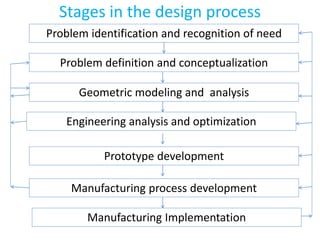
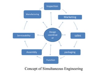
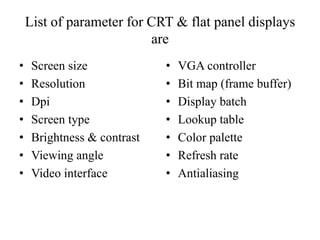
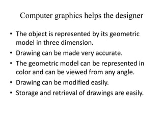
ME8691 - COMPUTER AIDED
DESIGN AND MANUFACTURING
UNIT 1
INTRODUCTION
SYLLABUS
 Product cycle
 Design process
 Sequential and concurrent engineering
 Computer aided design – CAD system architecture
 Computer graphics – co-ordinate systems- 2D and 3D
transformations - homogeneous coordinates
 Line drawing -Clipping- viewing transformation
SYLLABUS
 Brief introduction to CAD and CAM
 Manufacturing Planning, Manufacturing control
 CAD/CAM concepts
 Types of production
 Manufacturing models and Metrics
 Mathematical models of Production Performance
CAD
 CAD was introduced by Dr. Ivan Sutherland in 1963-1964
 CAD
1. Geometric Modeling
2. Design Engineering
3. Computer Graphics
 CAM
• 1. Network
• 2. Cad
• 3. Manufacturing
Product cycle
The cycle through which a product goes from
development to retirement is called product life
cycle.
The product cycle starts with developing the
product concept, evolving the design, engineering
the product, manufacturing the part, marketing
and servicing.
The product undergoes the following two main
processes
Design process
Manufacturing process
UNIT 1
FUNDAMENTALS OF COMPUTER
GRAPHICS
• Product cycle
• Design process
• Sequential and concurrent engineering
• Computer aided design – CAD system
architecture
• Computer graphics – co-ordinate systems- 2D and
3D transformations - homogeneous coordinates
• Line drawing -Clipping- viewing transformation
Design process
• Design is an activity that needs to be well organized
and should take into account all influences that are
likely to be responsible for the success of the product
under development.
Stages in the design process
Problem identification and recognition of need
Problem definition and conceptualization
Geometric modeling and analysis
Engineering analysis and optimization
Manufacturing process development
Prototype development
Manufacturing Implementation
Problem identification and recognition
of need
• Historical information
The current technology
Existing solution (even competitors product
details)
• General solution
This can be done by resorting to past designs,
engineering standards, technical reports,
catalogues, handbooks, patents etc.,
• Requirement specification
• Market force
Problem definition and
conceptualization
• Preliminary design
• Preliminary sketches
• Brainstorming
• Evaluation of the designs
Geometric modeling and analysis
• Geometric modeling
• Visualization
• Preliminary analysis
• Comparative analysis
Engineering analysis
• Strength analysis
• Kinematic analysis
• Dynamic analysis
• Heat/flow analysis
• Design for manufacture and assembly
Prototype development
• Rapid prototyping (RP)
– Testing and evaluation
– Design refinement
– Working drawing
Manufacturing process
development
• Process planning
• Tool design
• Manufacturing information generation
• Manufacturing simulation
• Information requirement design
• Time and motion study
• Production plant design
Computer assistance for design cycle
Problem identification and recognition of need
Problem definition and conceptualization
Geometric modeling and spatial analysis
Engineering analysis and optimization
Manufacturing process development
Prototype development
Manufacturing Implementation
Computer aided design
Finite Element analysis
Rapid prototyping
Computer aided
Manufacturing
CNC/Robots/CIM/ERP
Computer assisted
Operations
Serial (or) Sequential Engineering
• Sequential engineering is the process of marketing,
engineering design, planning, manufacturing,
quality, sales and service where each stage of the
development process is carried out separately, and
the next stage cannot start until the previous stage is
finished.
• This orderly step by step process will control to
complex projects but is very slow.
• Flow is only in one direction.
• Time consumption is more.
Serial or Sequential Engineering
Simultaneous (or) Concurrent
Engineering
• It deals with carrying out the design and
manufacturing activities at the same time (performing
tasks concurrently) while designing the product.
Inspection
Marketing
sales
packaging
Function
Assembly
Serviceability
Manufacturing
Design
coordinat
or
Concept of Simultaneous Engineering
Why Concurrent Engineering?
• Increasing product variety and technical
complexity.
• Increasing global competitive pressure.
• The need for rapid response to fast-changing
consumer demand.
• The need for shorter product life cycle.
• Lower manufacturing and production cost.
• Reduced defect rate and ultimately a faster
time to market.
COMPUTER AIDED DESIGN
• CAD utilizes the computer as a tool for all functions
that are involved in the design process.
• The main functions that would utilize the computer
are
– Layout design for the overall assembly
– Individual component modelling
– Assembly modelling
– Interference and tolerance stack checking
– Engineering drawing
Uses of CAD
• To create conceptual product model.
• Display the product in several colors to select color
combinations most appealing to customers.
• Rotate and view the object from various sides and
directions.
• Create and display all inner details of assembly.
• Check the interference or clearance between mating
parts in static or dynamic situations.
CAD technology provides the
engineer/designer the necessary help in
the following ways:
• CAD is a faster and more accurate than
conventional methods.
• It is useful of design work.
• You will never have to repeat the design or drawing
of any component.
• You can accurately calculate the various geometric
properties including dimensions of various
component.
• Modification of a model is very easy.
• Use of standard components makes for a very fast
The benefits of CAD in
manufacturing are
• Tool and fixture design
• Computer aided process planning
• Preparation of assembly lists and bill of materials
• Computer aided inspection
• Coding and classification of components
Application of CAD
• Printed circuit board
• Computer aided process planning
• Piping systems for process industries
• Finite element analysis
• Architecture – building design
CO ORDINATE SYSTEMS
• The right handed Cartesian coordinate system is
used for defining the geometry of the parts. In order
to specify the geometry of a given solid, it is
necessary to use a variety of coordinate systems.
• They are the following
– World Coordinate Systems
– User Coordinate systems
– Display Coordinates
– View Generation
World Coordinate Systems
• This refers to the actual coordinate system used as a
master for the component. Sometimes, it may also
be called the model coordinate system.
• In this chapter, we will call it the world coordinate
system (WCS). Figure shows a typical component,
which needs to be modelled.
• Another figure shows the component with its
associated world coordinate system, X,Y and Z.
User Coordinate Systems
• The default coordinate system when the user starts
the modelling is the WCS. However, sometimes it
becomes difficult to define certain geometries if
they are to be defined from the WCS.
• In such cases, alternate coordinate systems can be
defined relative to the WCS. These coordinate
systems are termed user coordinate systems (UCS)
or Working Coordinate systems.
• UCS reduces the modelling complexity.
DISPLAY COORDINATES
• This refers to the actual coordinates to be used for
displaying the image on the screen. It may also be
termed the screen coordinate system.
• The actual screen coordinates related to the pixels
to determine whether the actual values of the
screen or the virtual image that can be displayed
are needed to help in the image display.
VIEW GENERATION
• The display screen is two dimensional. Sometimes. It
is necessary to organize the information when
presented on the screen in two dimensions using the
orthogonal projection.
• The screen is therefore divided into a number of view
ports where in the various views are presented.
CAD SYSTEM ARCHITECTURE
• The CAD system comprise of the following
–Hardware
–Software
–Data
–Human knowledge and activities
The CAD elements are
• Model definition
• Model manipulation
• Picture generation
• User interaction
• Database management
• Utilities
COMPUTER GRAPHICS
• Computer graphics is defined as creation,
storage and manipulation of picture and
drawing by means of a digital computer.
• The user communicates data and commands to
the computer through a keyboard terminal and
the computer communicates with the user via a
Cathode Ray Tube (CRT)
Database
Component
model
Library data
Standards
Drawing
Working data
Geometry
Associated
data
Manufacturing
Applications
Database
management
Utilities
Picture
generation
Manipulator
Model
definition
Input
/
Outp
ut
users
DATA
FUNCTIONS
A typical hardware setup of a graphic system
keyboard
Floppy disk
drive (or) CD
I/O
(Interference/
Mass storage)
Microprocess
or
Video I/O TV Screen
System RAM
Memory
Data
Bus
Address
Bus
List of parameter for CRT & flat panel displays
are
• Screen size
• Resolution
• Dpi
• Screen type
• Brightness & contrast
• Viewing angle
• Video interface
• VGA controller
• Bit map (frame buffer)
• Display batch
• Lookup table
• Color palette
• Refresh rate
• Antialiasing
Computer graphics helps the designer
• The object is represented by its geometric
model in three dimension.
• Drawing can be made very accurate.
• The geometric model can be represented in
color and can be viewed from any angle.
• Drawing can be modified easily.
• Storage and retrieval of drawings are easily.

Unit 1 INTRODUCTION (COMPUTER AIDED DESIGN AND MANUFACTURING )

  • 1.
    ME8691 - COMPUTERAIDED DESIGN AND MANUFACTURING
  • 2.
  • 3.
    SYLLABUS  Product cycle Design process  Sequential and concurrent engineering  Computer aided design – CAD system architecture  Computer graphics – co-ordinate systems- 2D and 3D transformations - homogeneous coordinates  Line drawing -Clipping- viewing transformation
  • 4.
    SYLLABUS  Brief introductionto CAD and CAM  Manufacturing Planning, Manufacturing control  CAD/CAM concepts  Types of production  Manufacturing models and Metrics  Mathematical models of Production Performance
  • 5.
    CAD  CAD wasintroduced by Dr. Ivan Sutherland in 1963-1964  CAD 1. Geometric Modeling 2. Design Engineering 3. Computer Graphics  CAM • 1. Network • 2. Cad • 3. Manufacturing
  • 6.
    Product cycle The cyclethrough which a product goes from development to retirement is called product life cycle. The product cycle starts with developing the product concept, evolving the design, engineering the product, manufacturing the part, marketing and servicing. The product undergoes the following two main processes Design process Manufacturing process
  • 8.
    UNIT 1 FUNDAMENTALS OFCOMPUTER GRAPHICS • Product cycle • Design process • Sequential and concurrent engineering • Computer aided design – CAD system architecture • Computer graphics – co-ordinate systems- 2D and 3D transformations - homogeneous coordinates • Line drawing -Clipping- viewing transformation
  • 9.
    Design process • Designis an activity that needs to be well organized and should take into account all influences that are likely to be responsible for the success of the product under development.
  • 10.
    Stages in thedesign process Problem identification and recognition of need Problem definition and conceptualization Geometric modeling and analysis Engineering analysis and optimization Manufacturing process development Prototype development Manufacturing Implementation
  • 11.
    Problem identification andrecognition of need • Historical information The current technology Existing solution (even competitors product details) • General solution This can be done by resorting to past designs, engineering standards, technical reports, catalogues, handbooks, patents etc., • Requirement specification • Market force
  • 12.
    Problem definition and conceptualization •Preliminary design • Preliminary sketches • Brainstorming • Evaluation of the designs
  • 13.
    Geometric modeling andanalysis • Geometric modeling • Visualization • Preliminary analysis • Comparative analysis
  • 14.
    Engineering analysis • Strengthanalysis • Kinematic analysis • Dynamic analysis • Heat/flow analysis • Design for manufacture and assembly
  • 15.
    Prototype development • Rapidprototyping (RP) – Testing and evaluation – Design refinement – Working drawing
  • 16.
    Manufacturing process development • Processplanning • Tool design • Manufacturing information generation • Manufacturing simulation • Information requirement design • Time and motion study • Production plant design
  • 17.
    Computer assistance fordesign cycle Problem identification and recognition of need Problem definition and conceptualization Geometric modeling and spatial analysis Engineering analysis and optimization Manufacturing process development Prototype development Manufacturing Implementation Computer aided design Finite Element analysis Rapid prototyping Computer aided Manufacturing CNC/Robots/CIM/ERP Computer assisted Operations
  • 18.
    Serial (or) SequentialEngineering • Sequential engineering is the process of marketing, engineering design, planning, manufacturing, quality, sales and service where each stage of the development process is carried out separately, and the next stage cannot start until the previous stage is finished. • This orderly step by step process will control to complex projects but is very slow. • Flow is only in one direction. • Time consumption is more.
  • 19.
  • 20.
  • 21.
    Simultaneous (or) Concurrent Engineering •It deals with carrying out the design and manufacturing activities at the same time (performing tasks concurrently) while designing the product.
  • 22.
  • 23.
    Why Concurrent Engineering? •Increasing product variety and technical complexity. • Increasing global competitive pressure. • The need for rapid response to fast-changing consumer demand. • The need for shorter product life cycle. • Lower manufacturing and production cost. • Reduced defect rate and ultimately a faster time to market.
  • 24.
    COMPUTER AIDED DESIGN •CAD utilizes the computer as a tool for all functions that are involved in the design process. • The main functions that would utilize the computer are – Layout design for the overall assembly – Individual component modelling – Assembly modelling – Interference and tolerance stack checking – Engineering drawing
  • 25.
    Uses of CAD •To create conceptual product model. • Display the product in several colors to select color combinations most appealing to customers. • Rotate and view the object from various sides and directions. • Create and display all inner details of assembly. • Check the interference or clearance between mating parts in static or dynamic situations.
  • 26.
    CAD technology providesthe engineer/designer the necessary help in the following ways: • CAD is a faster and more accurate than conventional methods. • It is useful of design work. • You will never have to repeat the design or drawing of any component. • You can accurately calculate the various geometric properties including dimensions of various component. • Modification of a model is very easy. • Use of standard components makes for a very fast
  • 27.
    The benefits ofCAD in manufacturing are • Tool and fixture design • Computer aided process planning • Preparation of assembly lists and bill of materials • Computer aided inspection • Coding and classification of components
  • 28.
    Application of CAD •Printed circuit board • Computer aided process planning • Piping systems for process industries • Finite element analysis • Architecture – building design
  • 29.
    CO ORDINATE SYSTEMS •The right handed Cartesian coordinate system is used for defining the geometry of the parts. In order to specify the geometry of a given solid, it is necessary to use a variety of coordinate systems. • They are the following – World Coordinate Systems – User Coordinate systems – Display Coordinates – View Generation
  • 30.
    World Coordinate Systems •This refers to the actual coordinate system used as a master for the component. Sometimes, it may also be called the model coordinate system. • In this chapter, we will call it the world coordinate system (WCS). Figure shows a typical component, which needs to be modelled. • Another figure shows the component with its associated world coordinate system, X,Y and Z.
  • 32.
    User Coordinate Systems •The default coordinate system when the user starts the modelling is the WCS. However, sometimes it becomes difficult to define certain geometries if they are to be defined from the WCS. • In such cases, alternate coordinate systems can be defined relative to the WCS. These coordinate systems are termed user coordinate systems (UCS) or Working Coordinate systems. • UCS reduces the modelling complexity.
  • 34.
    DISPLAY COORDINATES • Thisrefers to the actual coordinates to be used for displaying the image on the screen. It may also be termed the screen coordinate system. • The actual screen coordinates related to the pixels to determine whether the actual values of the screen or the virtual image that can be displayed are needed to help in the image display.
  • 35.
    VIEW GENERATION • Thedisplay screen is two dimensional. Sometimes. It is necessary to organize the information when presented on the screen in two dimensions using the orthogonal projection. • The screen is therefore divided into a number of view ports where in the various views are presented.
  • 37.
    CAD SYSTEM ARCHITECTURE •The CAD system comprise of the following –Hardware –Software –Data –Human knowledge and activities
  • 38.
    The CAD elementsare • Model definition • Model manipulation • Picture generation • User interaction • Database management • Utilities
  • 39.
    COMPUTER GRAPHICS • Computergraphics is defined as creation, storage and manipulation of picture and drawing by means of a digital computer. • The user communicates data and commands to the computer through a keyboard terminal and the computer communicates with the user via a Cathode Ray Tube (CRT)
  • 40.
  • 41.
    A typical hardwaresetup of a graphic system keyboard Floppy disk drive (or) CD I/O (Interference/ Mass storage) Microprocess or Video I/O TV Screen System RAM Memory Data Bus Address Bus
  • 42.
    List of parameterfor CRT & flat panel displays are • Screen size • Resolution • Dpi • Screen type • Brightness & contrast • Viewing angle • Video interface • VGA controller • Bit map (frame buffer) • Display batch • Lookup table • Color palette • Refresh rate • Antialiasing
  • 43.
    Computer graphics helpsthe designer • The object is represented by its geometric model in three dimension. • Drawing can be made very accurate. • The geometric model can be represented in color and can be viewed from any angle. • Drawing can be modified easily. • Storage and retrieval of drawings are easily.