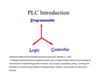
2. PLC Introduction
Controller
Programmable
Logic
Defined by National Electrical Manufacturers Association (NEMA) in 1978
“ A Digitally operating electronic apparatus which uses a programmable memory for the storage of
instructions for implementing specific functions, such as logic, sequencing, timing, counting and
arithmetic to control through Digital or Analogue Input / Outputs, various types of machines or
process
5. Advantages of PLC
Cost effective for controlling complex
systems.
Flexible and can be reapplied to control
other systems quickly and easily.
Computational abilities allow more
sophisticated control.
Trouble shooting aids make programming
easier and reduce downtime.
Reliable components make these likely to
operate for years before failure.
6. PLC APPLICATIONS
• Machine control
• Process control
• Automated product quality
inspection
• Data acquisition
• Material handling
• Sorters,packing lines, wrappers
7. Subsystems of a CNC system
Servo
HMI
MMI
PLC
(INTEGRATED)
PMC / PMI / PC
12. Role of a PLC
Part Program
Input devices
Output devices
•Digital
– Pushbuttons, limit switches
– Sensors, selectorswitches
•Analog devices
–Voltage or current inputs 0-100mA
and converts to digital information
–Flow meters,
–Pressure transducers,
–Thermocouples
Output Devices
• Digital devices
– Lights,leds, relay, small motors
• Analog devices
– Converts D to A
– 0-10V or 4-20mA
– Position control
– Flow control
– Pressure regulator
Part Program
O0110
N001 G90 ; Absolute coordinate system
N002 M06 T01 ; Select tool #1 (turning tool)
N003 M03 S2000 ; Turn spindle on (CW), set 2000 rpm
N004 G00 X0.0 Z-0.9 ; Rapid traverse
N005 G01 X0.0 Z-1.0 F10 ; enter part
N006 G01 X1.0 ; make facing cut
N007 G01 Z-3.9 ; turn side
N008 M30 ; end of program
18. FAST INPUTS
• CRITICAL INPUTS LIKE OVER TRAVEL LIMIT SWITCHES,
EMERGENCY STOP ARE FAST INPUTS TO PLC
• FAST INPUTS ARE GENERALLY CONNECTED WITH NC
CONTACTS
• TIME / INTERRUPT BASED SCANNING
25. Programming Languages
1. Ladder
2. Statement List
3. Flow Chart
4. HLL – High Level Language
IEC-1131-3 is the PLC programming Standard for Exchangeability
26. Ladder Programming
• Ladder is one of the powerful
ways of programming
• It is also known as Universal
Programming Language
• Standard for all PLCs from
different manufacturers
28. PROCEDURAL STEPS
1. Define the process
2. List out the sensors (Input & Output)
3. Assign the PLC I/O numbers
4. Build the logic’s
5. Key in the program into the PLC (Download if
program is developed in a Personal Computer)
6. Check the logic by forcing the inputs
7. Use I/O simulator and check the logic
8. Check the logic for various conditions of input
9. Make modifications if required and try again
29. Important points to remember during
Ladder Programming
• Logic is always executed from Left to Right and Top to Bottom.
The Input side of the Logic is executed first before executing
the Output side logic.
• All Internal Flags (Except Retentive Flags) are initialized to ‘0’
on power up.
• All Outputs are initialized to ‘0’ on power up.
• Output Flags can be used in the Input side, but not vice-versa.
• For a particular input either NO or NC symbol can be placed in
the Logic irrespective of the type of Contact used in Input.
• All logical sequences are generally a combination of AND, OR
and NOT logic’s only.
30. NOT GATE
The ladder logic equivalent for a NOT function looks like a
normal contact but with a slash through it.
Input A Output
0 1
1 0
The simplest of all logic functions is the NOT gate.
38. DIGITAL IO SPECS
• NO OF INPUTS : 8/16/32
• INPUT TYPE : SOURCING / SINKING
• INPUT VOLTAGE : 10-32VDC
• INPUT TURN ON LEVEL – 8VDC,@2.3mADC
MINIMUM
• INPUT TURN OFF LEVEL –
2.5VDC@0.05maADC MAXIMUM
• INPUT SOURCE : 5VDC FROM
CONTROLLER
40. Selection of PLCs
The points to be remembered while selecting PLC are as follows:
1. No. of Inputs / Outputs the PLC can handle
2. Type of Inputs / Outputs supported
3. No. of Timers / Counters available
4. Types of Counters / Timers available
5. Scan time per K of the PLC
6. PLC memory capacity
7. Fast / Interrupt Input and Power On scan
8. Proramming languages supported
9. Programming devices supported
10. Diagnostic features like Forcing function and Power Flow Diagram
11. Axes Control supported with PID algorithmn
12. Any Networking capability available
13. Special functions like Turret / ATC macros supported
14. Arithmetic / Boolean Instruction set
15. Isolation of Inputs / Outputs from PLC
16. Watch dog Timer