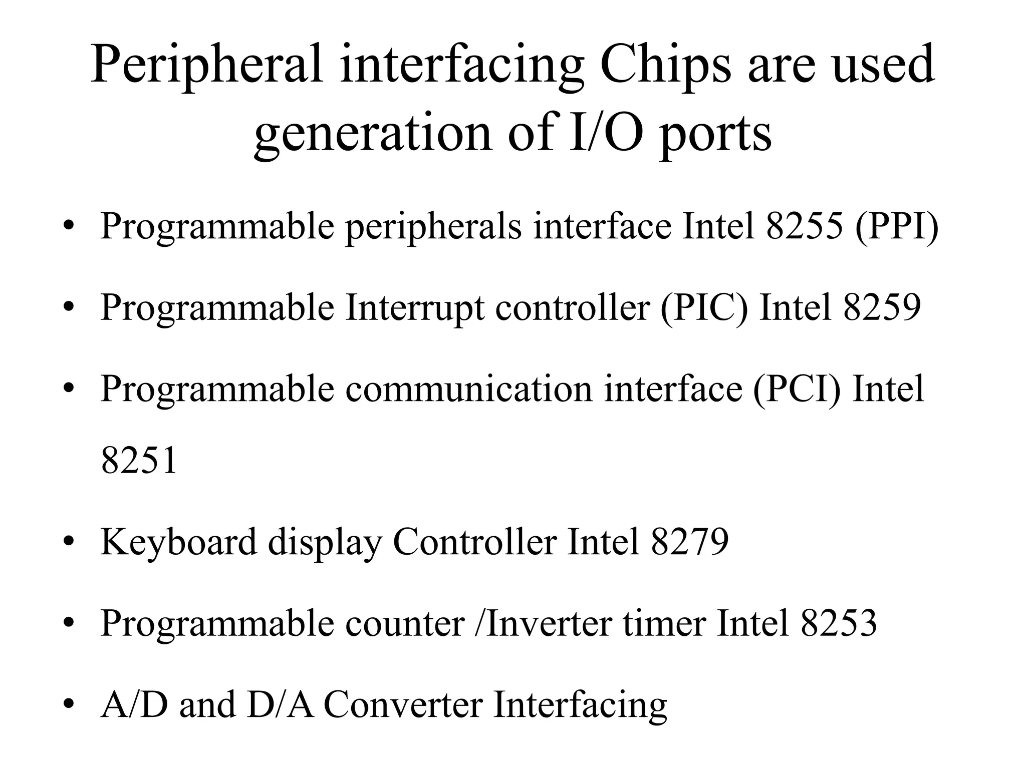
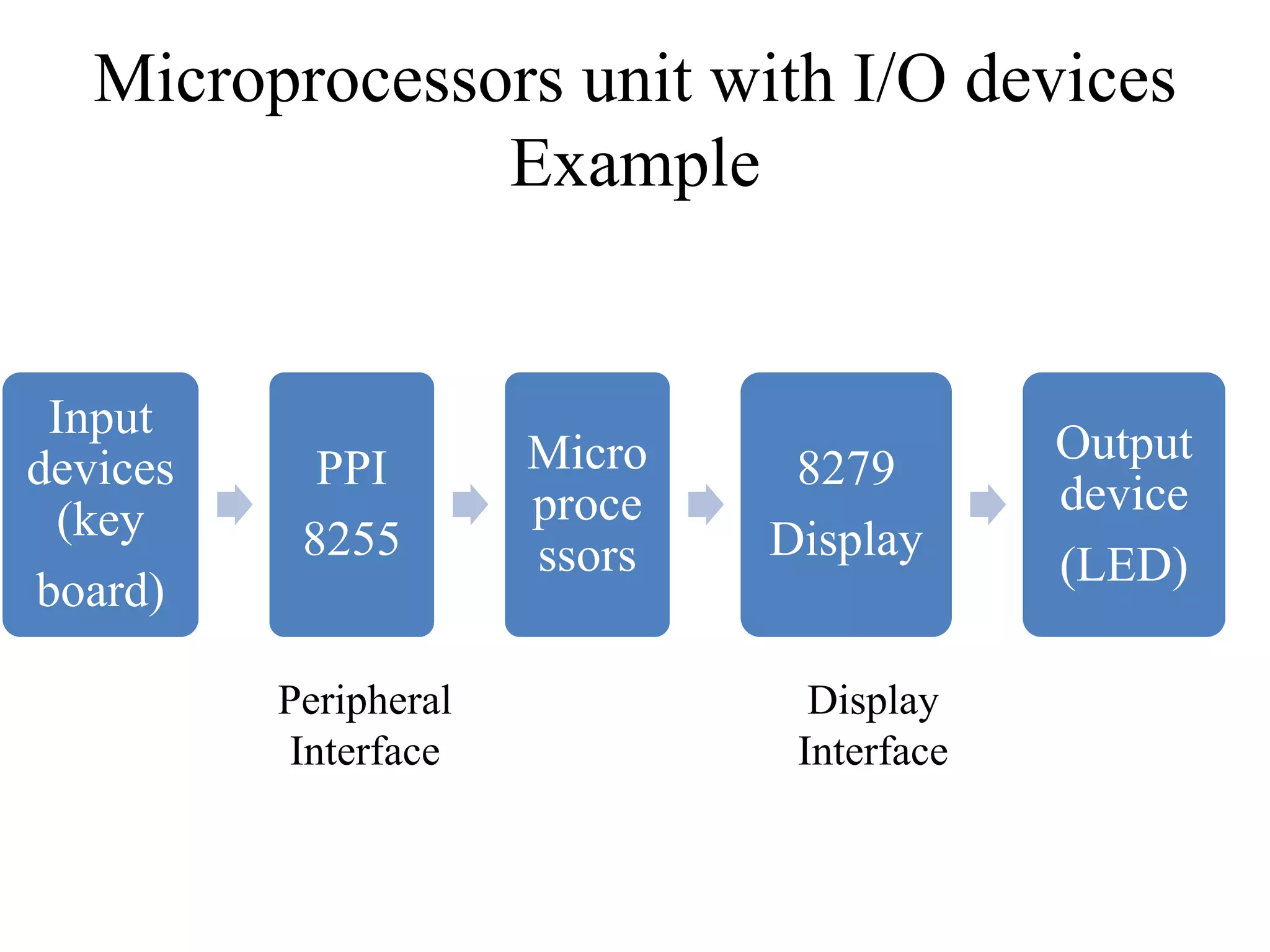
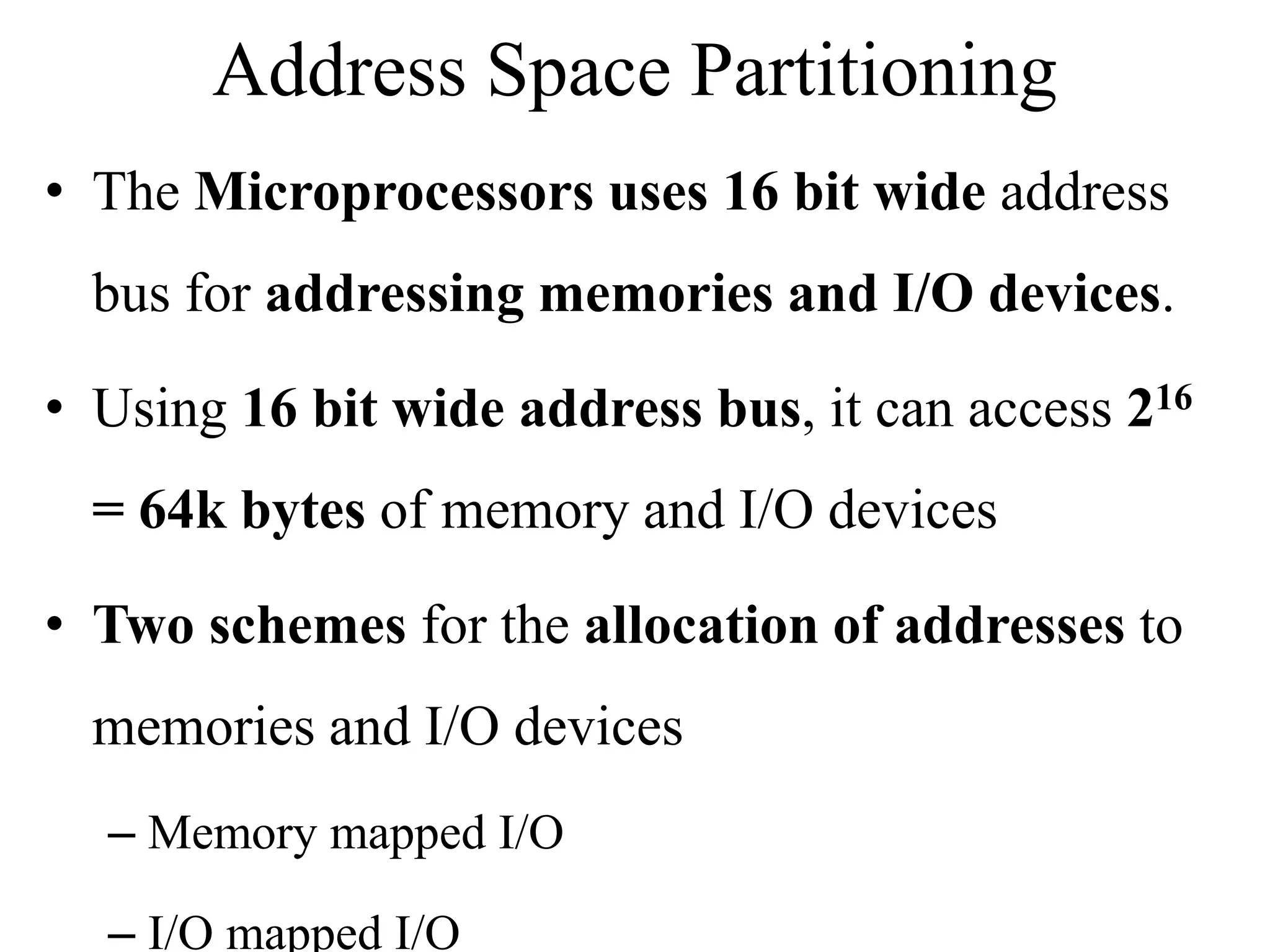
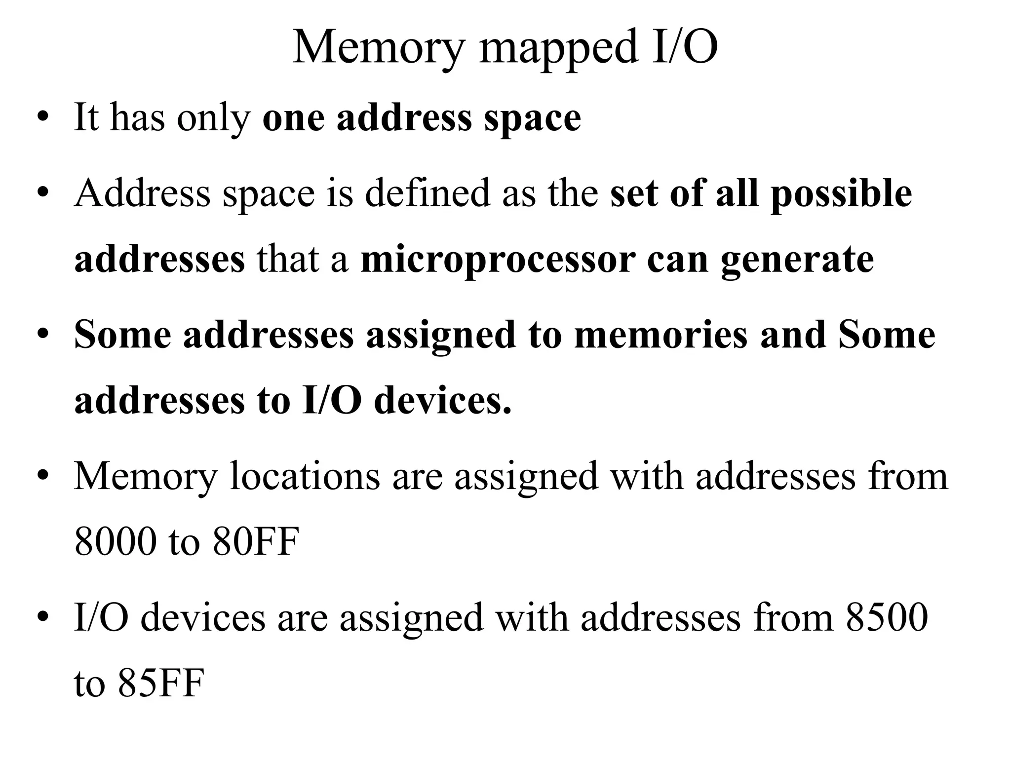
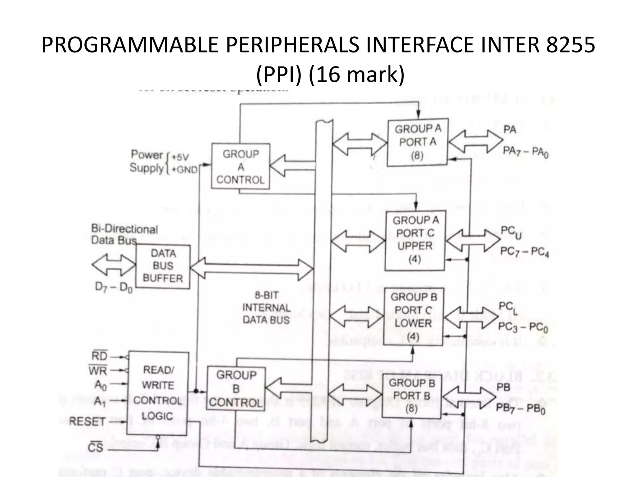
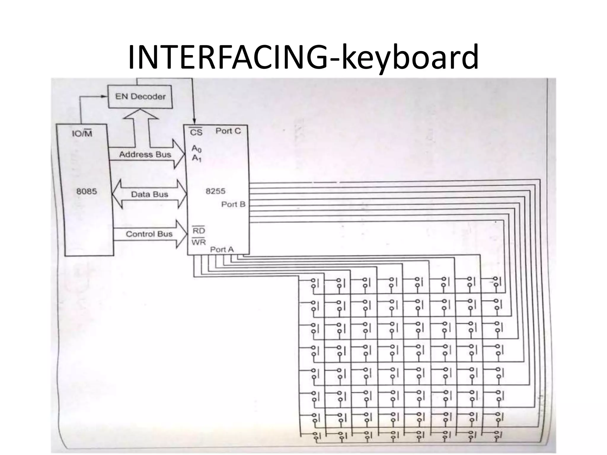
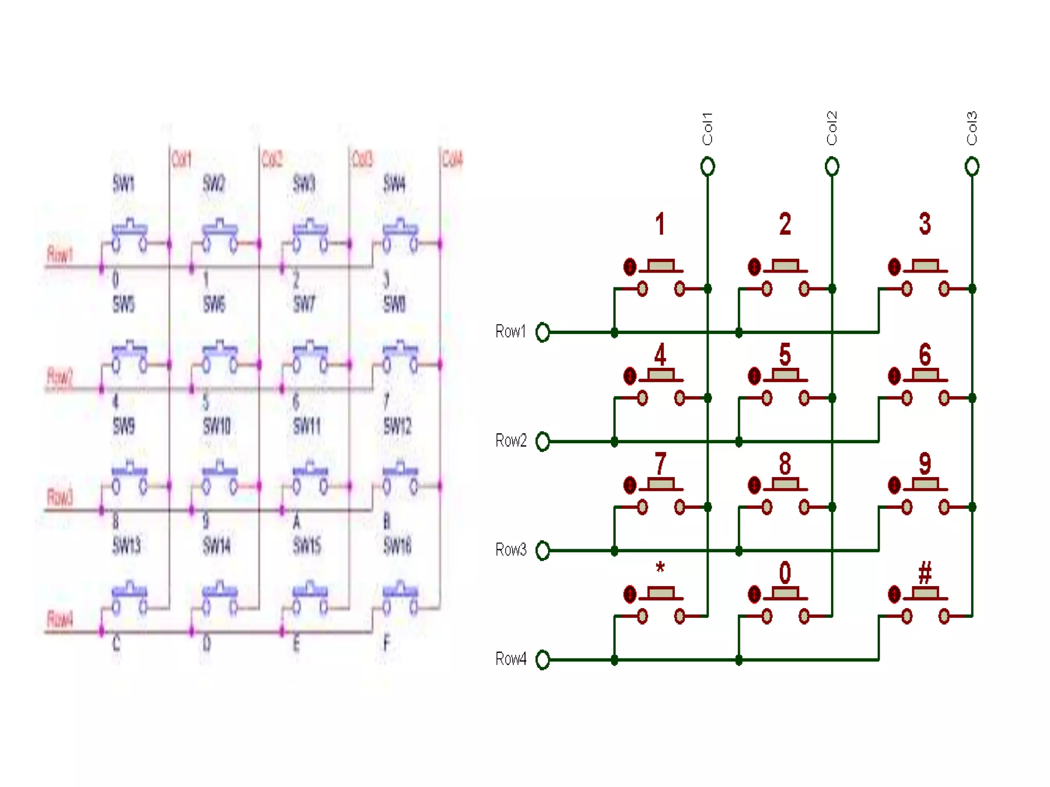
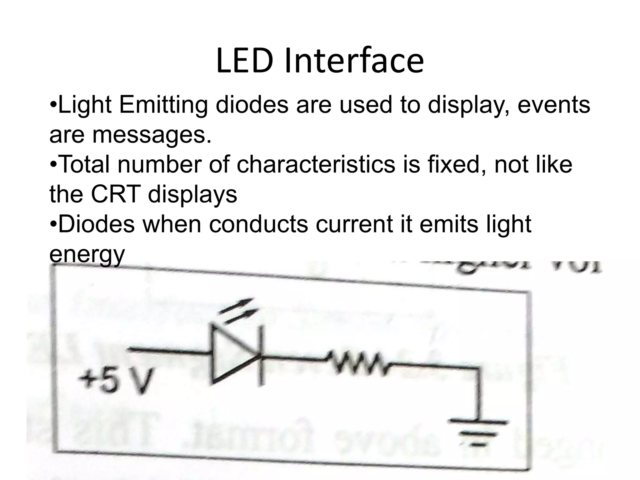
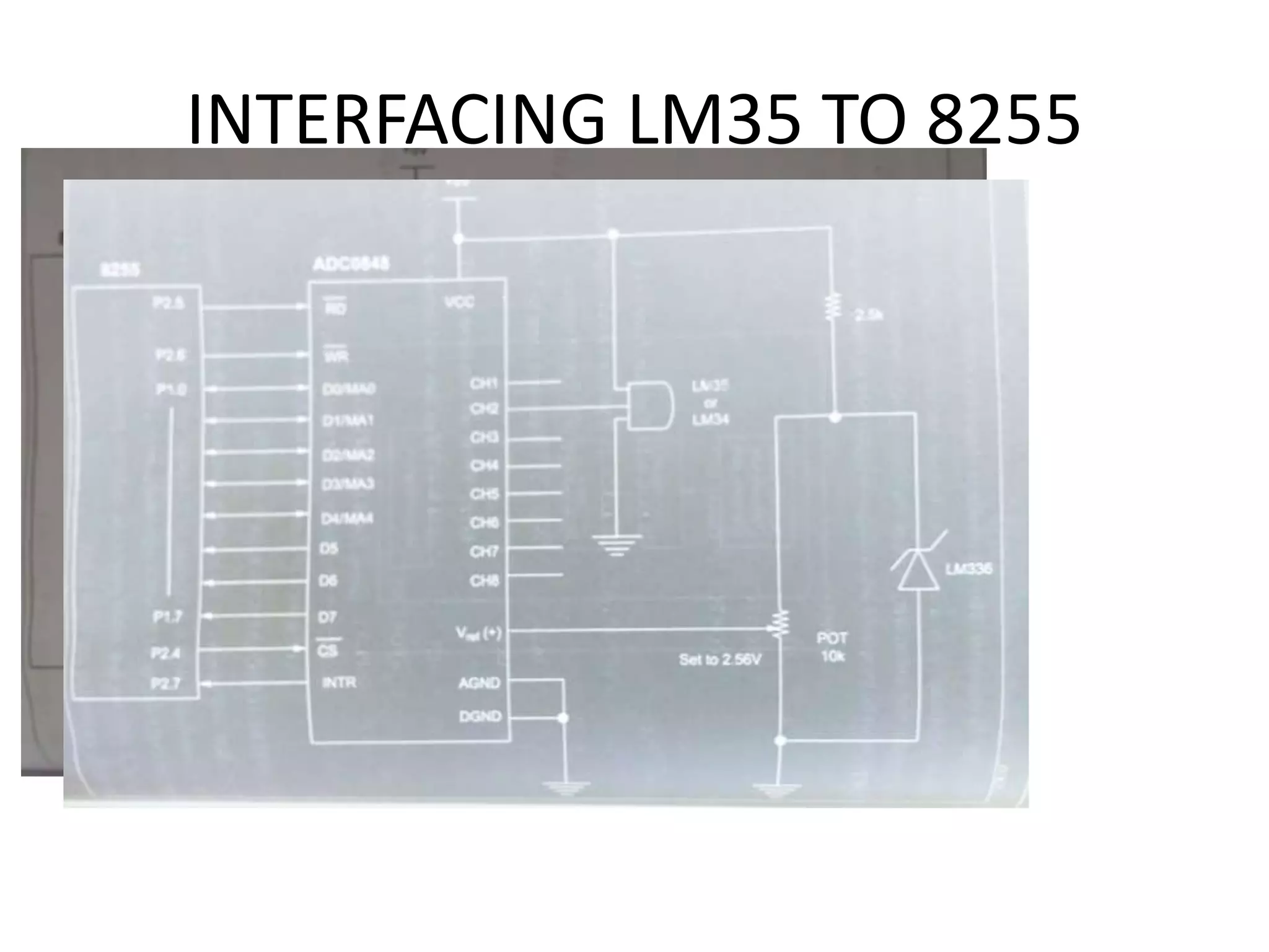
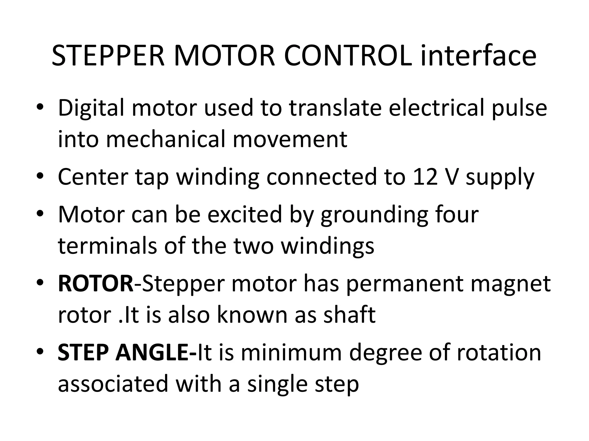
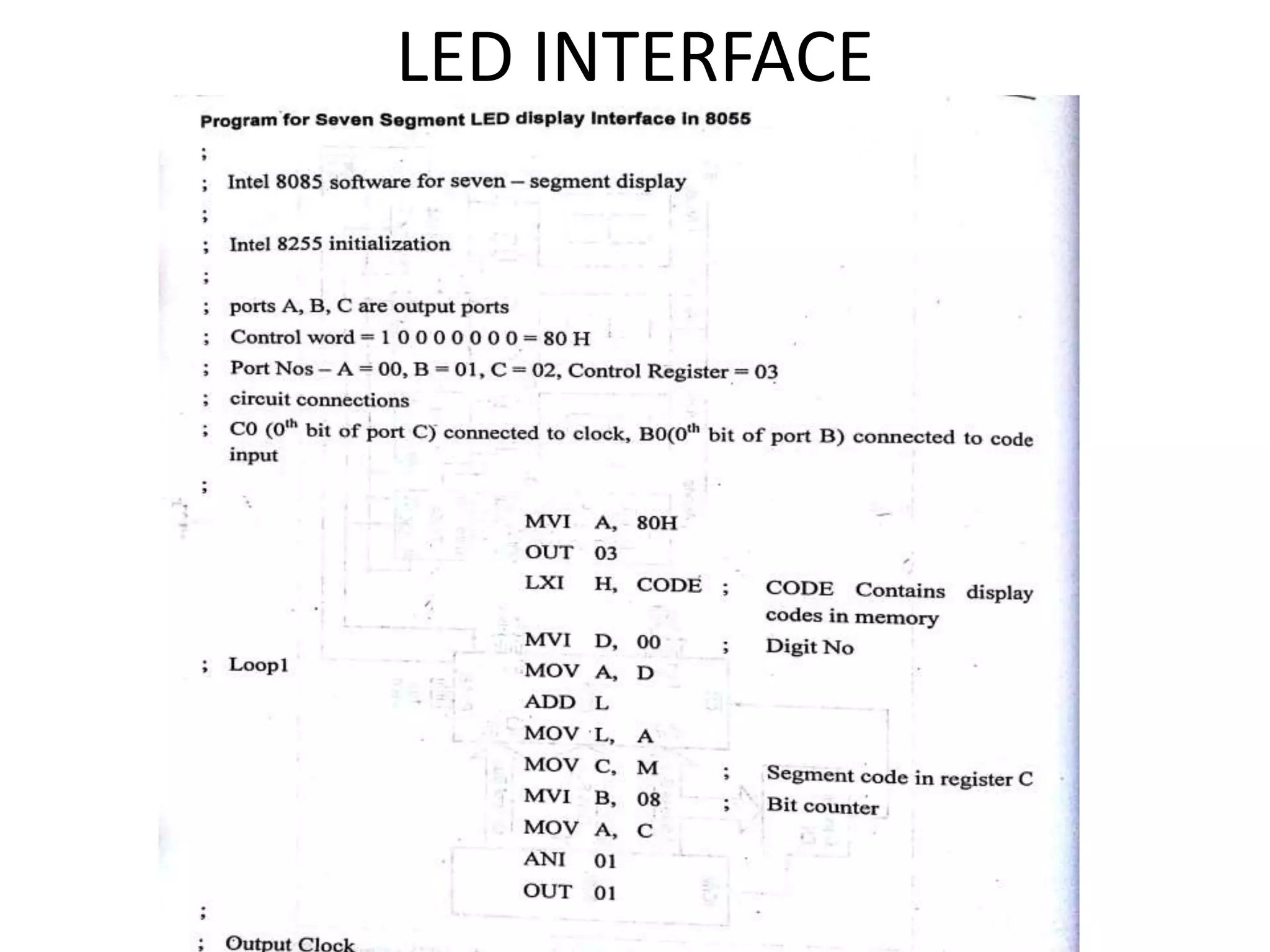
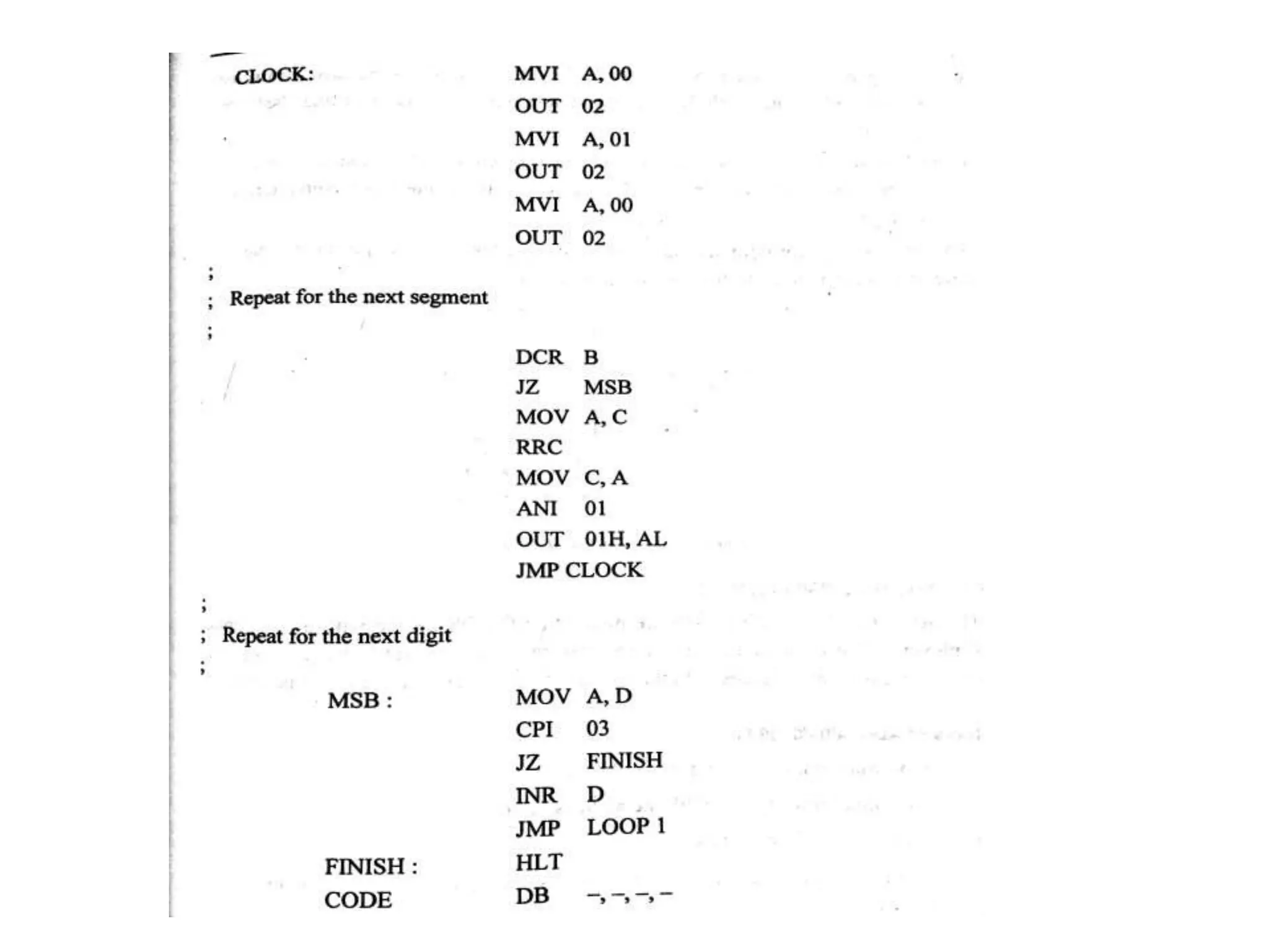
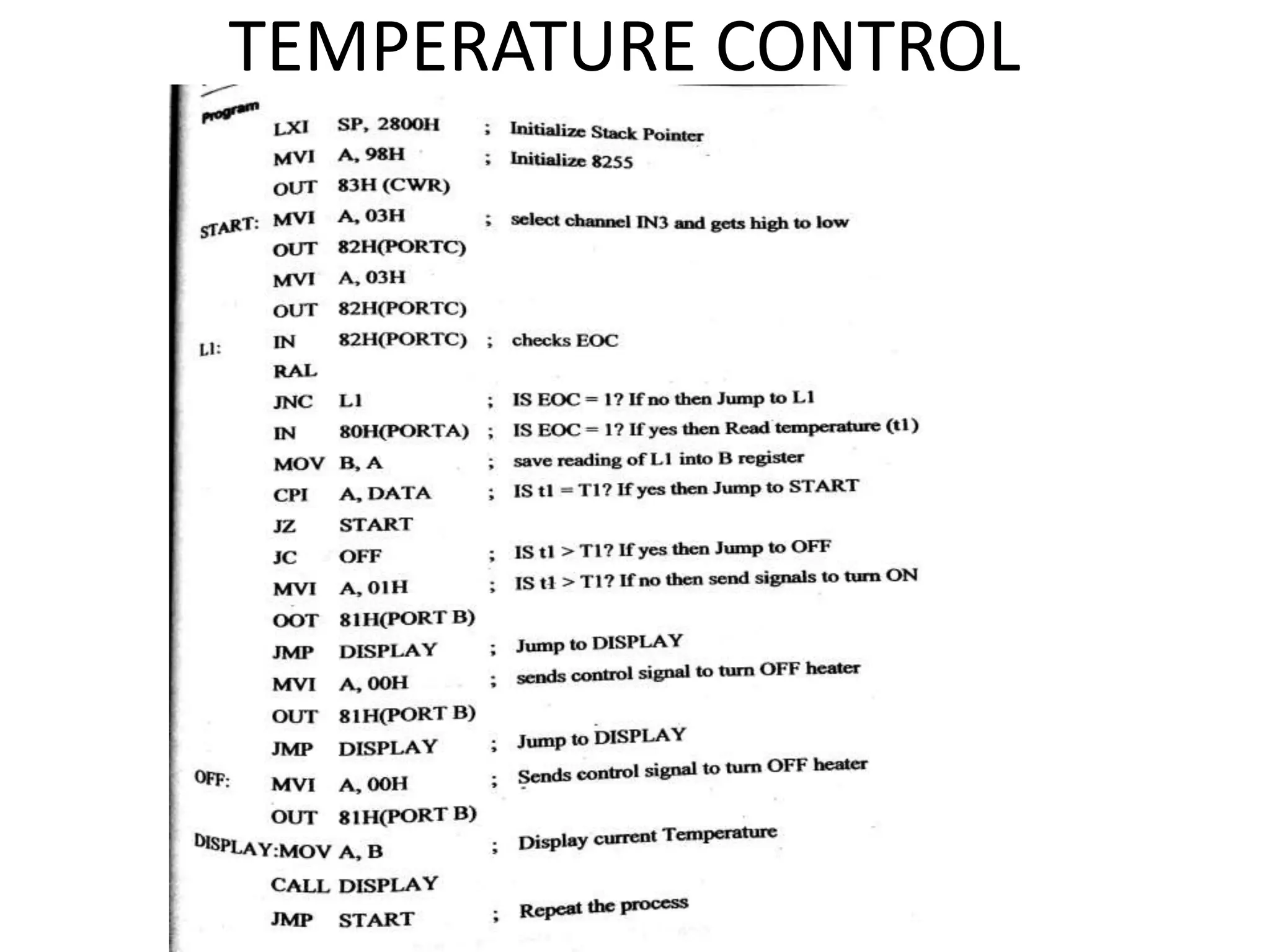
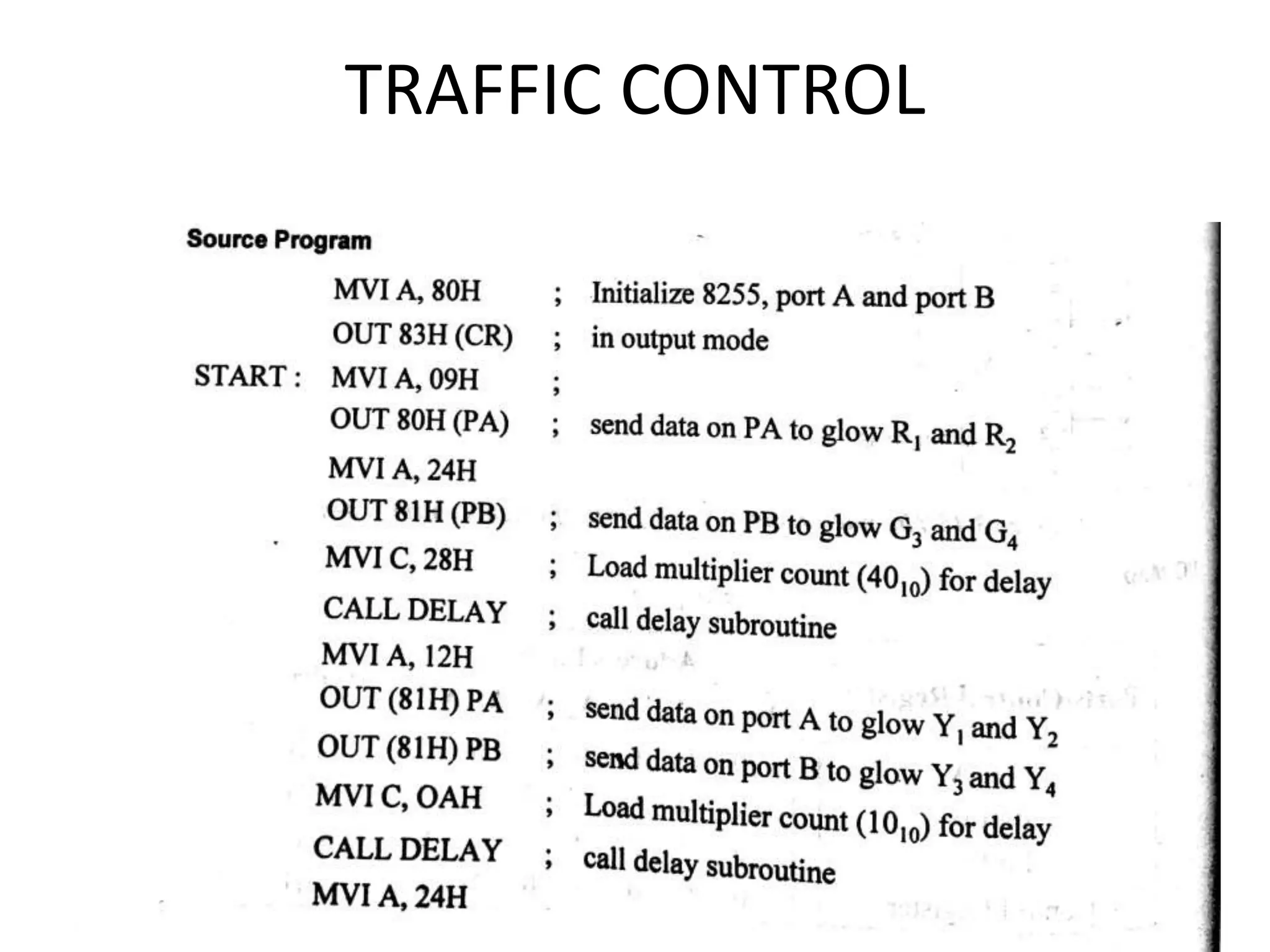
SlideShare a Scribd company logo
UNIT 3
PROGRAMMABLE PERIPERAL
INTERFACE
Content
• Introduction
• Architecture of 8255
• Keyboard interfacing
• LED display –interfacing
• ADC and DAC interface
• Temperature Control
• Stepper Motor Control
• Traffic Control interface
Introduction
• To communicate with the outside world,
microprocessor use peripherals (I/O devices)
• Input devices – Keyboards, A/D converters
etc.,
• Output devices – CRT, Printers, LEDs etc.,
• Peripherals are connected to the
microprocessors through electronic circuit
known as interfacing circuits.
Microprocessors unit with I/O devices
Input
devices
(keyboard)
Micro
processors
Output
devices
(LED)
Input
peripherals
Output
peripherals
• Each I/O device requires separate interfacing
circuit
• The circuit converts the data in input device in
to compitable format
• Output device converts o/p of microprocessor.
• Some of the interfacing devices are listed below:
– General purpose device
– Special purpose device
• Some of the general purpose interfacing devices
– I/O ports
– Programmable peripherals interface (PPI)
– D/A controllers
– Interrupt controller
• Some of the special purpose interfacing devices
– CRT controller
– Keyboard
– Display
– Floppy Disc controllers
Peripheral interfacing Chips are used
generation of I/O ports
• Programmable peripherals interface Intel 8255 (PPI)
• Programmable Interrupt controller (PIC) Intel 8259
• Programmable communication interface (PCI) Intel
8251
• Keyboard display Controller Intel 8279
• Programmable counter /Inverter timer Intel 8253
• A/D and D/A Converter Interfacing
Microprocessors unit with I/O devices
Example
Input
devices
(key
board)
PPI
8255
Micro
proce
ssors
8279
Display
Output
device
(LED)
Peripheral
Interface
Display
Interface
Address Space Partitioning
• The Microprocessors uses 16 bit wide address
bus for addressing memories and I/O devices.
• Using 16 bit wide address bus, it can access 216
= 64k bytes of memory and I/O devices
• Two schemes for the allocation of addresses to
memories and I/O devices
– Memory mapped I/O
– I/O mapped I/O
Memory mapped I/O
• It has only one address space
• Address space is defined as the set of all possible
addresses that a microprocessor can generate
• Some addresses assigned to memories and Some
addresses to I/O devices.
• Memory locations are assigned with addresses from
8000 to 80FF
• I/O devices are assigned with addresses from 8500
to 85FF
I/O mapped I/O scheme
• In this scheme, addresses assigned to
memories locations can also be assigned to
I/O devices
• Since the same address may be assigned to
memories locations or an I/O devices
• The microprocessor has a signal to distinguish
whether the address on the address bus is for
memories locations or an I/O devices
I/O mapped I/O scheme
• When signal is high, then address on the address bus is for an I/O
devices
• When signal is low, then address on the address bus is for
memory locations
• Two extra instruction IN and OUT are used to address I/O devices.
• The IN instruction is used to read the data of an input devices.
• The OUT instruction is used to send the data of an input devices.
• This scheme is suitable for a large system.
PROGRAMMABLE PERIPHERALS INTERFACE INTER 8255
(PPI) (16 mark)
• It is a multi port device.
• Ports can be programmed in variety ways
required by an operator.
• It is a general purpose programmable i/o devices
• It has 24 i/o pins 3*8 bit parallel ports.
• Port A, Port B, Port C,
• Port C can be groped in to two groups as 4 bits
FEATURES OF 8255
• 8255 is a widely used , programmable ,
parallel i/o devices
• It can easily transfer data under various
conditions
• Compatible with all micro processors
• Bit reset allows set reset of port C
• 8255 can operate 3 i/o modes
– Mode 0, Mode1 , mode 2
BLOCK DIAGRAM OF 8255
• It consists of Two 8 bit ports Port-a port – b, and
two 4 bit ports port C( upper and lower)
• GROUP-AAND GROUP –B CONTROLS:
– Group A control PC7-PC4
– Group B control PC3-PC0
• Port A 8 bit latched with three modes MODE
0,1,2
• Port B has 8 bit data input buffer mode 0,1
• Port C Port c 8 bit i/o buffer.
• DATA BUS BUFFER:
– Tri state bi directional buffer used to interface
internal bus data
– Read the data from the buffer/ write the data from
buffer
OPERATING MODE OF 8255
• Bit Set Reset (BSR) Mode
• I/O Mode
• BSR MODE:
– Reset the bits in port C
• I/O MODE :
– Mode 0- simple I/O ports
– Mode 1 – I/O ports with handshake
– Mode 2 – Bi directional I/O data transfer
BIT SET RESET (BSR) MODE
BSR control word format
I/O Mode
• Mode 0: Simple Input and Output
– Port A,B,C1 and C2 Each 8 bits
– Outputs are latched
– Ports do not have handshake
I/O Mode
• MODE 1: INPUT/ OUTPUT WITH
HANDSHAKE
– Input or output data transfer controlled by handshaking
signals
– Hand shaking speed and data transfer speeds are not
same (Ex: printer and system data transfer speed)
– Ports A and B are designed to operate port C
– Port a And Port B are programmed at mode 1
– PINS ARE
• PORT A - PC3, PC4, PC5 output port
• PORT C –PC6, PC7 i/p or o/p
• Port A in Mode 1- Port B is operated in MODE 0
I/O Mode
• D0-D7 data bus
– bi directional, tri state data bus line
– It is used to transfer data and control word from 8085
to 8255
• RD (Read)
– When this pin is low, the CPU can read data in the
port or status word through the data buffer
• WR (write)
– When this pin is high, the CPU can write data in
the port or in the control register through the data
buffer
Mode2
• Mode 2 – Bi-directional I/O
• Port A can be programmed to operate as a
bidirectional operation.
• The mode 2 operation is only for port A
• When port A is programmed in Mode 2, the Port B
can be used in either Mode 1 or Mode 0.
• Mode 2 operation the port a is controlled by PC3 to
PC7 of port C.
PIN
DIAGRAM
OF 8255
• RESET:
– High input is used to reset 8255.
– Reset input is high control register is cleared
– Reset signal from 8085 is used to reset 8255
• A0 and A1
– Input signals with RD and WR status
• PA0-PA7 (port –a)
– 8 bit bi-directional I/O pins datas send data to output
device and receive data to input device
• PB0-PB7 (Port –B)
– I/O pins datas send data to output device and receive
data to input device
PROGRAMMING and
OPERATION of 8255
I) Programming in MODE 0
• A,B,C configured as input and output ports.
• D7 –set to 1
• D6,D5,D2- all set to 0 –MODE 0
• D4,D3,D1 and D0- determine weather the
corresponding ports are to configured as
input or output
A B GROUP A GROUP B
D4 D3 D1 D0 PORT A PORTC U PORT B PORT C L
0 0 0 0 OUT OUT OUT OUT
0 0 0 1 OUT OUT OUT IP
0 0 1 0 OUT OUT IP OUT
0 0 1 1 OUT OUT IP IP
0 1 0 0 OUT IP OUT OUT
0 1 0 1 OUT IP OUT IP
0 1 1 0 OUT IP IP OUT
0 1 1 1 OUT IP IP IP
1 0 0 0 IP OUT OUT OUT
1 0 0 1 IP OUT OUT IP
1 0 1 0 IP OUT IP OUT
1 0 1 1 IP OUT IP IP
1 1 0 0 IP IP OUT OUT
1 1 0 1 IP IP OUT IP
1 1 1 0 IP IP IP OUT
1 1 1 1 IP IP IP IP
• INPUT MODE
– After initializing the 8255 input mode 0
– CPU can read through initiate the read command (
example PENDRIVE)
– READ command activates RD signal
• OUTPUT MODE:
– After initializing the output mode 0
– CPU can write data in initiating command with
proper port address.
Programming in MODE 1
• IBF- input buffer full
• INTR- interrupt request
• INTE-interrupt enable
• OBF-output buffer full
• INTR-interrupt request
• INTE-interrupt enable
• OUTPUT BUFFER FULL
– Output signal goes low when microprocessor unit
writes data in the output latch 8255
– 8255 receives acknowledgement to that peripheral
• ACK (acknowledgement)
– Input peripheral has low output pheripheral devices
has receive data
• INTR AND INTE
– Interrupt request
– Interrupt enable
Programming in MODE 2
Bi-directional bus
MODE 2 CONFIGURATION
• INPUT CONTROL SIGNAL:
– STB(strobe input)
• Low input signal enables PORT A
– IBF(input buffer full)
• High input devices indicates loaded loaded on port a
– INTE(interrupt request)
• Interrupt enable with input buffer full.
• OUTPUT CONTROL SIGNAL:
– OBF
• Low output indicates cpu written data in port a
– ACK
• Low input signal enables output buffer of port A
Keyboard Interfacing & Interfacing
cable
• Keyboard consists of number of switches for
entering datas
• First of all location of key must be determined
• Now we consider four keys
•We can interface connecting with all the
inputs together for high signals
•For example 64 key required 8-bit ports
2 X 2 Key operation
Keyboard Microprocessor Interface software Flowchart
INTERFACING-keyboard
LED Interface
•Light Emitting diodes are used to display, events
are messages.
•Total number of characteristics is fixed, not like
the CRT displays
•Diodes when conducts current it emits light
energy
•The LED’S interface with microprocessor through an
output port
Microprocessor interface to LED
(Common anode)
•In Common CATHODE configuration whenever
the bit is 1 corresponding LED is glow
•In common ANODE configuration 0 in any bit
position LED will glow.
SEVEN SEGMENT LED
0-WILL GLOW
1-DON’T GLOW
Microprocessor interface to 7 segment LED
(Parallel)
•The ANODES of all LED’s held permanently at +5V, to over
come these draw back serial port
Microprocessor interface to 7
segment LED (serial)
Serial interface of 7
segment LED to
Microprocessor
software flowchart
INTERFACE-LED display
ANALOG TO DIGITAL CONVERTER
• The A/D conversion is a quantizing process an
analog signal in to equivalent binary word.
• ADC family
– The ADC 0808 and 0809 are monolithic CMOS
device with an 8 channel multiplexer
– These devices are designed to operate from the
command to micro processor control bussed with
the tristate latches driving the data bus.
ADC INTERFACE
BLOCK diagram of ADC 0808
PIN diagram of ADC 0808
DAC INTERFACE
Pin diagram of DAC
Pin diagram of DAC
INTERFACING diagram for DAC
TEMPERATURE CONTROL
• Transducer convert physical data into electrical
signal
• Physical data –temp, light, flow, speed etc…
• Depending on the transducer can produce output
such as, VOLTAGE, CURRENT, RESISTANCE.
• Temperature sensor –convert temperature to
electrical signal by thermister.
• LM34 & LM35 –temperature sensor series from
NATIONAL SEMICONDUCTOR CO-
OPERATION
• LM34
• Output voltage is
linearly proportional to
Fahrenheit temp
• No external calibration
• 10mV for each degree
of Fahrenheit temp
• LM35
• Output voltage is
linearly proportional to
Celsius temp
• No external calibration
• 10mV for each degree
of Centigrate temp
INTERFACING LM35 TO 8255
STEPPER MOTOR CONTROL interface
• Digital motor used to translate electrical pulse
into mechanical movement
• Center tap winding connected to 12 V supply
• Motor can be excited by grounding four
terminals of the two windings
• ROTOR-Stepper motor has permanent magnet
rotor .It is also known as shaft
• STEP ANGLE-It is minimum degree of rotation
associated with a single step
• The given excitation sequence rotates motor in
clockwise direction
• Excitation sequence changes due to winding
connections
• The table give step excitation sequence
• Each step of the motor is 0.9 degree
Excitation Table
Step X1 X2 X3 X4
1 0 1 0 1
2 1 0 0 1
3 1 0 1 0
4 0 1 1 0
1 0 1 0 1
Stepper Motor Interface
Traffic Light Control System
• Allow traffic from W to E and E to W transition
for 20 seconds
• Give transition period of 5 seconds (yellow
bulbs ON)
• Allow traffic from N to s and S to n for 20
seconds
• Give transition period of 5 seconds (yellow
bulbs ON)
• Repeat the process
Interfacing diagram for Traffic Light
Control System
Traffic Light Control System
LED INTERFACE
TEMPERATURE CONTROL
STEPPER MOTOR
TRAFFIC CONTROL
MECHATRONICS-Unit 3-PROGRAMMABLE PERIPERAL INTERFACE.ppt

More Related Content

Similar to MECHATRONICS-Unit 3-PROGRAMMABLE PERIPERAL INTERFACE.ppt

MicroProcessors and MicroControllersUnit3
MicroProcessors and MicroControllersUnit3MicroProcessors and MicroControllersUnit3
MicroProcessors and MicroControllersUnit3
deepakdmaat
 
8255.pdf
8255.pdf8255.pdf
8255.pdf
someshdash1
 
Programmable Peripheral Devices
Programmable Peripheral Devices Programmable Peripheral Devices
Programmable Peripheral Devices
glorypriyadharshini1
 
8255 PPI
8255 PPI8255 PPI
8255 PPI
deval patel
 
Mod-2 M&M.pptx
Mod-2 M&M.pptxMod-2 M&M.pptx
Mod-2 M&M.pptx
TechCook1
 
8255 PPI.pptx
8255 PPI.pptx8255 PPI.pptx
8255 PPI.pptx
ssuser823c58
 
8255 & IO Interfacing.pdf
8255 & IO Interfacing.pdf8255 & IO Interfacing.pdf
8255 & IO Interfacing.pdf
Ilavarasan Tamizh
 
8255-PPI MPMC text book for engineering.ppt
8255-PPI MPMC text book for engineering.ppt8255-PPI MPMC text book for engineering.ppt
8255-PPI MPMC text book for engineering.ppt
khushiduppala
 
Micro Processor And Micro Controller for engineering in Pondicherry University
Micro Processor And Micro Controller for engineering in Pondicherry UniversityMicro Processor And Micro Controller for engineering in Pondicherry University
Micro Processor And Micro Controller for engineering in Pondicherry University
ShyamShyam76
 
8255 Programmable parallel I/O
8255 Programmable parallel I/O 8255 Programmable parallel I/O
8255 Programmable parallel I/O
Muhammed Afsal Villan
 
UNIT 4 8051Microcontroller.pptx
UNIT 4 8051Microcontroller.pptxUNIT 4 8051Microcontroller.pptx
UNIT 4 8051Microcontroller.pptx
Gowrishankar C
 
Embedded system design using arduino
Embedded system design using arduinoEmbedded system design using arduino
Embedded system design using arduino
Santosh Verma
 
knowledge in daily life.ppt
knowledge in daily life.pptknowledge in daily life.ppt
knowledge in daily life.ppt
SunilSharma941036
 
Unit 3 mpmc
Unit 3 mpmcUnit 3 mpmc
Unit 3 mpmc
tamilnesaner
 
8255 ppi.pptx
8255 ppi.pptx8255 ppi.pptx
8255 ppi.pptx
zahid235639
 
Unit-IV.pptx
Unit-IV.pptxUnit-IV.pptx
Unit-IV.pptx
ssuser47c811
 
Microprocessor and Application (8085)
Microprocessor and Application (8085)Microprocessor and Application (8085)
Microprocessor and Application (8085)ufaq kk
 
MPMC
MPMC MPMC

Similar to MECHATRONICS-Unit 3-PROGRAMMABLE PERIPERAL INTERFACE.ppt (20)

MicroProcessors and MicroControllersUnit3
MicroProcessors and MicroControllersUnit3MicroProcessors and MicroControllersUnit3
MicroProcessors and MicroControllersUnit3
 
8255.pdf
8255.pdf8255.pdf
8255.pdf
 
Programmable Peripheral Devices
Programmable Peripheral Devices Programmable Peripheral Devices
Programmable Peripheral Devices
 
8255 PPI
8255 PPI8255 PPI
8255 PPI
 
Mod-2 M&M.pptx
Mod-2 M&M.pptxMod-2 M&M.pptx
Mod-2 M&M.pptx
 
8255 PPI.pptx
8255 PPI.pptx8255 PPI.pptx
8255 PPI.pptx
 
8255 & IO Interfacing.pdf
8255 & IO Interfacing.pdf8255 & IO Interfacing.pdf
8255 & IO Interfacing.pdf
 
8255-PPI MPMC text book for engineering.ppt
8255-PPI MPMC text book for engineering.ppt8255-PPI MPMC text book for engineering.ppt
8255-PPI MPMC text book for engineering.ppt
 
7 8255
7 82557 8255
7 8255
 
Micro Processor And Micro Controller for engineering in Pondicherry University
Micro Processor And Micro Controller for engineering in Pondicherry UniversityMicro Processor And Micro Controller for engineering in Pondicherry University
Micro Processor And Micro Controller for engineering in Pondicherry University
 
8255 Programmable parallel I/O
8255 Programmable parallel I/O 8255 Programmable parallel I/O
8255 Programmable parallel I/O
 
UNIT 4 8051Microcontroller.pptx
UNIT 4 8051Microcontroller.pptxUNIT 4 8051Microcontroller.pptx
UNIT 4 8051Microcontroller.pptx
 
Embedded system design using arduino
Embedded system design using arduinoEmbedded system design using arduino
Embedded system design using arduino
 
knowledge in daily life.ppt
knowledge in daily life.pptknowledge in daily life.ppt
knowledge in daily life.ppt
 
Unit 3 mpmc
Unit 3 mpmcUnit 3 mpmc
Unit 3 mpmc
 
8255 ppi.pptx
8255 ppi.pptx8255 ppi.pptx
8255 ppi.pptx
 
Unit-IV.pptx
Unit-IV.pptxUnit-IV.pptx
Unit-IV.pptx
 
Ppi 8255
Ppi 8255Ppi 8255
Ppi 8255
 
Microprocessor and Application (8085)
Microprocessor and Application (8085)Microprocessor and Application (8085)
Microprocessor and Application (8085)
 
MPMC
MPMC MPMC
MPMC
 

More from CHANDRA KUMAR S

MECHATRONICS-UNIT 5-ACTUATORS AND MECHATRONICS SYSTEMS DESIGN.ppt
MECHATRONICS-UNIT 5-ACTUATORS AND MECHATRONICS SYSTEMS DESIGN.pptMECHATRONICS-UNIT 5-ACTUATORS AND MECHATRONICS SYSTEMS DESIGN.ppt
MECHATRONICS-UNIT 5-ACTUATORS AND MECHATRONICS SYSTEMS DESIGN.ppt
CHANDRA KUMAR S
 
MECHATRONICS-UNIT 4-PROGRAMMABLE LOGIC CONTROLLER .ppt
MECHATRONICS-UNIT 4-PROGRAMMABLE LOGIC CONTROLLER .pptMECHATRONICS-UNIT 4-PROGRAMMABLE LOGIC CONTROLLER .ppt
MECHATRONICS-UNIT 4-PROGRAMMABLE LOGIC CONTROLLER .ppt
CHANDRA KUMAR S
 
MECHATRONICS-UNIT 2-8085 MICROPROCESSOR AND 8051 MICROCONTROLLER .pptx
MECHATRONICS-UNIT 2-8085 MICROPROCESSOR AND 8051 MICROCONTROLLER .pptxMECHATRONICS-UNIT 2-8085 MICROPROCESSOR AND 8051 MICROCONTROLLER .pptx
MECHATRONICS-UNIT 2-8085 MICROPROCESSOR AND 8051 MICROCONTROLLER .pptx
CHANDRA KUMAR S
 
MECHATRONICS-UNIT-1INTRODUCTION.ppt
MECHATRONICS-UNIT-1INTRODUCTION.pptMECHATRONICS-UNIT-1INTRODUCTION.ppt
MECHATRONICS-UNIT-1INTRODUCTION.ppt
CHANDRA KUMAR S
 
MECHATRONICS-UNIT-I-Sensor and transducers.ppt
MECHATRONICS-UNIT-I-Sensor and transducers.pptMECHATRONICS-UNIT-I-Sensor and transducers.ppt
MECHATRONICS-UNIT-I-Sensor and transducers.ppt
CHANDRA KUMAR S
 
POM-Unit 5 Controlling.ppt
POM-Unit 5 Controlling.pptPOM-Unit 5 Controlling.ppt
POM-Unit 5 Controlling.ppt
CHANDRA KUMAR S
 
POM UNIT-4- DIRECTING.pdf
POM UNIT-4- DIRECTING.pdfPOM UNIT-4- DIRECTING.pdf
POM UNIT-4- DIRECTING.pdf
CHANDRA KUMAR S
 
POM UNIT-3-ORGANISING.pdf
POM UNIT-3-ORGANISING.pdfPOM UNIT-3-ORGANISING.pdf
POM UNIT-3-ORGANISING.pdf
CHANDRA KUMAR S
 
POM -UNIT-2-PLANNING.pdf
POM -UNIT-2-PLANNING.pdfPOM -UNIT-2-PLANNING.pdf
POM -UNIT-2-PLANNING.pdf
CHANDRA KUMAR S
 
POM-UNIT-1 Types of business organisation.pptx
POM-UNIT-1 Types of business organisation.pptxPOM-UNIT-1 Types of business organisation.pptx
POM-UNIT-1 Types of business organisation.pptx
CHANDRA KUMAR S
 
POM- UNIT-1 Overview of Management.ppt
POM- UNIT-1 Overview of Management.pptPOM- UNIT-1 Overview of Management.ppt
POM- UNIT-1 Overview of Management.ppt
CHANDRA KUMAR S
 
POM- UNIT-1 - Organizational Culture.ppt
POM- UNIT-1 - Organizational Culture.pptPOM- UNIT-1 - Organizational Culture.ppt
POM- UNIT-1 - Organizational Culture.ppt
CHANDRA KUMAR S
 
ENERGY, ECONOMIC AND ENVIRONMENTAL ISSUES OF POWER PLANTS(UNIT-5).pptx
ENERGY, ECONOMIC AND ENVIRONMENTAL ISSUES OF POWER PLANTS(UNIT-5).pptxENERGY, ECONOMIC AND ENVIRONMENTAL ISSUES OF POWER PLANTS(UNIT-5).pptx
ENERGY, ECONOMIC AND ENVIRONMENTAL ISSUES OF POWER PLANTS(UNIT-5).pptx
CHANDRA KUMAR S
 
POWER FROM RENEWABLE ENERGY(UNIT-4).pptx
POWER FROM RENEWABLE ENERGY(UNIT-4).pptxPOWER FROM RENEWABLE ENERGY(UNIT-4).pptx
POWER FROM RENEWABLE ENERGY(UNIT-4).pptx
CHANDRA KUMAR S
 
NUCLEAR POWER PLANTS(UNIT-3).pptx
NUCLEAR POWER PLANTS(UNIT-3).pptxNUCLEAR POWER PLANTS(UNIT-3).pptx
NUCLEAR POWER PLANTS(UNIT-3).pptx
CHANDRA KUMAR S
 
DIESEL, GAS TURBINE AND COMBINED CYCLE POWER PLANTS(UNIT-2).pptx
DIESEL, GAS TURBINE AND COMBINED CYCLE POWER PLANTS(UNIT-2).pptxDIESEL, GAS TURBINE AND COMBINED CYCLE POWER PLANTS(UNIT-2).pptx
DIESEL, GAS TURBINE AND COMBINED CYCLE POWER PLANTS(UNIT-2).pptx
CHANDRA KUMAR S
 
ENERGY, ECONOMIC AND ENVIRONMENTAL ISSUES OF POWER PLANTS(UNIT-5 PROBLEMS).pdf
ENERGY, ECONOMIC AND ENVIRONMENTAL ISSUES OF POWER PLANTS(UNIT-5 PROBLEMS).pdfENERGY, ECONOMIC AND ENVIRONMENTAL ISSUES OF POWER PLANTS(UNIT-5 PROBLEMS).pdf
ENERGY, ECONOMIC AND ENVIRONMENTAL ISSUES OF POWER PLANTS(UNIT-5 PROBLEMS).pdf
CHANDRA KUMAR S
 
COAL BASED THERMAL POWER PLANTS (UNIT-1).pptx
COAL BASED THERMAL POWER PLANTS (UNIT-1).pptxCOAL BASED THERMAL POWER PLANTS (UNIT-1).pptx
COAL BASED THERMAL POWER PLANTS (UNIT-1).pptx
CHANDRA KUMAR S
 

More from CHANDRA KUMAR S (18)

MECHATRONICS-UNIT 5-ACTUATORS AND MECHATRONICS SYSTEMS DESIGN.ppt
MECHATRONICS-UNIT 5-ACTUATORS AND MECHATRONICS SYSTEMS DESIGN.pptMECHATRONICS-UNIT 5-ACTUATORS AND MECHATRONICS SYSTEMS DESIGN.ppt
MECHATRONICS-UNIT 5-ACTUATORS AND MECHATRONICS SYSTEMS DESIGN.ppt
 
MECHATRONICS-UNIT 4-PROGRAMMABLE LOGIC CONTROLLER .ppt
MECHATRONICS-UNIT 4-PROGRAMMABLE LOGIC CONTROLLER .pptMECHATRONICS-UNIT 4-PROGRAMMABLE LOGIC CONTROLLER .ppt
MECHATRONICS-UNIT 4-PROGRAMMABLE LOGIC CONTROLLER .ppt
 
MECHATRONICS-UNIT 2-8085 MICROPROCESSOR AND 8051 MICROCONTROLLER .pptx
MECHATRONICS-UNIT 2-8085 MICROPROCESSOR AND 8051 MICROCONTROLLER .pptxMECHATRONICS-UNIT 2-8085 MICROPROCESSOR AND 8051 MICROCONTROLLER .pptx
MECHATRONICS-UNIT 2-8085 MICROPROCESSOR AND 8051 MICROCONTROLLER .pptx
 
MECHATRONICS-UNIT-1INTRODUCTION.ppt
MECHATRONICS-UNIT-1INTRODUCTION.pptMECHATRONICS-UNIT-1INTRODUCTION.ppt
MECHATRONICS-UNIT-1INTRODUCTION.ppt
 
MECHATRONICS-UNIT-I-Sensor and transducers.ppt
MECHATRONICS-UNIT-I-Sensor and transducers.pptMECHATRONICS-UNIT-I-Sensor and transducers.ppt
MECHATRONICS-UNIT-I-Sensor and transducers.ppt
 
POM-Unit 5 Controlling.ppt
POM-Unit 5 Controlling.pptPOM-Unit 5 Controlling.ppt
POM-Unit 5 Controlling.ppt
 
POM UNIT-4- DIRECTING.pdf
POM UNIT-4- DIRECTING.pdfPOM UNIT-4- DIRECTING.pdf
POM UNIT-4- DIRECTING.pdf
 
POM UNIT-3-ORGANISING.pdf
POM UNIT-3-ORGANISING.pdfPOM UNIT-3-ORGANISING.pdf
POM UNIT-3-ORGANISING.pdf
 
POM -UNIT-2-PLANNING.pdf
POM -UNIT-2-PLANNING.pdfPOM -UNIT-2-PLANNING.pdf
POM -UNIT-2-PLANNING.pdf
 
POM-UNIT-1 Types of business organisation.pptx
POM-UNIT-1 Types of business organisation.pptxPOM-UNIT-1 Types of business organisation.pptx
POM-UNIT-1 Types of business organisation.pptx
 
POM- UNIT-1 Overview of Management.ppt
POM- UNIT-1 Overview of Management.pptPOM- UNIT-1 Overview of Management.ppt
POM- UNIT-1 Overview of Management.ppt
 
POM- UNIT-1 - Organizational Culture.ppt
POM- UNIT-1 - Organizational Culture.pptPOM- UNIT-1 - Organizational Culture.ppt
POM- UNIT-1 - Organizational Culture.ppt
 
ENERGY, ECONOMIC AND ENVIRONMENTAL ISSUES OF POWER PLANTS(UNIT-5).pptx
ENERGY, ECONOMIC AND ENVIRONMENTAL ISSUES OF POWER PLANTS(UNIT-5).pptxENERGY, ECONOMIC AND ENVIRONMENTAL ISSUES OF POWER PLANTS(UNIT-5).pptx
ENERGY, ECONOMIC AND ENVIRONMENTAL ISSUES OF POWER PLANTS(UNIT-5).pptx
 
POWER FROM RENEWABLE ENERGY(UNIT-4).pptx
POWER FROM RENEWABLE ENERGY(UNIT-4).pptxPOWER FROM RENEWABLE ENERGY(UNIT-4).pptx
POWER FROM RENEWABLE ENERGY(UNIT-4).pptx
 
NUCLEAR POWER PLANTS(UNIT-3).pptx
NUCLEAR POWER PLANTS(UNIT-3).pptxNUCLEAR POWER PLANTS(UNIT-3).pptx
NUCLEAR POWER PLANTS(UNIT-3).pptx
 
DIESEL, GAS TURBINE AND COMBINED CYCLE POWER PLANTS(UNIT-2).pptx
DIESEL, GAS TURBINE AND COMBINED CYCLE POWER PLANTS(UNIT-2).pptxDIESEL, GAS TURBINE AND COMBINED CYCLE POWER PLANTS(UNIT-2).pptx
DIESEL, GAS TURBINE AND COMBINED CYCLE POWER PLANTS(UNIT-2).pptx
 
ENERGY, ECONOMIC AND ENVIRONMENTAL ISSUES OF POWER PLANTS(UNIT-5 PROBLEMS).pdf
ENERGY, ECONOMIC AND ENVIRONMENTAL ISSUES OF POWER PLANTS(UNIT-5 PROBLEMS).pdfENERGY, ECONOMIC AND ENVIRONMENTAL ISSUES OF POWER PLANTS(UNIT-5 PROBLEMS).pdf
ENERGY, ECONOMIC AND ENVIRONMENTAL ISSUES OF POWER PLANTS(UNIT-5 PROBLEMS).pdf
 
COAL BASED THERMAL POWER PLANTS (UNIT-1).pptx
COAL BASED THERMAL POWER PLANTS (UNIT-1).pptxCOAL BASED THERMAL POWER PLANTS (UNIT-1).pptx
COAL BASED THERMAL POWER PLANTS (UNIT-1).pptx
 

Recently uploaded

Sachpazis:Terzaghi Bearing Capacity Estimation in simple terms with Calculati...
Sachpazis:Terzaghi Bearing Capacity Estimation in simple terms with Calculati...Sachpazis:Terzaghi Bearing Capacity Estimation in simple terms with Calculati...
Sachpazis:Terzaghi Bearing Capacity Estimation in simple terms with Calculati...
Dr.Costas Sachpazis
 
Fundamentals of Electric Drives and its applications.pptx
Fundamentals of Electric Drives and its applications.pptxFundamentals of Electric Drives and its applications.pptx
Fundamentals of Electric Drives and its applications.pptx
manasideore6
 
H.Seo, ICLR 2024, MLILAB, KAIST AI.pdf
H.Seo,  ICLR 2024, MLILAB,  KAIST AI.pdfH.Seo,  ICLR 2024, MLILAB,  KAIST AI.pdf
H.Seo, ICLR 2024, MLILAB, KAIST AI.pdf
MLILAB
 
Standard Reomte Control Interface - Neometrix
Standard Reomte Control Interface - NeometrixStandard Reomte Control Interface - Neometrix
Standard Reomte Control Interface - Neometrix
Neometrix_Engineering_Pvt_Ltd
 
AKS UNIVERSITY Satna Final Year Project By OM Hardaha.pdf
AKS UNIVERSITY Satna Final Year Project By OM Hardaha.pdfAKS UNIVERSITY Satna Final Year Project By OM Hardaha.pdf
AKS UNIVERSITY Satna Final Year Project By OM Hardaha.pdf
SamSarthak3
 
Immunizing Image Classifiers Against Localized Adversary Attacks
Immunizing Image Classifiers Against Localized Adversary AttacksImmunizing Image Classifiers Against Localized Adversary Attacks
Immunizing Image Classifiers Against Localized Adversary Attacks
gerogepatton
 
ethical hacking-mobile hacking methods.ppt
ethical hacking-mobile hacking methods.pptethical hacking-mobile hacking methods.ppt
ethical hacking-mobile hacking methods.ppt
Jayaprasanna4
 
Nuclear Power Economics and Structuring 2024
Nuclear Power Economics and Structuring 2024Nuclear Power Economics and Structuring 2024
Nuclear Power Economics and Structuring 2024
Massimo Talia
 
MCQ Soil mechanics questions (Soil shear strength).pdf
MCQ Soil mechanics questions (Soil shear strength).pdfMCQ Soil mechanics questions (Soil shear strength).pdf
MCQ Soil mechanics questions (Soil shear strength).pdf
Osamah Alsalih
 
Runway Orientation Based on the Wind Rose Diagram.pptx
Runway Orientation Based on the Wind Rose Diagram.pptxRunway Orientation Based on the Wind Rose Diagram.pptx
Runway Orientation Based on the Wind Rose Diagram.pptx
SupreethSP4
 
Water Industry Process Automation and Control Monthly - May 2024.pdf
Water Industry Process Automation and Control Monthly - May 2024.pdfWater Industry Process Automation and Control Monthly - May 2024.pdf
Water Industry Process Automation and Control Monthly - May 2024.pdf
Water Industry Process Automation & Control
 
road safety engineering r s e unit 3.pdf
road safety engineering  r s e unit 3.pdfroad safety engineering  r s e unit 3.pdf
road safety engineering r s e unit 3.pdf
VENKATESHvenky89705
 
power quality voltage fluctuation UNIT - I.pptx
power quality voltage fluctuation UNIT - I.pptxpower quality voltage fluctuation UNIT - I.pptx
power quality voltage fluctuation UNIT - I.pptx
ViniHema
 
一比一原版(SFU毕业证)西蒙菲莎大学毕业证成绩单如何办理
一比一原版(SFU毕业证)西蒙菲莎大学毕业证成绩单如何办理一比一原版(SFU毕业证)西蒙菲莎大学毕业证成绩单如何办理
一比一原版(SFU毕业证)西蒙菲莎大学毕业证成绩单如何办理
bakpo1
 
AP LAB PPT.pdf ap lab ppt no title specific
AP LAB PPT.pdf ap lab ppt no title specificAP LAB PPT.pdf ap lab ppt no title specific
AP LAB PPT.pdf ap lab ppt no title specific
BrazilAccount1
 
一比一原版(UofT毕业证)多伦多大学毕业证成绩单如何办理
一比一原版(UofT毕业证)多伦多大学毕业证成绩单如何办理一比一原版(UofT毕业证)多伦多大学毕业证成绩单如何办理
一比一原版(UofT毕业证)多伦多大学毕业证成绩单如何办理
ydteq
 
ML for identifying fraud using open blockchain data.pptx
ML for identifying fraud using open blockchain data.pptxML for identifying fraud using open blockchain data.pptx
ML for identifying fraud using open blockchain data.pptx
Vijay Dialani, PhD
 
space technology lecture notes on satellite
space technology lecture notes on satellitespace technology lecture notes on satellite
space technology lecture notes on satellite
ongomchris
 
English lab ppt no titlespecENG PPTt.pdf
English lab ppt no titlespecENG PPTt.pdfEnglish lab ppt no titlespecENG PPTt.pdf
English lab ppt no titlespecENG PPTt.pdf
BrazilAccount1
 
Hybrid optimization of pumped hydro system and solar- Engr. Abdul-Azeez.pdf
Hybrid optimization of pumped hydro system and solar- Engr. Abdul-Azeez.pdfHybrid optimization of pumped hydro system and solar- Engr. Abdul-Azeez.pdf
Hybrid optimization of pumped hydro system and solar- Engr. Abdul-Azeez.pdf
fxintegritypublishin
 

Recently uploaded (20)

Sachpazis:Terzaghi Bearing Capacity Estimation in simple terms with Calculati...
Sachpazis:Terzaghi Bearing Capacity Estimation in simple terms with Calculati...Sachpazis:Terzaghi Bearing Capacity Estimation in simple terms with Calculati...
Sachpazis:Terzaghi Bearing Capacity Estimation in simple terms with Calculati...
 
Fundamentals of Electric Drives and its applications.pptx
Fundamentals of Electric Drives and its applications.pptxFundamentals of Electric Drives and its applications.pptx
Fundamentals of Electric Drives and its applications.pptx
 
H.Seo, ICLR 2024, MLILAB, KAIST AI.pdf
H.Seo,  ICLR 2024, MLILAB,  KAIST AI.pdfH.Seo,  ICLR 2024, MLILAB,  KAIST AI.pdf
H.Seo, ICLR 2024, MLILAB, KAIST AI.pdf
 
Standard Reomte Control Interface - Neometrix
Standard Reomte Control Interface - NeometrixStandard Reomte Control Interface - Neometrix
Standard Reomte Control Interface - Neometrix
 
AKS UNIVERSITY Satna Final Year Project By OM Hardaha.pdf
AKS UNIVERSITY Satna Final Year Project By OM Hardaha.pdfAKS UNIVERSITY Satna Final Year Project By OM Hardaha.pdf
AKS UNIVERSITY Satna Final Year Project By OM Hardaha.pdf
 
Immunizing Image Classifiers Against Localized Adversary Attacks
Immunizing Image Classifiers Against Localized Adversary AttacksImmunizing Image Classifiers Against Localized Adversary Attacks
Immunizing Image Classifiers Against Localized Adversary Attacks
 
ethical hacking-mobile hacking methods.ppt
ethical hacking-mobile hacking methods.pptethical hacking-mobile hacking methods.ppt
ethical hacking-mobile hacking methods.ppt
 
Nuclear Power Economics and Structuring 2024
Nuclear Power Economics and Structuring 2024Nuclear Power Economics and Structuring 2024
Nuclear Power Economics and Structuring 2024
 
MCQ Soil mechanics questions (Soil shear strength).pdf
MCQ Soil mechanics questions (Soil shear strength).pdfMCQ Soil mechanics questions (Soil shear strength).pdf
MCQ Soil mechanics questions (Soil shear strength).pdf
 
Runway Orientation Based on the Wind Rose Diagram.pptx
Runway Orientation Based on the Wind Rose Diagram.pptxRunway Orientation Based on the Wind Rose Diagram.pptx
Runway Orientation Based on the Wind Rose Diagram.pptx
 
Water Industry Process Automation and Control Monthly - May 2024.pdf
Water Industry Process Automation and Control Monthly - May 2024.pdfWater Industry Process Automation and Control Monthly - May 2024.pdf
Water Industry Process Automation and Control Monthly - May 2024.pdf
 
road safety engineering r s e unit 3.pdf
road safety engineering  r s e unit 3.pdfroad safety engineering  r s e unit 3.pdf
road safety engineering r s e unit 3.pdf
 
power quality voltage fluctuation UNIT - I.pptx
power quality voltage fluctuation UNIT - I.pptxpower quality voltage fluctuation UNIT - I.pptx
power quality voltage fluctuation UNIT - I.pptx
 
一比一原版(SFU毕业证)西蒙菲莎大学毕业证成绩单如何办理
一比一原版(SFU毕业证)西蒙菲莎大学毕业证成绩单如何办理一比一原版(SFU毕业证)西蒙菲莎大学毕业证成绩单如何办理
一比一原版(SFU毕业证)西蒙菲莎大学毕业证成绩单如何办理
 
AP LAB PPT.pdf ap lab ppt no title specific
AP LAB PPT.pdf ap lab ppt no title specificAP LAB PPT.pdf ap lab ppt no title specific
AP LAB PPT.pdf ap lab ppt no title specific
 
一比一原版(UofT毕业证)多伦多大学毕业证成绩单如何办理
一比一原版(UofT毕业证)多伦多大学毕业证成绩单如何办理一比一原版(UofT毕业证)多伦多大学毕业证成绩单如何办理
一比一原版(UofT毕业证)多伦多大学毕业证成绩单如何办理
 
ML for identifying fraud using open blockchain data.pptx
ML for identifying fraud using open blockchain data.pptxML for identifying fraud using open blockchain data.pptx
ML for identifying fraud using open blockchain data.pptx
 
space technology lecture notes on satellite
space technology lecture notes on satellitespace technology lecture notes on satellite
space technology lecture notes on satellite
 
English lab ppt no titlespecENG PPTt.pdf
English lab ppt no titlespecENG PPTt.pdfEnglish lab ppt no titlespecENG PPTt.pdf
English lab ppt no titlespecENG PPTt.pdf
 
Hybrid optimization of pumped hydro system and solar- Engr. Abdul-Azeez.pdf
Hybrid optimization of pumped hydro system and solar- Engr. Abdul-Azeez.pdfHybrid optimization of pumped hydro system and solar- Engr. Abdul-Azeez.pdf
Hybrid optimization of pumped hydro system and solar- Engr. Abdul-Azeez.pdf
 

MECHATRONICS-Unit 3-PROGRAMMABLE PERIPERAL INTERFACE.ppt

  • 2. Content • Introduction • Architecture of 8255 • Keyboard interfacing • LED display –interfacing • ADC and DAC interface • Temperature Control • Stepper Motor Control • Traffic Control interface
  • 3. Introduction • To communicate with the outside world, microprocessor use peripherals (I/O devices) • Input devices – Keyboards, A/D converters etc., • Output devices – CRT, Printers, LEDs etc., • Peripherals are connected to the microprocessors through electronic circuit known as interfacing circuits.
  • 4. Microprocessors unit with I/O devices Input devices (keyboard) Micro processors Output devices (LED) Input peripherals Output peripherals
  • 5. • Each I/O device requires separate interfacing circuit • The circuit converts the data in input device in to compitable format • Output device converts o/p of microprocessor. • Some of the interfacing devices are listed below: – General purpose device – Special purpose device
  • 6. • Some of the general purpose interfacing devices – I/O ports – Programmable peripherals interface (PPI) – D/A controllers – Interrupt controller • Some of the special purpose interfacing devices – CRT controller – Keyboard – Display – Floppy Disc controllers
  • 7. Peripheral interfacing Chips are used generation of I/O ports • Programmable peripherals interface Intel 8255 (PPI) • Programmable Interrupt controller (PIC) Intel 8259 • Programmable communication interface (PCI) Intel 8251 • Keyboard display Controller Intel 8279 • Programmable counter /Inverter timer Intel 8253 • A/D and D/A Converter Interfacing
  • 8. Microprocessors unit with I/O devices Example Input devices (key board) PPI 8255 Micro proce ssors 8279 Display Output device (LED) Peripheral Interface Display Interface
  • 9. Address Space Partitioning • The Microprocessors uses 16 bit wide address bus for addressing memories and I/O devices. • Using 16 bit wide address bus, it can access 216 = 64k bytes of memory and I/O devices • Two schemes for the allocation of addresses to memories and I/O devices – Memory mapped I/O – I/O mapped I/O
  • 10. Memory mapped I/O • It has only one address space • Address space is defined as the set of all possible addresses that a microprocessor can generate • Some addresses assigned to memories and Some addresses to I/O devices. • Memory locations are assigned with addresses from 8000 to 80FF • I/O devices are assigned with addresses from 8500 to 85FF
  • 11. I/O mapped I/O scheme • In this scheme, addresses assigned to memories locations can also be assigned to I/O devices • Since the same address may be assigned to memories locations or an I/O devices • The microprocessor has a signal to distinguish whether the address on the address bus is for memories locations or an I/O devices
  • 12. I/O mapped I/O scheme • When signal is high, then address on the address bus is for an I/O devices • When signal is low, then address on the address bus is for memory locations • Two extra instruction IN and OUT are used to address I/O devices. • The IN instruction is used to read the data of an input devices. • The OUT instruction is used to send the data of an input devices. • This scheme is suitable for a large system.
  • 13. PROGRAMMABLE PERIPHERALS INTERFACE INTER 8255 (PPI) (16 mark)
  • 14. • It is a multi port device. • Ports can be programmed in variety ways required by an operator. • It is a general purpose programmable i/o devices • It has 24 i/o pins 3*8 bit parallel ports. • Port A, Port B, Port C, • Port C can be groped in to two groups as 4 bits
  • 15. FEATURES OF 8255 • 8255 is a widely used , programmable , parallel i/o devices • It can easily transfer data under various conditions • Compatible with all micro processors • Bit reset allows set reset of port C • 8255 can operate 3 i/o modes – Mode 0, Mode1 , mode 2
  • 16. BLOCK DIAGRAM OF 8255 • It consists of Two 8 bit ports Port-a port – b, and two 4 bit ports port C( upper and lower) • GROUP-AAND GROUP –B CONTROLS: – Group A control PC7-PC4 – Group B control PC3-PC0
  • 17. • Port A 8 bit latched with three modes MODE 0,1,2 • Port B has 8 bit data input buffer mode 0,1 • Port C Port c 8 bit i/o buffer. • DATA BUS BUFFER: – Tri state bi directional buffer used to interface internal bus data – Read the data from the buffer/ write the data from buffer
  • 18. OPERATING MODE OF 8255 • Bit Set Reset (BSR) Mode • I/O Mode • BSR MODE: – Reset the bits in port C • I/O MODE : – Mode 0- simple I/O ports – Mode 1 – I/O ports with handshake – Mode 2 – Bi directional I/O data transfer
  • 19. BIT SET RESET (BSR) MODE BSR control word format
  • 20. I/O Mode • Mode 0: Simple Input and Output – Port A,B,C1 and C2 Each 8 bits – Outputs are latched – Ports do not have handshake
  • 21. I/O Mode • MODE 1: INPUT/ OUTPUT WITH HANDSHAKE – Input or output data transfer controlled by handshaking signals – Hand shaking speed and data transfer speeds are not same (Ex: printer and system data transfer speed) – Ports A and B are designed to operate port C – Port a And Port B are programmed at mode 1 – PINS ARE • PORT A - PC3, PC4, PC5 output port • PORT C –PC6, PC7 i/p or o/p • Port A in Mode 1- Port B is operated in MODE 0
  • 22. I/O Mode • D0-D7 data bus – bi directional, tri state data bus line – It is used to transfer data and control word from 8085 to 8255 • RD (Read) – When this pin is low, the CPU can read data in the port or status word through the data buffer • WR (write) – When this pin is high, the CPU can write data in the port or in the control register through the data buffer
  • 23. Mode2 • Mode 2 – Bi-directional I/O • Port A can be programmed to operate as a bidirectional operation. • The mode 2 operation is only for port A • When port A is programmed in Mode 2, the Port B can be used in either Mode 1 or Mode 0. • Mode 2 operation the port a is controlled by PC3 to PC7 of port C.
  • 24.
  • 26.
  • 27. • RESET: – High input is used to reset 8255. – Reset input is high control register is cleared – Reset signal from 8085 is used to reset 8255 • A0 and A1 – Input signals with RD and WR status • PA0-PA7 (port –a) – 8 bit bi-directional I/O pins datas send data to output device and receive data to input device • PB0-PB7 (Port –B) – I/O pins datas send data to output device and receive data to input device
  • 28. PROGRAMMING and OPERATION of 8255 I) Programming in MODE 0 • A,B,C configured as input and output ports. • D7 –set to 1 • D6,D5,D2- all set to 0 –MODE 0 • D4,D3,D1 and D0- determine weather the corresponding ports are to configured as input or output
  • 29. A B GROUP A GROUP B D4 D3 D1 D0 PORT A PORTC U PORT B PORT C L 0 0 0 0 OUT OUT OUT OUT 0 0 0 1 OUT OUT OUT IP 0 0 1 0 OUT OUT IP OUT 0 0 1 1 OUT OUT IP IP 0 1 0 0 OUT IP OUT OUT 0 1 0 1 OUT IP OUT IP 0 1 1 0 OUT IP IP OUT 0 1 1 1 OUT IP IP IP 1 0 0 0 IP OUT OUT OUT 1 0 0 1 IP OUT OUT IP 1 0 1 0 IP OUT IP OUT 1 0 1 1 IP OUT IP IP 1 1 0 0 IP IP OUT OUT 1 1 0 1 IP IP OUT IP 1 1 1 0 IP IP IP OUT 1 1 1 1 IP IP IP IP
  • 30. • INPUT MODE – After initializing the 8255 input mode 0 – CPU can read through initiate the read command ( example PENDRIVE) – READ command activates RD signal
  • 31. • OUTPUT MODE: – After initializing the output mode 0 – CPU can write data in initiating command with proper port address.
  • 33. • IBF- input buffer full • INTR- interrupt request • INTE-interrupt enable • OBF-output buffer full • INTR-interrupt request • INTE-interrupt enable
  • 34. • OUTPUT BUFFER FULL – Output signal goes low when microprocessor unit writes data in the output latch 8255 – 8255 receives acknowledgement to that peripheral • ACK (acknowledgement) – Input peripheral has low output pheripheral devices has receive data • INTR AND INTE – Interrupt request – Interrupt enable
  • 35.
  • 36. Programming in MODE 2 Bi-directional bus
  • 38. • INPUT CONTROL SIGNAL: – STB(strobe input) • Low input signal enables PORT A – IBF(input buffer full) • High input devices indicates loaded loaded on port a – INTE(interrupt request) • Interrupt enable with input buffer full. • OUTPUT CONTROL SIGNAL: – OBF • Low output indicates cpu written data in port a – ACK • Low input signal enables output buffer of port A
  • 39. Keyboard Interfacing & Interfacing cable
  • 40. • Keyboard consists of number of switches for entering datas • First of all location of key must be determined
  • 41. • Now we consider four keys •We can interface connecting with all the inputs together for high signals •For example 64 key required 8-bit ports
  • 42. 2 X 2 Key operation
  • 43. Keyboard Microprocessor Interface software Flowchart
  • 45.
  • 46.
  • 47. LED Interface •Light Emitting diodes are used to display, events are messages. •Total number of characteristics is fixed, not like the CRT displays •Diodes when conducts current it emits light energy
  • 48. •The LED’S interface with microprocessor through an output port
  • 49. Microprocessor interface to LED (Common anode) •In Common CATHODE configuration whenever the bit is 1 corresponding LED is glow •In common ANODE configuration 0 in any bit position LED will glow.
  • 50. SEVEN SEGMENT LED 0-WILL GLOW 1-DON’T GLOW
  • 51. Microprocessor interface to 7 segment LED (Parallel) •The ANODES of all LED’s held permanently at +5V, to over come these draw back serial port
  • 52. Microprocessor interface to 7 segment LED (serial)
  • 53. Serial interface of 7 segment LED to Microprocessor software flowchart
  • 55.
  • 56. ANALOG TO DIGITAL CONVERTER • The A/D conversion is a quantizing process an analog signal in to equivalent binary word. • ADC family – The ADC 0808 and 0809 are monolithic CMOS device with an 8 channel multiplexer – These devices are designed to operate from the command to micro processor control bussed with the tristate latches driving the data bus.
  • 58. BLOCK diagram of ADC 0808
  • 59.
  • 60. PIN diagram of ADC 0808
  • 65. TEMPERATURE CONTROL • Transducer convert physical data into electrical signal • Physical data –temp, light, flow, speed etc… • Depending on the transducer can produce output such as, VOLTAGE, CURRENT, RESISTANCE. • Temperature sensor –convert temperature to electrical signal by thermister. • LM34 & LM35 –temperature sensor series from NATIONAL SEMICONDUCTOR CO- OPERATION
  • 66. • LM34 • Output voltage is linearly proportional to Fahrenheit temp • No external calibration • 10mV for each degree of Fahrenheit temp • LM35 • Output voltage is linearly proportional to Celsius temp • No external calibration • 10mV for each degree of Centigrate temp
  • 67.
  • 69. STEPPER MOTOR CONTROL interface • Digital motor used to translate electrical pulse into mechanical movement • Center tap winding connected to 12 V supply • Motor can be excited by grounding four terminals of the two windings • ROTOR-Stepper motor has permanent magnet rotor .It is also known as shaft • STEP ANGLE-It is minimum degree of rotation associated with a single step
  • 70. • The given excitation sequence rotates motor in clockwise direction • Excitation sequence changes due to winding connections • The table give step excitation sequence • Each step of the motor is 0.9 degree
  • 71. Excitation Table Step X1 X2 X3 X4 1 0 1 0 1 2 1 0 0 1 3 1 0 1 0 4 0 1 1 0 1 0 1 0 1
  • 72.
  • 74. Traffic Light Control System • Allow traffic from W to E and E to W transition for 20 seconds • Give transition period of 5 seconds (yellow bulbs ON) • Allow traffic from N to s and S to n for 20 seconds • Give transition period of 5 seconds (yellow bulbs ON) • Repeat the process
  • 75.
  • 76. Interfacing diagram for Traffic Light Control System
  • 79.