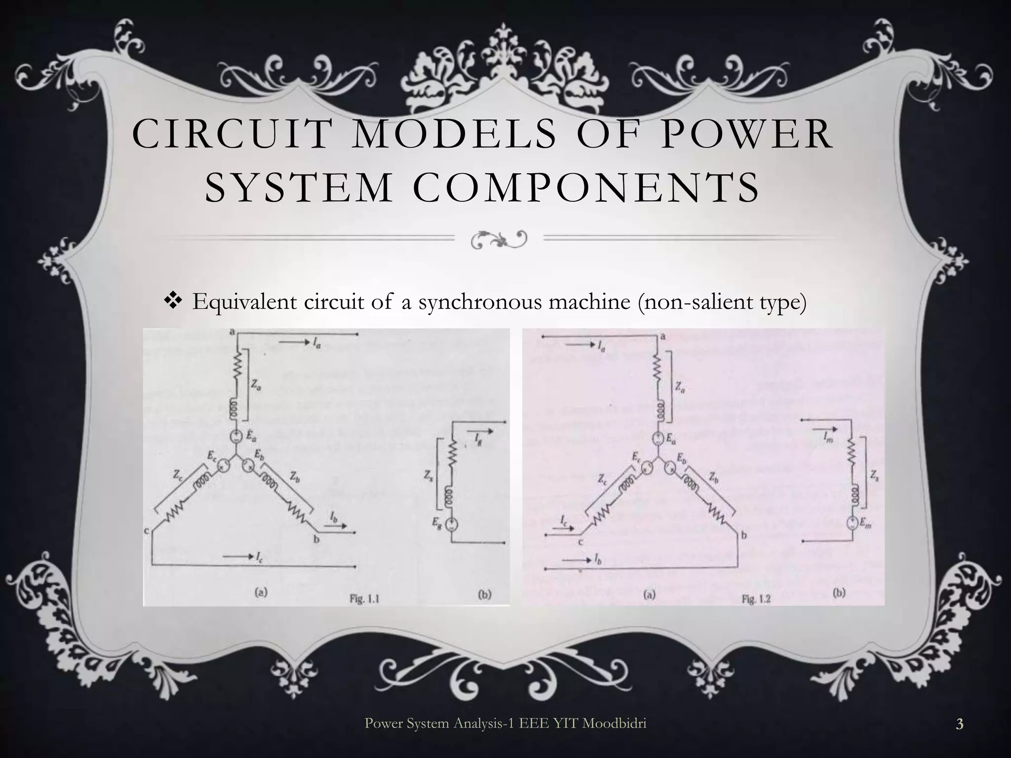
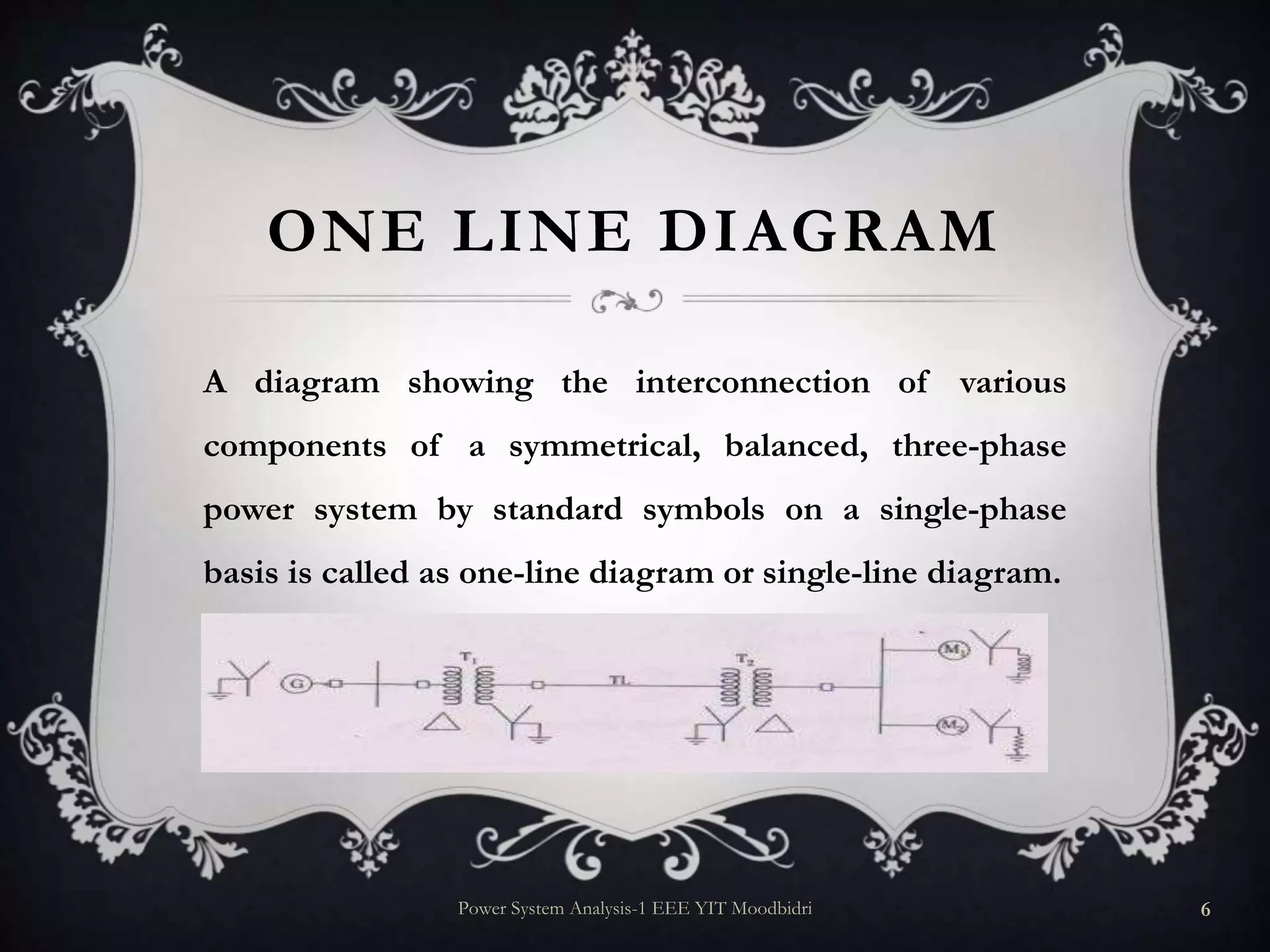
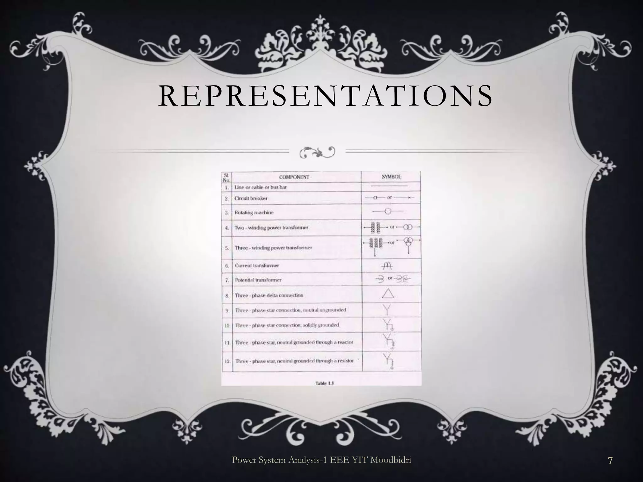
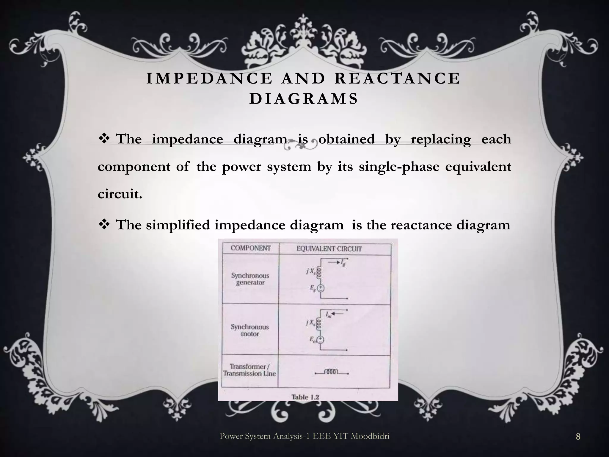
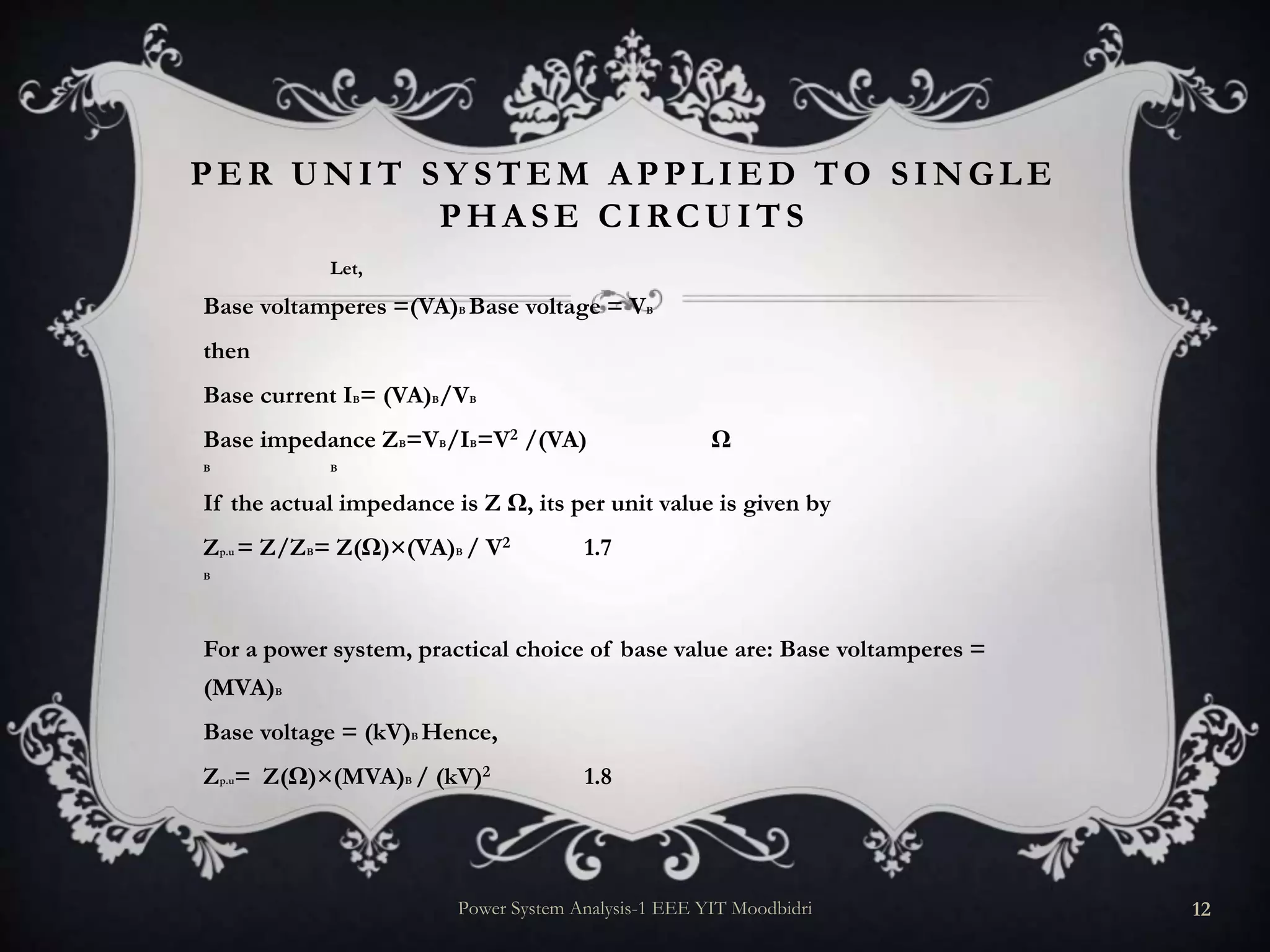
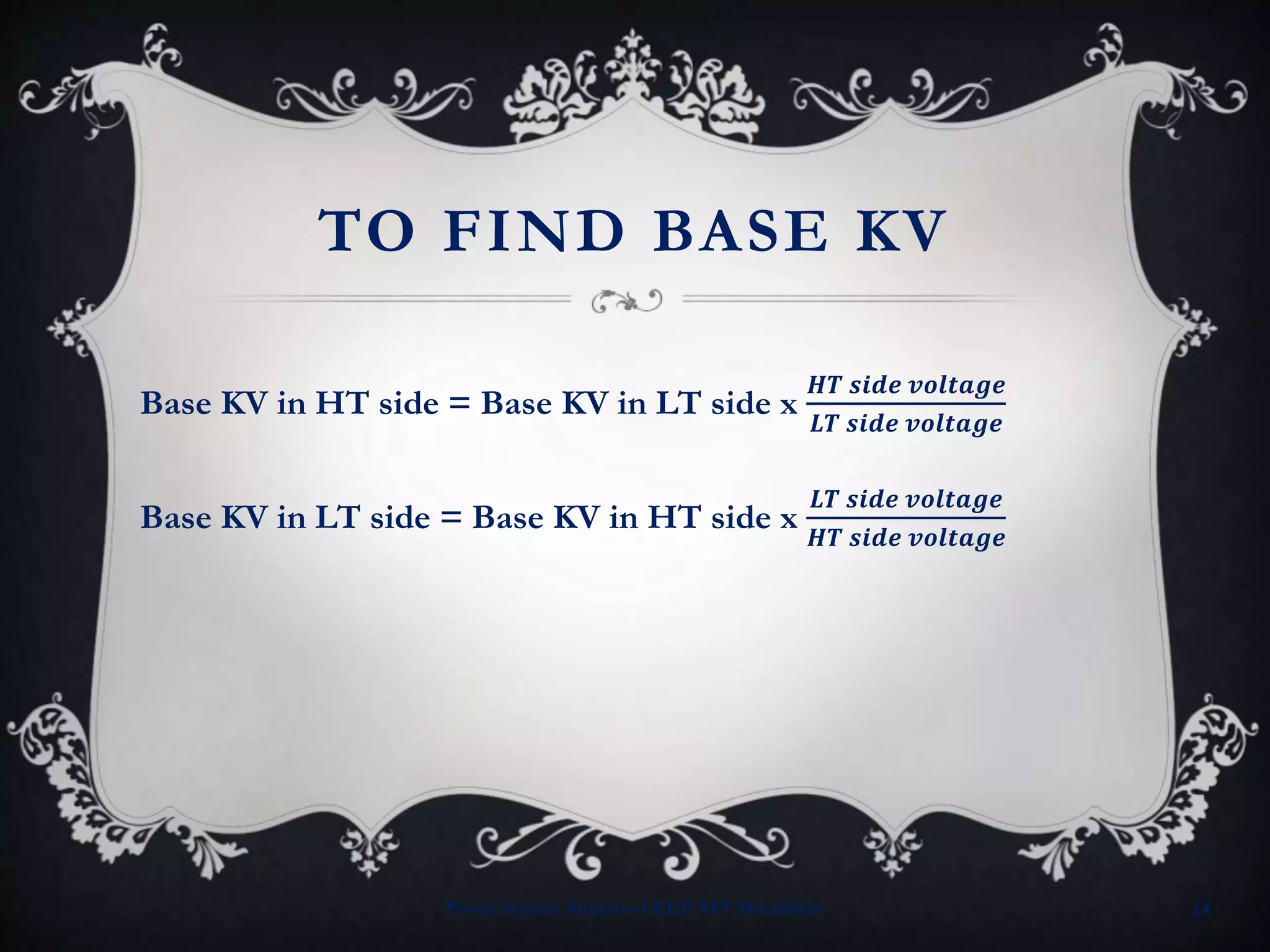
1. REPRESENTATION OF
POWER SYSTEM
COMPONENTS
Mr. Prasanna Kumar
Department of Electrical & Electronics Engineering
Yenepoya Institute of Technology, Moodbidri
Power System Analysis-1 EEE YIT Moodbidri 1
2. INTRODUCTION
A power system mainly consists of generating stations,
transmission lines and distribution systems.
Generating stations and distribution systems are connected
through transmission lines, which also connect one power
system grid to another.
A distribution system connects all loads in a particular area
to the transmission lines.
Power System Analysis-1 EEE YIT Moodbidri 2
3. CIRCUIT MODELS OF POWER
SYSTEM COMPONENTS
Equivalent circuit of a synchronous machine (non-salient type)
Power System Analysis-1 EEE YIT Moodbidri 3
4. EQUIVA LENT CIRCUIT OF A TWO W INDING
TR A NSFOR MER & TR A NSMISSION LINE
Power System Analysis-1 EEE YIT Moodbidri 4
5. EQUIVA LENT CIRCUITS OF STA TIC &
DY NA MIC LOA DS
Static loads - Electric furnaces, induction heaters,
lamps etc are the static loads on a power system network.
They are usually represented by their equivalent
impedances
Dynamic Loads - Synchronous motors and induction
motors
Power System Analysis-1 EEE YIT Moodbidri 5
6. ONE LINE DIAGRAM
A diagram showing the interconnection of various
components of a symmetrical, balanced, three-phase
power system by standard symbols on a single-phase
basis is called as one-line diagram or single-line diagram.
Power System Analysis-1 EEE YIT Moodbidri 6
8. IMPEDA NCE A ND R EA CTA NCE
DIA GR A MS
The impedance diagram is obtained by replacing each
component of the power system by its single-phase equivalent
circuit.
The simplified impedance diagram is the reactance diagram
Power System Analysis-1 EEE YIT Moodbidri 8
10. PER UNIT (P.U) SYSTEM
The per unit value of any quantity is defined as the ratio of the
actual value of the quantity in any unit to the base or reference
value in the same unit
If we choose, 50A as the base current, then a current of 30 A is
equal to 30/50 = 0.6 in per unit
Power System Analysis-1 EEE YIT Moodbidri 10
11. A DVA NTA GES OF PER UNIT
COMPUTA TIONS
Manufacturers usually specify the impedance of an apparatus in per unit or per cent
value on the base of the name plate rating of the apparatus.
The per unit impedance of the same type of machines, may be of different ratings,
lie within a narrow range. However, the ohmic values differ materially for machines of
different ratings. Hence, if the per unit impedance of a generator is not known, say,
then it can be chosen from a set of tabulated values.
The per unit impedance of transformer is the same referred to either side of it.
The method of connection of transformers (Y-Y, Y- Δ etc ) do not effect the per unit
impedance of the transformer.
The greatest advantage of using per unit values is that it makes the calculations
relatively easier.
Power System Analysis-1 EEE YIT Moodbidri 11
12. PER UNIT SY STEM A PPLIED TO SINGLE
PHA SE CIRCUITS
Let,
Base voltamperes =(VA)B Base voltage = VB
then
Base current IB= (VA)B/VB
Base impedance ZB=VB/IB=V2 /(VA) Ω
B B
If the actual impedance is Z Ω, its per unit value is given by
Zp.u = Z/ZB= Z(Ω)×(VA)B / V2 1.7
B
For a power system, practical choice of base value are: Base voltamperes =
(MVA)B
Base voltage = (kV)B Hence,
Zp.u= Z(Ω)×(MVA)B / (kV)2 1.8
Power System Analysis-1 EEE YIT Moodbidri 12
13. CHA NGE OF BA SE QUA NTITIES
Let (kV)B, old and (MVA)B, old represent old base values and (kV)B, new and
(MVA)B, new represent new base values.
Zp.u, old = p.u impedance of a circuit element on old base
=Z(Ω)×(MVA)B, old / (kV)2B, old ……………….(1)
Zp.u, new = p.u impedance of a circuit element on new base
=Z(Ω)×(MVA)B, new / (kV)2B, new …………………(2)
Dividing equation 1 by equation 2 and rearranging, we get
Zp.u.new = Zpu.old×( (MVA)B,new /(MVA)B,old )× ( (kV)B2.old /(kV)B2 new
.
Power System Analysis-1 EEE YIT Moodbidri 13
14. TO FIND BASE KV
Base KV in HT side = Base KV in LT side x
𝑯𝑻 𝒔𝒊𝒅𝒆 𝒗𝒐𝒍𝒕𝒂𝒈𝒆
𝑳𝑻 𝒔𝒊𝒅𝒆 𝒗𝒐𝒍𝒕𝒂𝒈𝒆
Base KV in LT side = Base KV in HT side x
𝑳𝑻 𝒔𝒊𝒅𝒆 𝒗𝒐𝒍𝒕𝒂𝒈𝒆
𝑯𝑻 𝒔𝒊𝒅𝒆 𝒗𝒐𝒍𝒕𝒂𝒈𝒆
Power System Analysis-1 EEE YIT Moodbidri 14