Downloaded 115 times


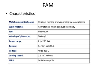
![Plasma Arc Machining (PAM)
or
Plasma Jet machining (PJM)
• Principle
– Material is removed by directing a high velocity jet
of high temperature [11000 to 28000 deg. celcius]
ionized gas on the work piece, which in turn melts
the material from work piece](https://image.slidesharecdn.com/unit5-thermalbasedenergyprocess-180430090930/85/Unit-5-thermal-based-energy-process-19-320.jpg)


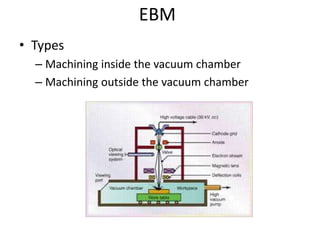
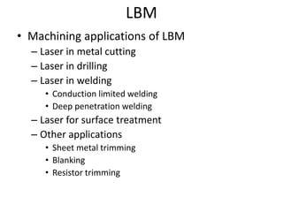
Thermal energy based machining processes like electron beam machining (EBM), laser beam machining (LBM), and plasma arc machining (PAM) work by concentrating heat energy on a small area of the workpiece to melt and vaporize material. EBM uses a beam of high velocity electrons, LBM uses a focused laser beam, and PAM uses a high temperature plasma jet, all to remove tiny bits of workpiece material through localized heating and repetition of the process. While each has advantages like precision and lack of mechanical contact, they also have disadvantages like high equipment costs and low material removal rates.