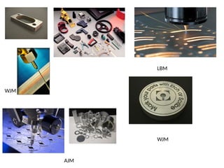
NON-TRADITIONAL MACHINING
Introduction
• Development of harder and difficult to machine materials such as hastalloy,
nitralloy, waspalloy, nimonics carbides, stainless steel and many other high-
strength-temperature –resisitant (HSTR) alloys find wide application in Aerospace,
nuclear engineering .
• Non-traditional manufacturing processes is defined as a group of processes that
remove excess material by various techniques involving mechanical, thermal,
electrical or chemical energy or combinations of these energies but do not use a
sharp cutting tools as it needs to be used for traditional manufacturing processes.
• Extremely hard and brittle materials are difficult to machine by traditional
machining processes such as turning, drilling, shaping and milling.
• Non traditional machining processes, also called advanced manufacturing
processes, are employed where traditional machining processes are not feasible,
satisfactory or economical due to special reasons as outlined below.
 Very hard fragile materials difficult to clamp for traditional machining
 When the work piece is too flexible or slender
 When the shape of the part is too complex
Need of Non traditional machining processes
• To machine newly developed metals and non metals with special properties
‑
that make them difficult or impossible to machine by conventional methods
Difficult to machine material – e.g. same example as above in Inconel, Ti-alloys
or carbides.
• For unusual and/or complex part geometries that cannot easily be
accomplished by conventional machining like Intricate shaped blind hole – e.g.
square hole of 15 mmx15 mm with a depth of 30 mm
• To avoid surface damage that often accompanies conventional machining
• Low Stress Grinding – Electrochemical Grinding is preferred as compared to
conventional grinding
• Machining of composites.
Classification of Non Traditional Machining
1) Mechanical Processes
⎯ Abrasive Jet Machining (AJM)
⎯ Ultrasonic Machining (USM)
⎯ Water Jet Machining (WJM)
⎯ Abrasive Water Jet Machining (AWJM)
2) Electrochemical Processes
⎯ Electrochemical Machining (ECM)
⎯ Electro Chemical Grinding (ECG)
⎯ Electro Jet Drilling (EJD)
3) Electro-Thermal Processes or Thermo Electric Processes
⎯ Electro-Discharge machining (EDM)
⎯ Laser Beam Machining (LBM)
⎯ Electron Beam Machining (EBM)
-Plasma Arc Machining (PAM)
-Ion-Beam Machining(IBM)
4) Chemical Processes
⎯ Chemical Milling (CHM)
⎯ Photochemical Milling (PCM)
Principle of Laser Beam Machining
Laser beam is based on the conversion of electrical energy into light energy
and then to thermal energy.
.
Laser is the term used for the phenomena of amplification of light by stimulated
emission of radiation.
The Setup consists of stimulating light source and a laser rod.
Advantages
1) Any material can be easily machined irrespective of its structure physical and
Mechanical property
2) Unlike conventional machining, there is no direct contact between the tool and the
work piece and no involvement of large scale cutting forces.
3) Tool wear is non existent and can be effectively used for welding of dissimilar
metals as well.
4) Small heat affected zone around the machined surface.
5) Very small holes and cuts can be made with fairly high degree of accuracy.
Disadvantages
6) High capital investment needed
7) Operating cost is also high
8) Highly skilled operators are needed
9) Its application is only limited to thin sections where a very a small amount of metal
removal is involved.
10) Cannot be effectively used to machine highly heat conduction and reflective
materials.
Application
1) Trimming of carbon resistors.
2) Drilling small holes in hard materials like tungsten and ceramics
3) Cutting complex profiles on thin and materials
4) Cutting and engraving patterns on thin films.
5) Trimming sheet metal and plastic parts
Electron Beam Machining
It is a process where high-velocity electrons concentrated into a narrow beam are
directed toward the work piece, creating heat and vaporizing the material.
EBM can be used for very accurate cutting or boring of a wide variety of metals. Surface
finish is better and width is narrower than those for other thermal cutting processes.
Electron Beam Machining
•Filament wire is heated to 250000 C, cloud of electron is emitted by the filament
•Work piece is held in a vacuum chamber and electron beam is focused on to it
magnetically.
•As the electron strike the work piece, this kinetic energy is converted into heat.
•This concentrated heat raises the temperature of work piece materials and vaporizes a
small amount of it, resulting in removal of metal from work piece.
•The reason for using a vacuum chamber is that , if other wise, the beam of electrons
will collide with gas molecules and will scatter.
Applications of Electron Beam Machining
1. Very effective for machining of materials of low heat conductivity and high melting point.
2. Micro machining operation on work piece , used for space nuclear reactors, turbine blades for
supersonic aero-engines.
3. Micro drilling operation (up to 0.002mm ) for thin orifices, dies for wire drawing, parts of electron
microscopes, fiber spinners, injector nozzles for diesel engines etc
Advantages
4. Work piece is not subjected to any physical or metallurgical damage.
5. Heat can be concentrated on a particular spot.
6. An excellent techniques for micromachining
7. There is no contact between the work piece and the tool
Disadvantages
8. High initial investment needed.
9. Highly skilled operator is required to perform the operation
10. Low rate of metal removal and high power consumption.
11. Difficult to produce slots and holes of uniform shapes and dimensions
Plasma Arc Machining
• Here the method of heat generation is different than EDM and LBM.
• In this process gases are heated and charged to plasma state. Plasma
state is the superheated and electrically ionized gases at
approximately 11000 to 30000oC.
• These gases are directed on the work piece in the form of high
velocity stream
Plasma Gun:
• Gases are used to create plasma like, nitrogen, argon, hydrogen or
mixture of these gases.
•The plasma gun consists of a tungsten electrode fitted in the
chamber
• The electrode is given negative polarity and nozzle of the gun is
given positive polarity.
•Supply of gases is maintained into the gun. A strong arc is established
between the two terminals anode and cathode
• There is a collision between molecules of gas and electrons of the
established arc.
•As a result of this collision gas molecules get ionized and heat is
evolved.
•This hot and ionized gas called plasma is directed to the workpiece
with high velocity.
•For 25mm thickness the heat affected zone is 4mm, flow rate of gas
is 2 to 11 m3/hr, current is of the order 50 to 40000 Amps, cutting rate
of 25 to 1700mm/min.
• diameter of holes is 0.8 mm on 6 to 30 mm thick plates
Applications of PAM
1. The chief application of this process is profile cutting of metals, like stainless steel
as controlling movement of spray focus point is easy in case of PAM process.
2. This is also recommended for smaller machining of difficult to machining materials.
Advantages of PAM Process
2. It gives faster production rate.
3. Very hard and brittle metals can be machined.
4. Small cavities can be machined with good dimensional accuracy.
Disadvantages of PAM Process
5. Its initial cost is very high.
6. The process requires over safety precautions which further enhance the initial cost of
the setup.
3. Some of the work piece materials are very much prone to metallurgical changes on
excessive heating so this fact imposes limitations to this process.
4. It is uneconomical for bigger cavities to be machined.
LBM
WJM
WJM
AJM
Electrochemical Machining Processes
• Electrical energy used in combination with Chemical reactions to remove material
• Reverse of electroplating
• Work material must be a conductor
Processes:
• Electrochemical machining (ECM)
• Electrochemical deburring (ECD)
• Electrochemical grinding (ECG)
Adaptation of ECM to remove burrs or round sharp corners on holes in metal parts
produced by conventional through hole drilling .Uses an electrolyte and electrical
‑
current to ionize and remove metal atoms
Electrochemical Deburring (ECD)
Adaptation of ECM to remove burrs or
round sharp corners on holes in metal
parts produced by conventional
through hole drilling
‑
Electrochemical Machining Process
• Electrolysis process that takes place at cathode liberates hydroxyl ions (negatively
charged) and free hydrogen
• The hydroxyl ions combine with the metal ions of the anode to form insoluble metal
hydroxides and the material is removed from the anode
• Electric current is of the order of 50 to 40,000 A at 5 to 30 V , across a gap of 0.05 to
0.7 mm between the tool and the work piece.
• Electrolyte flows through this gap at a velocity of 30 to 60 m/s forced by an inlet
pressure of 20 kgf/cm2
• Material of work piece is removed by anodic dissolution
• Water is used as base of electrolyte in ECM. Normally water soluble NaCl and NaNO3
are used as electrolyte
• Special form of ECM in which a grinding wheel with conductive bond material is used
to augment anodic dissolution of metal part surface
Electrochemical Grinding (ECG)
Applications
1. This is applied in internal finishing of surgical needles and also for their sharpening.
2. Machining of hard, brittle, heat resistant materials without any problem.
3. Drilling of small and deeper holes with very good quality of internal surface finish.
4. Machining of cavities and holes of complicated and irregular shapes.
5. It is used for making inclined and blind holes and finishing of conventionally
machined surfaces.
.
Advantages of ECM Process
1. Machining of hard and brittle material is possible with good quality of surface finish and
dimensional accuracy.
2. Complex shapes can also be easily machined.
3. There is almost negligible tool wear so cost of tool making is only one time investment
for mass production.
4. There is no application of force, no direct contact between tool and work and no
application of heat so there is no scope of mechanical and thermal residual stresses
in the work piece.
5. Very close tolerances can be obtained
Disadvantages of ECM
5. All electricity non-conducting materials can not be machined.
6. Total material and work piece material should be chemically stable with the electrolyte
solution.
7. Designing and making tool is difficult but its life is long so recommended only for mass
production.
8. Accurate feed rate of tool is required to be maintained.
Ultrasonic machining (USM)
Ultrasonic machining (USM) is one of the non-traditional machining process.
Working principle of this process resembles with conventional and metal cutting as in this
process abrasives contained in a slurry are driven at high velocity against the workpiece by
a tool vibrating at low amplitude and high frequency.
Amplitude is kept of the order of 0.07 mm and frequency is maintained at approximately
20,000 Hz.
The workpiece material is removed in the form of extremely small chips.
Normally very hard particle dust is included in the slurry like, Al2O2, silicon carbide, boron
carbide or diamond dust.
Abrasive slurry acts as a multipoint cutting tool and does the similar action as done by a
cutting edge.
Ultrasonic machining (USM)
Principle:
Material is removed by micro-chipping or erosion with abrasive particles
The tool, made of softer material than that of the work piece.
The tool forces the abrasive grits, in the gap between the tool and the workpiece, to
impact normally and successively on the work surface, thereby machining the work
surface.
During one strike, the tool moves down from its most upper remote position with a
starting speed at zero, then it speeds up to finally reach the maximum speed at the
mean position.
The smaller the grit size, the lesser the momentum it receives from the tool.
In the machining process, the tool, at some point, impacts on the largest grits, which
are forced into the tool and work piece.
Applications
• This process is generally applied for the machining of hard and
brittle materials like carbides glass, ceramics, precious stones,
titanium, etc.
• It is used for tool making and punch and die making.
• The workpeice material is normally removed in the form of
very find chips so generated surface quality is extremely good.
• It is widely used for several machining operations like turning,
grinding, trepanning and milling, etc.
Advantages
• Precise machining of brittle materials
• Makes tiny holes (0.3mm);
• Does not produce electric, thermal, chemical damage because
it removes material mechanically.
Disadvantages
Low material removal rate (typically 0.8 cm3/min);
tool wears rapidly,
Abrasive Jet Machining
• A high-velocity jet of dry air, nitrogen, or carbon dioxide containing abrasive particles is
aimed at the work piece surface under controlled conditions.
Applications
– Can cut traditionally hard to cut materials, e.g., composites,
ceramics, glass wood, plastics, rubber, paper, leather,
– Good for materials that cannot stand high temperatures
--Deburring, trimming and deflashing, cleaning, and polishing
– Good for materials that cannot withstand high temperatures of
other methods for stress distortion or metallurgical reasons.
Work materials: thin flat stock of hard, brittle materials (e.g., glass, silicon, mica,
ceramics)
Advantages:
Not required for predrilled holes, no heat, no workpiece deflection (hence suitable for
flexible materials), minimal burr, low capital investment
Limitations
– Material removal rate is slow, nozzle wear rate is high
– Not suitable for mass production because of high maintenance requirements
-
Water Jet Machining
Water Jet Machining
• The water jet machining involves directing a high pressure (150-1000 MPa) high
velocity (540-1400 m/s) water jet(faster than the speed of sound) to the surface
to be machined.
• The kinetic energy of water jet after striking the work surface is reduced to zero
• The bulk of kinetic energy of jet is converted into pressure energy.
• If the local pressure caused by the water jet exceeds the strength of the surface
being machined, the material from the surface gets eroded and a cavity is thus
formed.
• Water is the most common fluid used, but additives such as alcohols, oil products
and glycerol are added when they can be dissolved in water to improve the fluid
characteristics.
• Typical work materials involve soft metals, paper, cloth, wood, leather, rubber,
plastics, and frozen food.
• If the work material is brittle it will fracture, if it is ductile, it will cut well
• The orifice is often made of sapphire and its diameter ranges from 1.2 mm to 0.5 mm:
Water Jet Machine
Advantages
- No heat is produced
- Cut can be started anywhere without the need for predrilled holes
- Burr produced is minimum
- Environmentally safe and friendly manufacturing.
Disadvantages
Water jet technology cuts slower than plasma cutting process, reducing material
processing productivity
Application – Used for cutting composites, plastics, fabrics, rubber, wood products
etc. and used in food processing industry.
Abrasive Water jet machining
• The rate of cutting in water jet machining,
particularly while cutting ductile material,
is quite low.
• Cutting rate can be achieved by mixing
abrasive powder in the water to be used for
machining.
• In this process, a narrow focused, water jet is
mixed with abrasive particles.
• This jet is sprayed with very high pressures
resulting in high velocities that cut through
all materials.
• The presence of abrasive particles in the water jet reduces cutting forces and
enables cutting of thick and hard materials (steel plates over 80-mm thick can be
cut).
• The velocity of the stream is up to 90 m/s, about 2.5 times the speed of sound.
Abrasive Water jet machining

Non Traditional Machining Process 1.pptx

  • 1.
  • 2.
    Introduction • Development ofharder and difficult to machine materials such as hastalloy, nitralloy, waspalloy, nimonics carbides, stainless steel and many other high- strength-temperature –resisitant (HSTR) alloys find wide application in Aerospace, nuclear engineering . • Non-traditional manufacturing processes is defined as a group of processes that remove excess material by various techniques involving mechanical, thermal, electrical or chemical energy or combinations of these energies but do not use a sharp cutting tools as it needs to be used for traditional manufacturing processes. • Extremely hard and brittle materials are difficult to machine by traditional machining processes such as turning, drilling, shaping and milling. • Non traditional machining processes, also called advanced manufacturing processes, are employed where traditional machining processes are not feasible, satisfactory or economical due to special reasons as outlined below.  Very hard fragile materials difficult to clamp for traditional machining  When the work piece is too flexible or slender  When the shape of the part is too complex
  • 3.
    Need of Nontraditional machining processes • To machine newly developed metals and non metals with special properties ‑ that make them difficult or impossible to machine by conventional methods Difficult to machine material – e.g. same example as above in Inconel, Ti-alloys or carbides. • For unusual and/or complex part geometries that cannot easily be accomplished by conventional machining like Intricate shaped blind hole – e.g. square hole of 15 mmx15 mm with a depth of 30 mm • To avoid surface damage that often accompanies conventional machining • Low Stress Grinding – Electrochemical Grinding is preferred as compared to conventional grinding • Machining of composites.
  • 4.
    Classification of NonTraditional Machining 1) Mechanical Processes ⎯ Abrasive Jet Machining (AJM) ⎯ Ultrasonic Machining (USM) ⎯ Water Jet Machining (WJM) ⎯ Abrasive Water Jet Machining (AWJM) 2) Electrochemical Processes ⎯ Electrochemical Machining (ECM) ⎯ Electro Chemical Grinding (ECG) ⎯ Electro Jet Drilling (EJD) 3) Electro-Thermal Processes or Thermo Electric Processes ⎯ Electro-Discharge machining (EDM) ⎯ Laser Beam Machining (LBM) ⎯ Electron Beam Machining (EBM) -Plasma Arc Machining (PAM) -Ion-Beam Machining(IBM) 4) Chemical Processes ⎯ Chemical Milling (CHM) ⎯ Photochemical Milling (PCM)
  • 5.
    Principle of LaserBeam Machining Laser beam is based on the conversion of electrical energy into light energy and then to thermal energy. . Laser is the term used for the phenomena of amplification of light by stimulated emission of radiation. The Setup consists of stimulating light source and a laser rod.
  • 6.
    Advantages 1) Any materialcan be easily machined irrespective of its structure physical and Mechanical property 2) Unlike conventional machining, there is no direct contact between the tool and the work piece and no involvement of large scale cutting forces. 3) Tool wear is non existent and can be effectively used for welding of dissimilar metals as well. 4) Small heat affected zone around the machined surface. 5) Very small holes and cuts can be made with fairly high degree of accuracy. Disadvantages 6) High capital investment needed 7) Operating cost is also high 8) Highly skilled operators are needed 9) Its application is only limited to thin sections where a very a small amount of metal removal is involved. 10) Cannot be effectively used to machine highly heat conduction and reflective materials.
  • 7.
    Application 1) Trimming ofcarbon resistors. 2) Drilling small holes in hard materials like tungsten and ceramics 3) Cutting complex profiles on thin and materials 4) Cutting and engraving patterns on thin films. 5) Trimming sheet metal and plastic parts
  • 8.
    Electron Beam Machining Itis a process where high-velocity electrons concentrated into a narrow beam are directed toward the work piece, creating heat and vaporizing the material. EBM can be used for very accurate cutting or boring of a wide variety of metals. Surface finish is better and width is narrower than those for other thermal cutting processes.
  • 9.
    Electron Beam Machining •Filamentwire is heated to 250000 C, cloud of electron is emitted by the filament •Work piece is held in a vacuum chamber and electron beam is focused on to it magnetically. •As the electron strike the work piece, this kinetic energy is converted into heat. •This concentrated heat raises the temperature of work piece materials and vaporizes a small amount of it, resulting in removal of metal from work piece. •The reason for using a vacuum chamber is that , if other wise, the beam of electrons will collide with gas molecules and will scatter.
  • 10.
    Applications of ElectronBeam Machining 1. Very effective for machining of materials of low heat conductivity and high melting point. 2. Micro machining operation on work piece , used for space nuclear reactors, turbine blades for supersonic aero-engines. 3. Micro drilling operation (up to 0.002mm ) for thin orifices, dies for wire drawing, parts of electron microscopes, fiber spinners, injector nozzles for diesel engines etc Advantages 4. Work piece is not subjected to any physical or metallurgical damage. 5. Heat can be concentrated on a particular spot. 6. An excellent techniques for micromachining 7. There is no contact between the work piece and the tool Disadvantages 8. High initial investment needed. 9. Highly skilled operator is required to perform the operation 10. Low rate of metal removal and high power consumption. 11. Difficult to produce slots and holes of uniform shapes and dimensions
  • 11.
    Plasma Arc Machining •Here the method of heat generation is different than EDM and LBM. • In this process gases are heated and charged to plasma state. Plasma state is the superheated and electrically ionized gases at approximately 11000 to 30000oC. • These gases are directed on the work piece in the form of high velocity stream Plasma Gun: • Gases are used to create plasma like, nitrogen, argon, hydrogen or mixture of these gases. •The plasma gun consists of a tungsten electrode fitted in the chamber • The electrode is given negative polarity and nozzle of the gun is given positive polarity. •Supply of gases is maintained into the gun. A strong arc is established between the two terminals anode and cathode • There is a collision between molecules of gas and electrons of the established arc. •As a result of this collision gas molecules get ionized and heat is evolved. •This hot and ionized gas called plasma is directed to the workpiece with high velocity. •For 25mm thickness the heat affected zone is 4mm, flow rate of gas is 2 to 11 m3/hr, current is of the order 50 to 40000 Amps, cutting rate of 25 to 1700mm/min. • diameter of holes is 0.8 mm on 6 to 30 mm thick plates
  • 12.
    Applications of PAM 1.The chief application of this process is profile cutting of metals, like stainless steel as controlling movement of spray focus point is easy in case of PAM process. 2. This is also recommended for smaller machining of difficult to machining materials. Advantages of PAM Process 2. It gives faster production rate. 3. Very hard and brittle metals can be machined. 4. Small cavities can be machined with good dimensional accuracy. Disadvantages of PAM Process 5. Its initial cost is very high. 6. The process requires over safety precautions which further enhance the initial cost of the setup. 3. Some of the work piece materials are very much prone to metallurgical changes on excessive heating so this fact imposes limitations to this process. 4. It is uneconomical for bigger cavities to be machined.
  • 13.
  • 14.
    Electrochemical Machining Processes •Electrical energy used in combination with Chemical reactions to remove material • Reverse of electroplating • Work material must be a conductor Processes: • Electrochemical machining (ECM) • Electrochemical deburring (ECD) • Electrochemical grinding (ECG) Adaptation of ECM to remove burrs or round sharp corners on holes in metal parts produced by conventional through hole drilling .Uses an electrolyte and electrical ‑ current to ionize and remove metal atoms Electrochemical Deburring (ECD) Adaptation of ECM to remove burrs or round sharp corners on holes in metal parts produced by conventional through hole drilling ‑
  • 15.
    Electrochemical Machining Process •Electrolysis process that takes place at cathode liberates hydroxyl ions (negatively charged) and free hydrogen • The hydroxyl ions combine with the metal ions of the anode to form insoluble metal hydroxides and the material is removed from the anode • Electric current is of the order of 50 to 40,000 A at 5 to 30 V , across a gap of 0.05 to 0.7 mm between the tool and the work piece. • Electrolyte flows through this gap at a velocity of 30 to 60 m/s forced by an inlet pressure of 20 kgf/cm2 • Material of work piece is removed by anodic dissolution • Water is used as base of electrolyte in ECM. Normally water soluble NaCl and NaNO3 are used as electrolyte
  • 16.
    • Special formof ECM in which a grinding wheel with conductive bond material is used to augment anodic dissolution of metal part surface Electrochemical Grinding (ECG) Applications 1. This is applied in internal finishing of surgical needles and also for their sharpening. 2. Machining of hard, brittle, heat resistant materials without any problem. 3. Drilling of small and deeper holes with very good quality of internal surface finish. 4. Machining of cavities and holes of complicated and irregular shapes. 5. It is used for making inclined and blind holes and finishing of conventionally machined surfaces. .
  • 17.
    Advantages of ECMProcess 1. Machining of hard and brittle material is possible with good quality of surface finish and dimensional accuracy. 2. Complex shapes can also be easily machined. 3. There is almost negligible tool wear so cost of tool making is only one time investment for mass production. 4. There is no application of force, no direct contact between tool and work and no application of heat so there is no scope of mechanical and thermal residual stresses in the work piece. 5. Very close tolerances can be obtained Disadvantages of ECM 5. All electricity non-conducting materials can not be machined. 6. Total material and work piece material should be chemically stable with the electrolyte solution. 7. Designing and making tool is difficult but its life is long so recommended only for mass production. 8. Accurate feed rate of tool is required to be maintained.
  • 18.
    Ultrasonic machining (USM) Ultrasonicmachining (USM) is one of the non-traditional machining process. Working principle of this process resembles with conventional and metal cutting as in this process abrasives contained in a slurry are driven at high velocity against the workpiece by a tool vibrating at low amplitude and high frequency. Amplitude is kept of the order of 0.07 mm and frequency is maintained at approximately 20,000 Hz. The workpiece material is removed in the form of extremely small chips. Normally very hard particle dust is included in the slurry like, Al2O2, silicon carbide, boron carbide or diamond dust. Abrasive slurry acts as a multipoint cutting tool and does the similar action as done by a cutting edge.
  • 19.
  • 20.
    Principle: Material is removedby micro-chipping or erosion with abrasive particles The tool, made of softer material than that of the work piece. The tool forces the abrasive grits, in the gap between the tool and the workpiece, to impact normally and successively on the work surface, thereby machining the work surface. During one strike, the tool moves down from its most upper remote position with a starting speed at zero, then it speeds up to finally reach the maximum speed at the mean position. The smaller the grit size, the lesser the momentum it receives from the tool. In the machining process, the tool, at some point, impacts on the largest grits, which are forced into the tool and work piece.
  • 21.
    Applications • This processis generally applied for the machining of hard and brittle materials like carbides glass, ceramics, precious stones, titanium, etc. • It is used for tool making and punch and die making. • The workpeice material is normally removed in the form of very find chips so generated surface quality is extremely good. • It is widely used for several machining operations like turning, grinding, trepanning and milling, etc. Advantages • Precise machining of brittle materials • Makes tiny holes (0.3mm); • Does not produce electric, thermal, chemical damage because it removes material mechanically. Disadvantages Low material removal rate (typically 0.8 cm3/min); tool wears rapidly,
  • 22.
    Abrasive Jet Machining •A high-velocity jet of dry air, nitrogen, or carbon dioxide containing abrasive particles is aimed at the work piece surface under controlled conditions.
  • 23.
    Applications – Can cuttraditionally hard to cut materials, e.g., composites, ceramics, glass wood, plastics, rubber, paper, leather, – Good for materials that cannot stand high temperatures --Deburring, trimming and deflashing, cleaning, and polishing – Good for materials that cannot withstand high temperatures of other methods for stress distortion or metallurgical reasons. Work materials: thin flat stock of hard, brittle materials (e.g., glass, silicon, mica, ceramics) Advantages: Not required for predrilled holes, no heat, no workpiece deflection (hence suitable for flexible materials), minimal burr, low capital investment Limitations – Material removal rate is slow, nozzle wear rate is high – Not suitable for mass production because of high maintenance requirements -
  • 24.
  • 25.
    Water Jet Machining •The water jet machining involves directing a high pressure (150-1000 MPa) high velocity (540-1400 m/s) water jet(faster than the speed of sound) to the surface to be machined. • The kinetic energy of water jet after striking the work surface is reduced to zero • The bulk of kinetic energy of jet is converted into pressure energy. • If the local pressure caused by the water jet exceeds the strength of the surface being machined, the material from the surface gets eroded and a cavity is thus formed. • Water is the most common fluid used, but additives such as alcohols, oil products and glycerol are added when they can be dissolved in water to improve the fluid characteristics. • Typical work materials involve soft metals, paper, cloth, wood, leather, rubber, plastics, and frozen food. • If the work material is brittle it will fracture, if it is ductile, it will cut well • The orifice is often made of sapphire and its diameter ranges from 1.2 mm to 0.5 mm:
  • 26.
  • 27.
    Advantages - No heatis produced - Cut can be started anywhere without the need for predrilled holes - Burr produced is minimum - Environmentally safe and friendly manufacturing. Disadvantages Water jet technology cuts slower than plasma cutting process, reducing material processing productivity Application – Used for cutting composites, plastics, fabrics, rubber, wood products etc. and used in food processing industry.
  • 28.
    Abrasive Water jetmachining • The rate of cutting in water jet machining, particularly while cutting ductile material, is quite low. • Cutting rate can be achieved by mixing abrasive powder in the water to be used for machining. • In this process, a narrow focused, water jet is mixed with abrasive particles. • This jet is sprayed with very high pressures resulting in high velocities that cut through all materials. • The presence of abrasive particles in the water jet reduces cutting forces and enables cutting of thick and hard materials (steel plates over 80-mm thick can be cut). • The velocity of the stream is up to 90 m/s, about 2.5 times the speed of sound.
  • 29.