Download to read offline
![2.2.2.5 Jet cutting nozzle. The nozzle provides a coherent water jet stream for optimum cutting of
low-density, soft material that is considered unmachinable by conventional methods. Nozzles are
normally made from synthetic sapphire. About 200 h of operation are expected from a nozzle, which
becomes damaged by particles of dirt and the accumulation of mineral deposits on the orifice due to
erosive water hardness. A longer nozzle life can be obtained through multistage filtration, which
removes undesired solids of size greater than 0.45 µm. The compact design of the water jet cutting
head promotes integration with motion control systems ranging from two-axis (XY) tables to
sophisticated multiaxis robotic installations.
2.2.2.6 Catcher. The catcher acts as a reservoir for collecting the machining debris entrained in the
water jet. Moreover, it reduces the noise levels [105 decibels (dB)] associated with the reduction in the
velocity of the water jet from Mach 3 to subsonic levels.
2.2.3 Process parameters
Jet nozzle. The standoff distance, shown in Fig. 2.20, is the gap between the jet nozzle (0.1–0.3 mm
diameter) and the workpiece (2.5–6 mm). However for materials used in printed circuit boards, it may
be increased to 13 to 19 mm. For a nozzle of 0.12-mm diameter and cutting rate of 1.1 millimeters per
second (mm/s), McGeough (1988) reported the decrease of the depth of cut at a larger standoff
distance. When cutting fiber-reinforced plastics, reports showed that the increase in machining rate
and use of the small nozzle diameter increased the width of the damaged layer.
Jet fluid. Typical pressures reported by McGeough (1988) are 150 to 1000 MPa, which provide 8 to
80 kW of power. For a given nozzle diameter, the increase in pressure allows more power to be used
in the machining process, which in turn increases the depth of the cut. Jet velocities range between
540 to 1400 m/s. The quality of cutting improves at higher pressures by widening the diameter of the
jet and by lowering the traverse speed. Under such conditions, materials of greater thicknesses and
densities can be cut. Moreover, the larger the pump pressure, the greater will be the depth of the cut.
The fluid used must possess low viscosity to minimize the energy losses and be noncorrosive,
nontoxic, common, and inexpensive. Water is commonly used for cutting alloy steels. Alcohol is used
for cutting meat, while cooking oils are recommended for cutting frozen foods. Figure 2.21
summarizes different parameters affecting the performance of WJM.
Target material. Brittle materials will fracture, while
ductile ones will cut well. Material thicknesses range from
0.8 to 25 mm or more. Table 2.4 shows the cutting rates
for different material thicknesses.
2.2.4 Applications](https://image.slidesharecdn.com/amt-180430090550/85/Amt-2-320.jpg)


![2.1 Ultrasonic Machining
2.1.1 Introduction
Ultrasonic machining (USM) is the removal of hard and brittle materials using an axially oscillating tool
at ultrasonic frequencies [18–20 kilohertz (kHz)]. During that oscillation, the abrasive slurry of B4C or
SiC is continuously fed into the machining zone between a soft tool (brass or steel) and the
workpiece. The abrasive particles are, therefore, hammered into the workpiece surface and cause
chipping of fine particles from it. The oscillating tool, at amplitudes ranging from 10 to 40 μm, imposes
a static pressure on the abrasive grains and feeds down as the material is removed to form the
required tool shape (Fig. 2.1). Balamuth first discovered USM in 1945 during ultrasonic grinding of
abrasive powders. The industrial applications began in the 1950s when the new machine tools
appeared. USM is characterized by the absence of any deleterious effect on the metallic structure of
the workpiece material.
2.1.2 The machining system
The machining system, shown in Figs. 2.2 and 2.3, is composed mainly from the magnetostrictor,
concentrator, tool, and slurry feeding arrangement. The magnetostrictor is energized at the ultrasonic
frequency and produces small-amplitude vibrations. Such a small vibration is amplified using the
constrictor (mechanical amplifier) that holds the tool. The abrasive slurry is pumped between the
oscillating tool and the brittle workpiece. Astatic pressure is applied in the tool-workpiece interface that
maintains the abrasive slurry.
2.1.2.1 The magnetostrictor. The magnetostrictor used in USM, shown in Fig. 2.4, has a high-
frequency winding wound on a magnetostrictor core and a special polarizing winding around an
armature. The magnetostriction effect was first discovered by Joule at Manchester in 1874.
Accordingly, a magnetic field undergoing ultrasonic frequencies causes corresponding changes in a
ferromagnetic object placed within its region of influence. This effect is used to oscillate the USM tool,
which is mounted at the end of a magnetostrictor, at ultrasonic frequencies (18 to 20 kHz). The
method of operation of a magnetostrictor can be explained as follows. The coefficient of
magnetostriction elongation Em is](https://image.slidesharecdn.com/amt-180430090550/85/Amt-8-320.jpg)


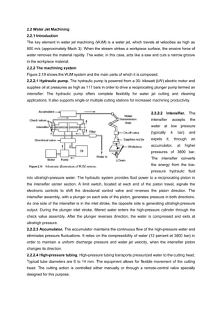
Water jet machining uses a high-pressure water jet to cut materials. The system includes a hydraulic pump, intensifier, accumulator, and cutting head. The intensifier converts low-pressure water to an ultrahigh-pressure water jet of around 3800 bar that is directed through a nozzle. This jet can precisely cut a variety of materials without heat and is used for cutting, drilling, deburring, surface treatment, and more. It has advantages over other methods like no heat affected zone and flexibility but higher hourly costs than mass production methods.


