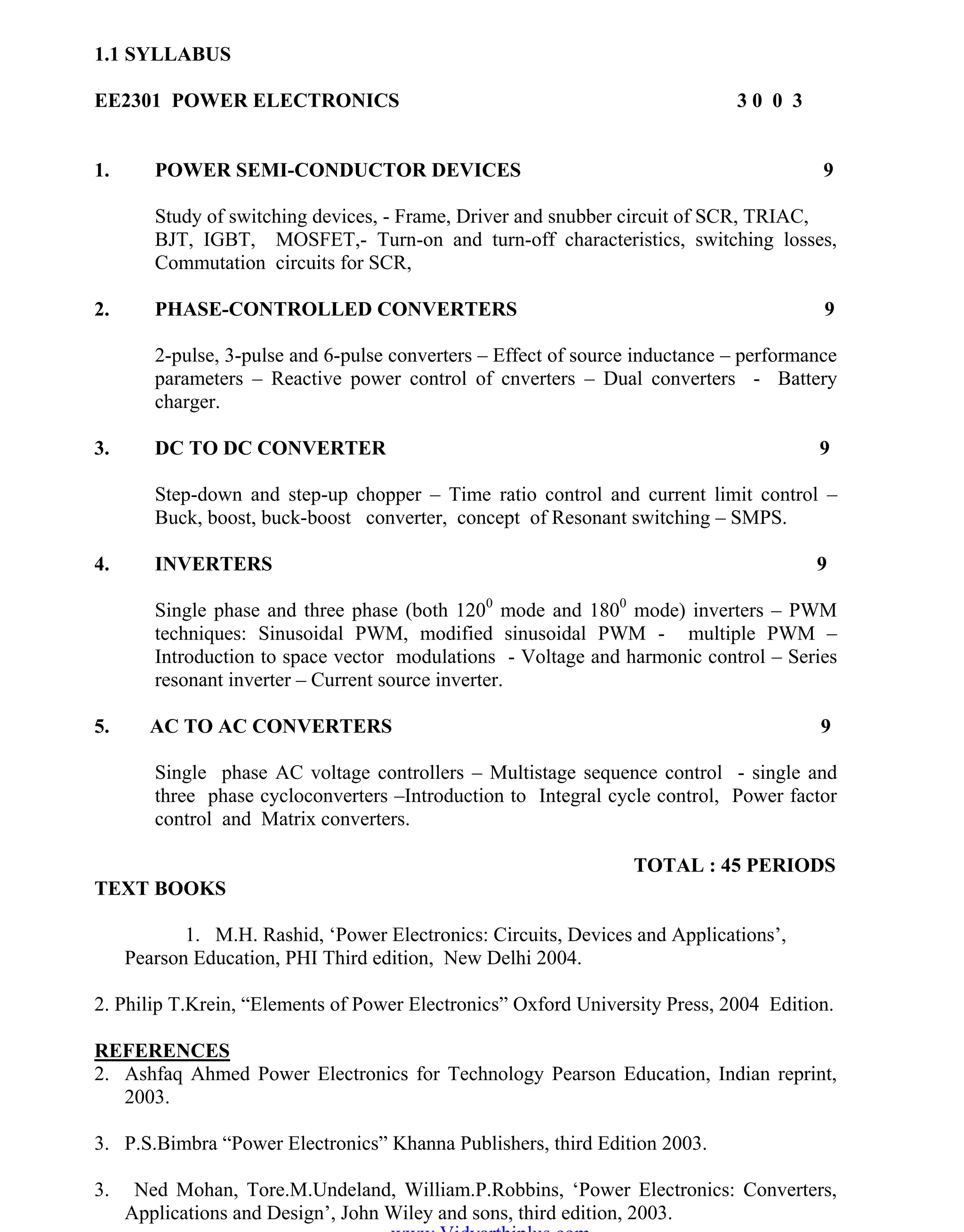
SlideShare a Scribd company logo
OM SATHI
1
EE2301 – POWER ELECTRONICS
1.1 SYLLABUS
EE2301 POWER ELECTRONICS 3 0 0 3
1. POWER SEMI-CONDUCTOR DEVICES 9
Study of switching devices, - Frame, Driver and snubber circuit of SCR, TRIAC,
BJT, IGBT, MOSFET,- Turn-on and turn-off characteristics, switching losses,
Commutation circuits for SCR,
2. PHASE-CONTROLLED CONVERTERS 9
2-pulse, 3-pulse and 6-pulse converters – Effect of source inductance – performance
parameters – Reactive power control of cnverters – Dual converters - Battery
charger.
3. DC TO DC CONVERTER 9
Step-down and step-up chopper – Time ratio control and current limit control –
Buck, boost, buck-boost converter, concept of Resonant switching – SMPS.
4. INVERTERS 9
Single phase and three phase (both 1200
mode and 1800
mode) inverters – PWM
techniques: Sinusoidal PWM, modified sinusoidal PWM - multiple PWM –
Introduction to space vector modulations - Voltage and harmonic control – Series
resonant inverter – Current source inverter.
5. AC TO AC CONVERTERS 9
Single phase AC voltage controllers – Multistage sequence control - single and
three phase cycloconverters –Introduction to Integral cycle control, Power factor
control and Matrix converters.
TOTAL : 45 PERIODS
TEXT BOOKS
1. M.H. Rashid, „Power Electronics: Circuits, Devices and Applications‟,
Pearson Education, PHI Third edition, New Delhi 2004.
2. Philip T.Krein, “Elements of Power Electronics” Oxford University Press, 2004 Edition.
REFERENCES
2. Ashfaq Ahmed Power Electronics for Technology Pearson Education, Indian reprint,
2003.
3. P.S.Bimbra “Power Electronics” Khanna Publishers, third Edition 2003.
3. Ned Mohan, Tore.M.Undeland, William.P.Robbins, „Power Electronics: Converters,
Applications and Design‟, John Wiley and sons, third edition, 2003.
www.Vidyarthiplus.com
OM SAKTHI
DEPARTMENT OF ELECTRICAL AND ELECTRONICS ENGINEERING
3nd
YEAR/ 5th
SEMESTER
1.2 SHORT QUESTIONS AND ANSWERS
UNIT-I
POWER SEMI-CONDUCTOR DEVICES
1. Why IGBT is very popular nowadays?
a. Lower hate requirements
b. Lower switching losses
c. Smaller snubbed circuit requirements
2. What are the different methods to turn on the thyristor?
a. Forward voltage triggering
b. Gate triggering
c. dv/dt triggering
d. Temperature triggering
e. Light triggering
3. What is the difference between power diode and signal diode?
Power diode Signal diode
1.Constructed with n-layer, called
drift region between p+ layer and
n+ layer.Drift region is not present.
2.The voltage, current and power
ratings are higher.Lower3.Power diodes operate at high speeds. Operates at higher
switching speed.
4. IGBT is a voltage controlled device. Why?
Because the controlling parameter is gate-emitter voltage.
5. Power MOSFET is a voltage controlled device. Why?
Because the output (drain) current can be controlled by gate-source voltage.
6. Power BJT is a current controlled device. Why?
Because the output (collector) current can be controlled by base current.
7. What are the different types of power MOSFET?
a. N-channel MOSFET
b. P-channel MOSFET
8. How can a thyristor turned off?
A thyristor can be turned off by making the current flowing through it to zero.
9. Define latching current.
www.Vidyarthiplus.com
OM SATHI
ADHIPARASAKTHI COLLEGE OF ENGINEERING
3
EE2301 – POWER ELECTRONICS
The latching current is defined as the minimum value of anode current which it
must attain during turn on process to maintain conduction when gate signal is removed.
10. Define holding current.
The holding current is defined as the minimum value of anode current below which
it must fall to for turning off the thyristor.
11. What is a snubber circuit?
It consists of a series combination of a resistor and a capacitor in parallel with the
thyristors. It is mainly used for dv / dt protection.
12. What losses occur in a thyristor during working conditions?
a. Forward conduction losses
b. Loss due to leakage current during forward and reverse blocking.
c. Switching losses at turn-on and turn-off.
d. Gate triggering loss.
13. Define hard-driving or over-driving.
When gate current is several times higher than the minimum gate current required, a
thyristor is said to be hard-fired or over-driven. Hard-firing of a thyristor reduces its turn-on
time and enhances its di/dt capability.
14. Define circuit turn off time.
It is defined as the time during which a reverse voltage is applied across the
thyristor during its commutation process.
15. Why circuit turn off time should be greater than the thyristor turn-off time?
Circuit turn off time should be greater than the thyristor turn-off time for reliable
turn-off, otherwise the device may turn-on at an undesired instant, a process called
commutation failure.
17. What is the turn-off time for converter grade SCRs and inverter grade SCRs?
Turn-off time for converter grade SCRs is 50 – 100 ms turn-off time for converter
grade SCRs and inverter grade SCRs and for inverter grade SCRs is 3 – 50 ms.
18. What are the advantages of GTO over SCR?
a. Elimination of commutation of commutating components in forced commutation,
resulting in reduction in cost, weight and volume.
b. Reduction in acoustic noise and electromagnetic noise due to elimination of
commutation chokes.
c. Faster turn-off, permitting high switching frequencies.
d. Improved efficiency of the converters.
www.Vidyarthiplus.com
OM SAKTHI
DEPARTMENT OF ELECTRICAL AND ELECTRONICS ENGINEERING
3nd
YEAR/ 5th
SEMESTER
19. What is meant by phase controlled rectifier?
It converts fixed ac voltage into variable dc voltage.
20. Mention some of the applications of controlled rectifier.
a. Steel rolling mills, printing press, textile mills and paper mills employing dc
motor drives.
b. DC traction
c. Electro chemical and electro-metallurgical process
d. Portable hand tool drives
e. Magnet power supplies
f. HVDC transmission system
PART- B
1. a) Discuss the different modes of operation of thyristor with the help of static
VI characteristics. (8)
1. b) Explain the construction of SCR with neat sketch. (8)
2. Draw the switching characteristics of SCR and explain it. (16)
3. Discuss the different modes of operation of TRIAC with the help of VI
characteristics. (16)
4. Explain the switching characteristics of TRIAC (16)
5. With the help of neat diagram explain the operation of BJT. (16)
UNIT-II
PHASE-CONTROLLED CONVERTERS
1. What is the function of freewheeling diodes in controlled rectifier?
It serves two process.
a. It prevents the output voltage from becoming negative.
b. The load current is transferred from the main thyristors to the freewheeling diode,
thereby allowing all of its thyristors to regain their blocking states.
2. What are the advantages of freewheeling diodes in a controlled in a controlled
rectifier?
a. Input power factor is improved.
b. Load current waveform is improved and thus the load performance is better.
www.Vidyarthiplus.com
OM SATHI
ADHIPARASAKTHI COLLEGE OF ENGINEERING
5
EE2301 – POWER ELECTRONICS
3. What is meant by delay angle?
The delay angle is defined as the angle between the zero crossing of the input
voltage and the instant the thyristors is fired.
4. What are the advantages of single phase bridge converter over single phase mid-
point converter?
a. SCRs are subjected to a peak-inverse voltage of 2Vm in a fully controlled bridge
rectifier. Hence for same voltage and current ratings of SCrs, power handled by
mid-point configuration is about
b. In mid-point converter, each secondary winding should be able to supply the load
power. As such, the transformer rating in mid-point converter is double the load
rating.
5. What is commutation angle or overlap angle?
The commutation period when outgoing and incoming thyristors are conducting
isknown as overlap period. The angular period, when both devices share conduction is
known as the commutation angle or overlap angle.
6. What are the different methods of firing circuits for line commutated converter?
a. UJT firing circuit.
b. The cosine wave crossing pulse timing control.
c. Digital firing schemes.
7. Give an expression for average voltage of single phase semiconverters.
Average output voltage Vdc = (Vm / _) (1 + cos _ ).
8. What is meant by input power factor in controlled rectifier?
The input power factor is defined as the ratio of the total mean input power to
thetotal RMS input volt-amperes.
PF = ( V1 I1 cos _1 ) / ( Vrms Irms) where V1 = phase voltage, I1 =
fundamentalcomponent of the supply current, _1 = input displacement angle, Irms = supply
rms current.
9. What are the advantages of six pulse converter?
a. Commutation is made simple.
b. Distortion on the ac side is reduced due to the reduction in lower order
harmonics.
c. Inductance reduced in series is considerably reduced.
10. What is meant by commutation?
It is the process of changing the direction of current flow in a particular path of the
circuit. This process is used in thyristors for turning it off.
www.Vidyarthiplus.com
OM SAKTHI
DEPARTMENT OF ELECTRICAL AND ELECTRONICS ENGINEERING
3nd
YEAR/ 5th
SEMESTER
11. What are the types of commutation?
a. Natural commutation
b. Forced commutation
12. What is meant by natural commutation?
Here the current flowing through the thyristor goes through a natural zero and
enable the thyristor to turn off.
13. What is meant by forced commutation?
In this commutation, the current flowing through the thyristor is forced to become
zero by external circuitry.
14. What is meant by dc chopper?
A dc chopper is a high speed static switch used to obtain variable dc voltage from
a constant dc voltage.
15. What are the applications of dc chopper?
a. Battery operated vehicles
b. Traction motor control in electric traction
c. Trolly cars
d. Marine hoists
e. Mine haulers
f. Electric braking.
16. What are the applications of dc chopper?
Chopper provides
a. High efficiency
b. Smooth acceleration
c. Fast dynamic response
d. Regeneration
17. What is meant by step-up and step-down chopper?
In a step- down chopper or Buck converter, the average output voltage is less than
the input voltage. In a step- up chopper or Boost converter, the average output voltage is
more than the input voltage.
18. Write down the expression for average output voltage for step down chopper.
Average output voltage for step down chopper V0 = _ Vs, _ is the duty cycle
19. Write down the expression for average output voltage for step up chopper.
Average output voltage for step down chopper V0 = Vs, _ is the duty cycle
1-
www.Vidyarthiplus.com
OM SATHI
ADHIPARASAKTHI COLLEGE OF ENGINEERING
7
EE2301 – POWER ELECTRONICS
20. What is meant by duty-cycle?
Duty cycle is defined as the ratio of the on time of the chopper to the total time
period of the chopper. It is denoted by .
PART-B
1. Discuss the working of 1_ two pulse bridge converter with RLE load using
relevant waveforms. (16)
2. A 1_ two pulse bridge converter feeds power to RLE load with R=6_, L= 6mH,
E = 60v, ac source voltage is 230v, 50Hz for continuous conduction. Find the
average value of load current for firing angle of 50 °. In case one of four SCR‟S
gets open circuited. Find the new value of average load current assuming the
output current as continuous. (16)
3. a) Explain the operation of 1_ semi converter and derive the expressions for its
average and rms output voltage. (8)
3. b) Derive the expressions for harmonic , displacement and power factor of a 1_ full
converter from the fundamental principle. (8)
4. Explain the working of 1_ full converter with RL load and derive the expression
for the average and rms value. (16)
UNIT-III
DC TO DC CONVERTER
1. What are the two types of control strategies?
a. Time Ratio Control (TRC)
b. Current Limit Control method (CLC)
2. What is meant by TRC?
In TRC, the value of Ton / T is varied in order to change the average output
voltage.
3. What are the two types of TRC?
a. Constant frequency control
b. Variable frequency control
4. What is meant by FM control in a dc chopper?
In frequency modulation control, the chopping frequency f (or the chopping
period T) is varied. Here two controls are possible.
a. On-time Ton is kept constant
b. Off period Toff is kept constant.
www.Vidyarthiplus.com
OM SAKTHI
DEPARTMENT OF ELECTRICAL AND ELECTRONICS ENGINEERING
3nd
YEAR/ 5th
SEMESTER
5. What is meant by PWM control in dc chopper?
In this control method, the on time Ton is varied but chopping frequency is kept
constant. The width of the pulse is varied and hence this type of control is known as Pulse
Width Modulation (PWM).
6. Write down the expression for the average output voltage for step down and step up
chopper.
Average output voltage for step down chopper is VO = VS. Average output
voltage for step up chopper is VO = VS x [1/ ( 1- )].
7. What are the different types of chopper with respect to commutation process?
a. Voltage commutated chopper.
b. Current commutated chopper.
c. Load commutated chopper.
8. What is meant by voltage commutation?
In this process, a charged capacitor momentarily reverse biases the conducting
thyristor and turn it off.
9. What is meant by current commutation?
In this process, a current pulse is made to flow in the reverse direction through the
conducting thyristor and when the net thyristor current becomes zero, it is turned off.
10. What is meant by load commutation?
In this process, the load current flowing through the thyristor either becomes zero or
is transferred to another device from the conducting thyristor.
11. What are the advantages of current commutated chopper?
a. The capacitor always remains charged with the correct polarity.
b. Commutation is reliable as load current is less than the peak commutation current
ICP.
c. The auxiliary thyristor TA is naturally commutated as its current passes through
zero value.
12. What are the advantages of load commutated chopper?
a. Commutating inductor is not required.
b. It is capable of commutating any amount of load current.
c. It can work at high frequencies in the order of kHz.
d. Filtering requirements are minimal.
13. What are the disadvantages of load commutated chopper?
a. For high power applications, efficiency becomes very low because of high
switching losses at high operating frequencies.
b. Freewheeling diode is subjected to twice the supply voltage.
www.Vidyarthiplus.com
OM SATHI
ADHIPARASAKTHI COLLEGE OF ENGINEERING
9
EE2301 – POWER ELECTRONICS
c. Peak load voltage is equal to twice the supply voltage.
d. The commutating capacitor has to carry full load current at a frequency of half
chopping frequency.
e. One thyristor pair should be turned-on only when the other pair is commutated.
This can be realized by sensing the capacitor current that is alternating.
14. What is meant by inverter?
A device that converts dc power into ac power at desired output voltage and
frequency is called an inverter.
15. What are the applications of an inverter?
a. Adjustable speed drives
b. Induction heating
c. Stand-by aircraft power supplies
d. UPS
e. HVDC transmission
16. What are the main classification of inverter?
a. Voltage Source Inverter
b. Current Source Inverter
17. Why thyristors are not preferred for inverters?
Thyristors require extra commutation circuits for turn off which results in increased
complexity of the circuit. For these reasons thyristors are not preferred for inverters.
18. How output frequency is varied in case of a thyristor?
The output frequency is varied by varying the turn off time of the thyristors in the
inverter circuit, i.e. the delay angle of the thyristors is varied.
19. Give two advantages of CSI.
a. CSI does not require any feedback diodes.
b. Commutation circuit is simple as it involves only thyristors.
20. What is the main drawback of a single phase half bridge inverter?
It require a 3-wire dc supply.
PART – B
1. Discuss the principle of operation of DC-DC step down chopper with suitable
waveforms. Derive the expression for its average dc voltage. (16)
2. A step down dc chopper has input voltage of 230v with 10 ohm load, voltage
drop across chopper is 2v, when it is on. For a duty cycle of 0.5.
www.Vidyarthiplus.com
OM SAKTHI
DEPARTMENT OF ELECTRICAL AND ELECTRONICS ENGINEERING
3nd
YEAR/ 5th
SEMESTER
Calculate i) average and rms value of output voltage ii) power delivered to the
load. (16)
3. Explain the two quadrant dc chopper operation with RLE load using suitable
waveforms. (16)
4. a) Explain time ratio control and current limit control strategies. (8)
b) Explain the resonant switching based SMPS. . (8)
5. Explain any one type of switched mode regulator and derive the expression
for it. (16)
UNIT-IV
INVERTERS
1. Why diodes should be connected in antiparallel with the thyristors in inverter
circuits?
For RL loads, load current will not be in phase with load voltage and the diodes
connected in anti parallel will allow the current to flow when the main thyristors are turned
off. These diodes are called feedback diodes.
2. What types of inverters require feedback diodes?
VSI with RL load.
3. What is meant a series inverter?
An inverter in which the commutating elements are connected in series with the
load is called a series inverter.
4. What is the condition to be satisfied in the selection of L and C in a series inverter?
R2 < 4L
5. What is meant a parallel inverter?
An inverter in which the commutating elements are connected in parallel with the
load is called a parallel inverter.
6. What are the applications of a series inverter?
The thyristorised series inverter produces an approximately sinusoidal waveform at a high
output frequency, ranging from 200 Hz to 100kHz. It is commonly used for fixed output
applications such as
a. Ultrasonic generator.
b. Induction heating.
c. Sonar Transmitter
d. Fluorescent lighting.
7. How is the inverter circuit classified based on commutation circuitry?
a. Line commutated inverters.
www.Vidyarthiplus.com
OM SATHI
ADHIPARASAKTHI COLLEGE OF ENGINEERING
11
EE2301 – POWER ELECTRONICS
b. Load commutated inverters.
c. Self commutated inverters.
d. Forced commutated inverters.
8. What is meant by McMurray inverter?
It is an impulse commutated inverter which relies on LC circuit and an auxiliary
thyristor for commutation in the load circuit.
9. What are the applications of a CSI?
a. Induction heating
b. Lagging VAR compensation
c. Speed control of ac motors
d. Synchronous motor starting.
10. What is meant by PWM control?
In this method, a fixed dc input voltage is given to the inverter and a controlled
ac output voltage is obtained by adjusting the on and off periods of the inverter
components. This is the most popular method of controlling the output voltage and this
method is termed as PWM control
.
11. What are the advantages of PWM control?
a. The output voltage can be obtained without any additional components.
b. Lower order harmonics can be eliminated or minimized along with its output
voltage control. As the higher order harmonics can be filtered easily, the filtering
requirements are minimized.
12. What are the disadvantages of the harmonics present in the inverter system?
a. Harmonic currents will lead to excessive heating in the induction motors. This
will reduce the load carrying capacity of the motor.
b. If the control and the regulating circuits are not properly shielded, harmonics
from power ride can affect their operation and malfunctioning can result.
c. Harmonic currents cause losses in the ac system and can even some time produce
resonance in the system. Under resonant conditions, the instrumentation and
metering can be affected.
d. On critical loads, torque pulsation produced by the harmonic current can be
useful.
13. What are the methods of reduction of harmonic content?
a. Transformer connections
b. Sinusoidal PWM
c. Multiple commutation in each cycle
d. Stepped wave inverters
14. Compare CSI and VSI.
S. No. VSI CSI
www.Vidyarthiplus.com
OM SAKTHI
DEPARTMENT OF ELECTRICAL AND ELECTRONICS ENGINEERING
3nd
YEAR/ 5th
SEMESTER
1.Input voltage is maintained Constant
Input current is constant but adjustable
2.The output voltage does not depend on the load The output current does not
depend on the load
3.The magnitude of the output current and its waveform depends on the nature of
the load impedance The magnitude of the output voltage
and its waveform depends on the nature of the load impedance
4.It requires feedback diodes It does not requires feedback diodes
5. Commutation circuit is complicated i.e. it contains capacitors and inductors.
Commutation circuit is simple i.e. it contains only capacitors.
15. What are the disadvantages of PWM control?
SCRs are expensive as they must possess low turn-on and turn-off times.
16. What does ac voltage controller mean?
It is device which converts fixed alternating voltage into a variable voltage
without change in frequency.
17. What are the applications of ac voltage controllers?
a. Domestic and industrial heating
b. Lighting control
c. Speed control of single phase and three phase ac motors
d. Transformer tap changing
18. What are the advantages of ac voltage controllers?
a. High efficiency
b. Flexibility in control
c. Less maintenance
19. What are the disadvantages of ac voltage controllers?
The main draw back is the introduction of harmonics in the supply current and the
load voltage waveforms particularly at low output voltages
.
20. What are the two methods of control in ac voltage controllers?
a. ON-OFF control
b. Phase control
PART – B
1. Explain the operation of single phase half bridge inverter with a neat
sketch. (16)
2. The single phase half bridge inverter has resistive load of R=10 ohm and dc
input voltage is 220v. Determine rms output voltage, average value, rms
current and output power. (16)
3. Explain the operation of single phase full bridge inverter with neat
sketch. (16)
www.Vidyarthiplus.com
OM SATHI
ADHIPARASAKTHI COLLEGE OF ENGINEERING
13
EE2301 – POWER ELECTRONICS
4. The single phase full bridge inverter has resistive load of R=2.4 ohm and dc
input voltage is 48v. Determine rms output voltage at the fundamental
frequency, output power. And the total harmonic distortion. (16)
5. Describe the working of three phase inverter with suitable waveform (16)
UNIT-V
AC TO AC CONVERTERS
1. What is the difference between ON-OFF control and phase control?
ON-OFF control: In this method, the thyristors are employed as
switches to connect the load circuit to the source for a few cycles of the load voltage and
disconnect it for another few cycles. Phase control: In this method, thyristor switches
connect the load to the ac source for a portion of each half cycle of input voltage.
2. What is the advantage of ON-OFF control?
Due to zero-voltage and zero current switching of thyristors, the harmonics
generated by the switching action are reduced.
3. What is the disadvantage of ON-OFF control?
This type of control is applicable in systems that have high mechanical inertia and
high thermal time constant.
4. What is the duty cycle in ON-OFF control method?
Duty cycle K = n/ (n + m), where n = no. of ON cycles, m = no. of OFF cycles.
5. What is meant by unidirectional or half-wave ac voltage controller?
Here the power flow is controlled only during the positive half-cycle of the input
voltage.
6. What are the disadvantages of unidirectional or half-wave ac voltage controller?
a. Due to the presence of diode on the circuit, the control range is limited and the
effective RMS output voltage can be varied between 70.7% and 100%.
b. The input current and output voltage are asymmetrical and contain a dc
component. If there is an input transformer, saturation problem will occur
c. It is only used for low power resistive load.
7. What is meant by bidirectional or half-wave ac voltage controller?
Here the power flow is controlled during both cycles of the input voltage.
8. What is the control range of firing angle in ac voltage controller with RL load?
The control range is F < a <180°, where F = load power factor angle.
www.Vidyarthiplus.com
OM SAKTHI
DEPARTMENT OF ELECTRICAL AND ELECTRONICS ENGINEERING
3nd
YEAR/ 5th
SEMESTER
9. What type of gating signal is used in single phase ac voltage controller with RL
load?
High frequency carrier gating signal is used for single phase ac voltage controller
with RL load.
10. What are the disadvantages of continuous gating signal?
a. More heating of the SCR gate.
b. Increases the size of pulse transformer.
11. What is meant by high frequency carrier gating?
Thyristor is turned on by using a train of pulses from a to p. This type of signal
is called as high frequency carrier gating.
12. What is meant by sequence control of ac voltage regulators?
It means that the stages of voltage controllers in parallel triggered in a proper
sequence one after the other so as to obtain a variable output with low harmonic content.
13. What are the advantages of sequence control of ac voltage regulators?
a. System power factor is improved.
b. Harmonics are reduced in the source current and the load voltage.
14. What is meant by cyclo-converter?
It converts input power at one frequency to output power at another frequency
with one-stage conversion. Cycloconverter is also known as frequency changer.
15. What are the two types of cyclo-converters?
a. Step-up cyclo-converters
b. Step-down cyclo-converters
16. What is meant by step-up cyclo-converters?
In these converters, the output frequency is less than the supply frequency.
17. What is meant by step-down cyclo-converters?
In these converters, the output frequency is more than the supply frequency.
18. What are the applications of cyclo-converter?
a. Induction heating
b. Speed control of high power ac drives
c. Static VAR generation
www.Vidyarthiplus.com
OM SATHI
ADHIPARASAKTHI COLLEGE OF ENGINEERING
15
EE2301 – POWER ELECTRONICS
d. Power supply in aircraft or ship boards
19. What is meant by positive converter group in a cyclo converter?
The part of the cycloconverter circuit that permits the flow of current during
Positive half cycle of output current is called positive converter group.
20. What is meant by negative converter group in a cyclo converter?
The part of the cyclo converter circuit that permits the flow of current during
negative half cycle of output current is called negative converter group.
PART-B
1. Draw the circuit diagram of 1_ capacitor commutated current source inverter
and explain its operation with equivalent circuits for different modes and
necessary waveforms.
2. Explain the operation of multistage control of AC voltage controllers with neat
diagram.
3. .Explain the operation of 1_ AC voltage controller with RL load.
4. Explain the operation of sequence control of AC voltage controller..
5. Explain the operation of 1_ sinusoidal AC voltage controller..
6. For a 1_ voltage controller, feeding a resistive load, draw the waveforms of source
voltage, gating signals, output voltage and voltage across the SCR. Describe the working
with reference to waveforms drawn.
www.Vidyarthiplus.com

More Related Content

What's hot

Unified Power Flow Controller(upfc)1
Unified Power Flow Controller(upfc)1Unified Power Flow Controller(upfc)1
Unified Power Flow Controller(upfc)1
JayakalyanReddy
 
dc to dc-converter
dc to dc-converterdc to dc-converter
dc to dc-converter
Student
 
Introduction
IntroductionIntroduction
Introduction
jawaharramaya
 
Hvdc circuit breaker
Hvdc circuit breakerHvdc circuit breaker
Hvdc circuit breaker
Clinton Charalse
 
Load dispatch center
Load dispatch centerLoad dispatch center
Load dispatch center
ddxdharmesh
 
Generation of High D.C. Voltage (HVDC generation)
Generation of High D.C. Voltage (HVDC generation)Generation of High D.C. Voltage (HVDC generation)
Generation of High D.C. Voltage (HVDC generation)
RP6997
 
upfc
upfcupfc
Thyristor switched capacitor PPT
Thyristor switched capacitor PPTThyristor switched capacitor PPT
Thyristor switched capacitor PPT
KLS' S GIT, BELGAUM
 
Load Distribution
Load DistributionLoad Distribution
Load Distribution
Arpit Gupta
 
Infinite bus bar in power system
Infinite bus bar in power systemInfinite bus bar in power system
Infinite bus bar in power system
Eklavya Sharma
 
Streamer theory
Streamer theoryStreamer theory
Streamer theory
Mohammed Almatri
 
Z bus building algorithm
Z bus building algorithmZ bus building algorithm
Z bus building algorithm
Karansinh Parmar
 
Inductance of transmission line
Inductance of transmission lineInductance of transmission line
Inductance of transmission line
Anisur Rahman
 
Tripping and control of impulse generators
Tripping and control of impulse generatorsTripping and control of impulse generators
Tripping and control of impulse generators
Fariza Zahari
 
Neutral grounding
Neutral groundingNeutral grounding
Neutral grounding
Vinod Srivastava
 
Power electronics question bank
Power electronics question bankPower electronics question bank
Power electronics question bank
mcpriya04
 
Power system stability and control using facts devices
Power system stability and control using facts devicesPower system stability and control using facts devices
Power system stability and control using facts devices
Ajit Singh Rajawat
 
Electric traction
Electric tractionElectric traction
Electric traction
Dipak Meher
 
3 reactive power and voltage control
3 reactive power and voltage control3 reactive power and voltage control
3 reactive power and voltage control
8141245710
 
Unit 3 FACTS Technology
Unit 3 FACTS TechnologyUnit 3 FACTS Technology
Unit 3 FACTS Technology
SANTOSH GADEKAR
 

What's hot (20)

Unified Power Flow Controller(upfc)1
Unified Power Flow Controller(upfc)1Unified Power Flow Controller(upfc)1
Unified Power Flow Controller(upfc)1
 
dc to dc-converter
dc to dc-converterdc to dc-converter
dc to dc-converter
 
Introduction
IntroductionIntroduction
Introduction
 
Hvdc circuit breaker
Hvdc circuit breakerHvdc circuit breaker
Hvdc circuit breaker
 
Load dispatch center
Load dispatch centerLoad dispatch center
Load dispatch center
 
Generation of High D.C. Voltage (HVDC generation)
Generation of High D.C. Voltage (HVDC generation)Generation of High D.C. Voltage (HVDC generation)
Generation of High D.C. Voltage (HVDC generation)
 
upfc
upfcupfc
upfc
 
Thyristor switched capacitor PPT
Thyristor switched capacitor PPTThyristor switched capacitor PPT
Thyristor switched capacitor PPT
 
Load Distribution
Load DistributionLoad Distribution
Load Distribution
 
Infinite bus bar in power system
Infinite bus bar in power systemInfinite bus bar in power system
Infinite bus bar in power system
 
Streamer theory
Streamer theoryStreamer theory
Streamer theory
 
Z bus building algorithm
Z bus building algorithmZ bus building algorithm
Z bus building algorithm
 
Inductance of transmission line
Inductance of transmission lineInductance of transmission line
Inductance of transmission line
 
Tripping and control of impulse generators
Tripping and control of impulse generatorsTripping and control of impulse generators
Tripping and control of impulse generators
 
Neutral grounding
Neutral groundingNeutral grounding
Neutral grounding
 
Power electronics question bank
Power electronics question bankPower electronics question bank
Power electronics question bank
 
Power system stability and control using facts devices
Power system stability and control using facts devicesPower system stability and control using facts devices
Power system stability and control using facts devices
 
Electric traction
Electric tractionElectric traction
Electric traction
 
3 reactive power and voltage control
3 reactive power and voltage control3 reactive power and voltage control
3 reactive power and voltage control
 
Unit 3 FACTS Technology
Unit 3 FACTS TechnologyUnit 3 FACTS Technology
Unit 3 FACTS Technology
 

Viewers also liked

DataShare - Pauline Ward to University of Edinburgh School of Chemistry - 3 f...
DataShare - Pauline Ward to University of Edinburgh School of Chemistry - 3 f...DataShare - Pauline Ward to University of Edinburgh School of Chemistry - 3 f...
DataShare - Pauline Ward to University of Edinburgh School of Chemistry - 3 f...
University of Edinburgh
 
Electrical machine design ii
Electrical machine design iiElectrical machine design ii
Electrical machine design ii
Palak Ariwala
 
Current source inverter
Current source inverterCurrent source inverter
Current source inverter
Prashant Kumar
 
Design of Electrical Machines Problems & Solutions
Design of Electrical Machines Problems & SolutionsDesign of Electrical Machines Problems & Solutions
Design of Electrical Machines Problems & Solutions
Velalar College of Engineering and Technology
 
Electrical machine design
Electrical machine designElectrical machine design
Electrical machine design
Ramesh Babu
 
Electrical machine design (III-EEE)
Electrical machine design (III-EEE)Electrical machine design (III-EEE)
Electrical machine design (III-EEE)
betasam
 
Electrical machine Design problems with solutions
Electrical machine Design problems with solutionsElectrical machine Design problems with solutions
Electrical machine Design problems with solutions
Velalar College of Engineering and Technology
 
8085 MICROPROCESSOR
8085 MICROPROCESSOR 8085 MICROPROCESSOR
8085 MICROPROCESSOR
THANDAIAH PRABU
 
Phase Controlled Rectifiers
Phase Controlled RectifiersPhase Controlled Rectifiers
Phase Controlled Rectifiers
maneesh001
 
Electric machine
Electric machineElectric machine
Electric machine
ashok261084
 
Power electronics note
Power electronics notePower electronics note
Power electronics note
ravalgautu
 
3 ph induction motor ppt
3 ph induction motor ppt3 ph induction motor ppt
3 ph induction motor ppt
Ajay Balar
 
Report Writing - Introduction section
Report Writing - Introduction sectionReport Writing - Introduction section
Report Writing - Introduction section
Sherrie Lee
 

Viewers also liked (13)

DataShare - Pauline Ward to University of Edinburgh School of Chemistry - 3 f...
DataShare - Pauline Ward to University of Edinburgh School of Chemistry - 3 f...DataShare - Pauline Ward to University of Edinburgh School of Chemistry - 3 f...
DataShare - Pauline Ward to University of Edinburgh School of Chemistry - 3 f...
 
Electrical machine design ii
Electrical machine design iiElectrical machine design ii
Electrical machine design ii
 
Current source inverter
Current source inverterCurrent source inverter
Current source inverter
 
Design of Electrical Machines Problems & Solutions
Design of Electrical Machines Problems & SolutionsDesign of Electrical Machines Problems & Solutions
Design of Electrical Machines Problems & Solutions
 
Electrical machine design
Electrical machine designElectrical machine design
Electrical machine design
 
Electrical machine design (III-EEE)
Electrical machine design (III-EEE)Electrical machine design (III-EEE)
Electrical machine design (III-EEE)
 
Electrical machine Design problems with solutions
Electrical machine Design problems with solutionsElectrical machine Design problems with solutions
Electrical machine Design problems with solutions
 
8085 MICROPROCESSOR
8085 MICROPROCESSOR 8085 MICROPROCESSOR
8085 MICROPROCESSOR
 
Phase Controlled Rectifiers
Phase Controlled RectifiersPhase Controlled Rectifiers
Phase Controlled Rectifiers
 
Electric machine
Electric machineElectric machine
Electric machine
 
Power electronics note
Power electronics notePower electronics note
Power electronics note
 
3 ph induction motor ppt
3 ph induction motor ppt3 ph induction motor ppt
3 ph induction motor ppt
 
Report Writing - Introduction section
Report Writing - Introduction sectionReport Writing - Introduction section
Report Writing - Introduction section
 

Similar to Power Electronics 2 mark Questions

Ee6503(r 13) qb-2013_regulation
Ee6503(r 13) qb-2013_regulationEe6503(r 13) qb-2013_regulation
Ee6503(r 13) qb-2013_regulation
Marimuthu Balasubramaniam
 
Power electronics
Power electronicsPower electronics
Power electronics
psksiva13
 
Powerelectronics questionbank
Powerelectronics questionbankPowerelectronics questionbank
Powerelectronics questionbank
Sudhakar Reddy
 
power electronics (Study Materials)
power electronics (Study Materials)power electronics (Study Materials)
power electronics (Study Materials)
Samsu Deen
 
Industrial electronics 1 marks- polytechnic
Industrial electronics  1 marks- polytechnicIndustrial electronics  1 marks- polytechnic
Industrial electronics 1 marks- polytechnic
Sukesh R
 
Industrial electronics question bank
Industrial electronics question bankIndustrial electronics question bank
Industrial electronics question bank
Sukesh R
 
Industrial electronics 1 marks- polytechnic
Industrial electronics  1 marks- polytechnicIndustrial electronics  1 marks- polytechnic
Industrial electronics 1 marks- polytechnic
Sukesh R
 
Untitled document.PDF
Untitled document.PDFUntitled document.PDF
Untitled document.PDF
AshishRana497089
 
High Voltage Direct Current Transmission Systems 2Mark Materials
High Voltage Direct Current Transmission Systems 2Mark MaterialsHigh Voltage Direct Current Transmission Systems 2Mark Materials
High Voltage Direct Current Transmission Systems 2Mark Materials
Santhosh Kumar
 
SPEED CONTROL OF SEPARATELY EXCITED DC MOTOR USING POWER ELECTRONIC CONVERTER
 SPEED CONTROL OF SEPARATELY EXCITED DC MOTOR USING POWER ELECTRONIC CONVERTER  SPEED CONTROL OF SEPARATELY EXCITED DC MOTOR USING POWER ELECTRONIC CONVERTER
SPEED CONTROL OF SEPARATELY EXCITED DC MOTOR USING POWER ELECTRONIC CONVERTER
ijiert bestjournal
 
Power Electronics interview questions
Power Electronics interview questionsPower Electronics interview questions
Power Electronics interview questions
Engineering Funda
 
IRJET- Design and Implementation of Isolated Multi-Output Flyback Converter
IRJET- Design and Implementation of Isolated Multi-Output Flyback ConverterIRJET- Design and Implementation of Isolated Multi-Output Flyback Converter
IRJET- Design and Implementation of Isolated Multi-Output Flyback Converter
IRJET Journal
 
Dt31574579
Dt31574579Dt31574579
Dt31574579
IJMER
 
Powerelectronicsnote 121011031400-phpapp02
Powerelectronicsnote 121011031400-phpapp02Powerelectronicsnote 121011031400-phpapp02
Powerelectronicsnote 121011031400-phpapp02
neomindx
 
Powerelectronicsnote 121011031400-phpapp02 (1)
Powerelectronicsnote 121011031400-phpapp02 (1)Powerelectronicsnote 121011031400-phpapp02 (1)
Powerelectronicsnote 121011031400-phpapp02 (1)
neomindx
 
Speed Control Of Separately Excited Dc Motor Using A High Efficiency Flyback ...
Speed Control Of Separately Excited Dc Motor Using A High Efficiency Flyback ...Speed Control Of Separately Excited Dc Motor Using A High Efficiency Flyback ...
Speed Control Of Separately Excited Dc Motor Using A High Efficiency Flyback ...
IJERA Editor
 
Module 1 introduction to Power Electronics
Module 1 introduction to Power ElectronicsModule 1 introduction to Power Electronics
Module 1 introduction to Power Electronics
ZahiraTabassum1
 
Module 1 introduction
Module 1 introductionModule 1 introduction
Module 1 introduction
Amreen Khanam
 
Design & Implementation of Zero Voltage Switching Buck Converter
Design & Implementation of Zero Voltage Switching Buck ConverterDesign & Implementation of Zero Voltage Switching Buck Converter
Design & Implementation of Zero Voltage Switching Buck Converter
IJERA Editor
 
Power Electronics SCR and BJT MCQ Questions
Power Electronics SCR and BJT MCQ QuestionsPower Electronics SCR and BJT MCQ Questions
Power Electronics SCR and BJT MCQ Questions
Burdwan University
 

Similar to Power Electronics 2 mark Questions (20)

Ee6503(r 13) qb-2013_regulation
Ee6503(r 13) qb-2013_regulationEe6503(r 13) qb-2013_regulation
Ee6503(r 13) qb-2013_regulation
 
Power electronics
Power electronicsPower electronics
Power electronics
 
Powerelectronics questionbank
Powerelectronics questionbankPowerelectronics questionbank
Powerelectronics questionbank
 
power electronics (Study Materials)
power electronics (Study Materials)power electronics (Study Materials)
power electronics (Study Materials)
 
Industrial electronics 1 marks- polytechnic
Industrial electronics  1 marks- polytechnicIndustrial electronics  1 marks- polytechnic
Industrial electronics 1 marks- polytechnic
 
Industrial electronics question bank
Industrial electronics question bankIndustrial electronics question bank
Industrial electronics question bank
 
Industrial electronics 1 marks- polytechnic
Industrial electronics  1 marks- polytechnicIndustrial electronics  1 marks- polytechnic
Industrial electronics 1 marks- polytechnic
 
Untitled document.PDF
Untitled document.PDFUntitled document.PDF
Untitled document.PDF
 
High Voltage Direct Current Transmission Systems 2Mark Materials
High Voltage Direct Current Transmission Systems 2Mark MaterialsHigh Voltage Direct Current Transmission Systems 2Mark Materials
High Voltage Direct Current Transmission Systems 2Mark Materials
 
SPEED CONTROL OF SEPARATELY EXCITED DC MOTOR USING POWER ELECTRONIC CONVERTER
 SPEED CONTROL OF SEPARATELY EXCITED DC MOTOR USING POWER ELECTRONIC CONVERTER  SPEED CONTROL OF SEPARATELY EXCITED DC MOTOR USING POWER ELECTRONIC CONVERTER
SPEED CONTROL OF SEPARATELY EXCITED DC MOTOR USING POWER ELECTRONIC CONVERTER
 
Power Electronics interview questions
Power Electronics interview questionsPower Electronics interview questions
Power Electronics interview questions
 
IRJET- Design and Implementation of Isolated Multi-Output Flyback Converter
IRJET- Design and Implementation of Isolated Multi-Output Flyback ConverterIRJET- Design and Implementation of Isolated Multi-Output Flyback Converter
IRJET- Design and Implementation of Isolated Multi-Output Flyback Converter
 
Dt31574579
Dt31574579Dt31574579
Dt31574579
 
Powerelectronicsnote 121011031400-phpapp02
Powerelectronicsnote 121011031400-phpapp02Powerelectronicsnote 121011031400-phpapp02
Powerelectronicsnote 121011031400-phpapp02
 
Powerelectronicsnote 121011031400-phpapp02 (1)
Powerelectronicsnote 121011031400-phpapp02 (1)Powerelectronicsnote 121011031400-phpapp02 (1)
Powerelectronicsnote 121011031400-phpapp02 (1)
 
Speed Control Of Separately Excited Dc Motor Using A High Efficiency Flyback ...
Speed Control Of Separately Excited Dc Motor Using A High Efficiency Flyback ...Speed Control Of Separately Excited Dc Motor Using A High Efficiency Flyback ...
Speed Control Of Separately Excited Dc Motor Using A High Efficiency Flyback ...
 
Module 1 introduction to Power Electronics
Module 1 introduction to Power ElectronicsModule 1 introduction to Power Electronics
Module 1 introduction to Power Electronics
 
Module 1 introduction
Module 1 introductionModule 1 introduction
Module 1 introduction
 
Design & Implementation of Zero Voltage Switching Buck Converter
Design & Implementation of Zero Voltage Switching Buck ConverterDesign & Implementation of Zero Voltage Switching Buck Converter
Design & Implementation of Zero Voltage Switching Buck Converter
 
Power Electronics SCR and BJT MCQ Questions
Power Electronics SCR and BJT MCQ QuestionsPower Electronics SCR and BJT MCQ Questions
Power Electronics SCR and BJT MCQ Questions
 

Recently uploaded

5214-1693458878915-Unit 6 2023 to 2024 academic year assignment (AutoRecovere...
5214-1693458878915-Unit 6 2023 to 2024 academic year assignment (AutoRecovere...5214-1693458878915-Unit 6 2023 to 2024 academic year assignment (AutoRecovere...
5214-1693458878915-Unit 6 2023 to 2024 academic year assignment (AutoRecovere...
ihlasbinance2003
 
[JPP-1] - (JEE 3.0) - Kinematics 1D - 14th May..pdf
[JPP-1] - (JEE 3.0) - Kinematics 1D - 14th May..pdf[JPP-1] - (JEE 3.0) - Kinematics 1D - 14th May..pdf
[JPP-1] - (JEE 3.0) - Kinematics 1D - 14th May..pdf
awadeshbabu
 
spirit beverages ppt without graphics.pptx
spirit beverages ppt without graphics.pptxspirit beverages ppt without graphics.pptx
spirit beverages ppt without graphics.pptx
Madan Karki
 
哪里办理(csu毕业证书)查尔斯特大学毕业证硕士学历原版一模一样
哪里办理(csu毕业证书)查尔斯特大学毕业证硕士学历原版一模一样哪里办理(csu毕业证书)查尔斯特大学毕业证硕士学历原版一模一样
哪里办理(csu毕业证书)查尔斯特大学毕业证硕士学历原版一模一样
insn4465
 
22CYT12-Unit-V-E Waste and its Management.ppt
22CYT12-Unit-V-E Waste and its Management.ppt22CYT12-Unit-V-E Waste and its Management.ppt
22CYT12-Unit-V-E Waste and its Management.ppt
KrishnaveniKrishnara1
 
bank management system in java and mysql report1.pdf
bank management system in java and mysql report1.pdfbank management system in java and mysql report1.pdf
bank management system in java and mysql report1.pdf
Divyam548318
 
CHINA’S GEO-ECONOMIC OUTREACH IN CENTRAL ASIAN COUNTRIES AND FUTURE PROSPECT
CHINA’S GEO-ECONOMIC OUTREACH IN CENTRAL ASIAN COUNTRIES AND FUTURE PROSPECTCHINA’S GEO-ECONOMIC OUTREACH IN CENTRAL ASIAN COUNTRIES AND FUTURE PROSPECT
CHINA’S GEO-ECONOMIC OUTREACH IN CENTRAL ASIAN COUNTRIES AND FUTURE PROSPECT
jpsjournal1
 
Recycled Concrete Aggregate in Construction Part III
Recycled Concrete Aggregate in Construction Part IIIRecycled Concrete Aggregate in Construction Part III
Recycled Concrete Aggregate in Construction Part III
Aditya Rajan Patra
 
BPV-GUI-01-Guide-for-ASME-Review-Teams-(General)-10-10-2023.pdf
BPV-GUI-01-Guide-for-ASME-Review-Teams-(General)-10-10-2023.pdfBPV-GUI-01-Guide-for-ASME-Review-Teams-(General)-10-10-2023.pdf
BPV-GUI-01-Guide-for-ASME-Review-Teams-(General)-10-10-2023.pdf
MIGUELANGEL966976
 
IEEE Aerospace and Electronic Systems Society as a Graduate Student Member
IEEE Aerospace and Electronic Systems Society as a Graduate Student MemberIEEE Aerospace and Electronic Systems Society as a Graduate Student Member
IEEE Aerospace and Electronic Systems Society as a Graduate Student Member
VICTOR MAESTRE RAMIREZ
 
ACEP Magazine edition 4th launched on 05.06.2024
ACEP Magazine edition 4th launched on 05.06.2024ACEP Magazine edition 4th launched on 05.06.2024
ACEP Magazine edition 4th launched on 05.06.2024
Rahul
 
Manufacturing Process of molasses based distillery ppt.pptx
Manufacturing Process of molasses based distillery ppt.pptxManufacturing Process of molasses based distillery ppt.pptx
Manufacturing Process of molasses based distillery ppt.pptx
Madan Karki
 
Advanced control scheme of doubly fed induction generator for wind turbine us...
Advanced control scheme of doubly fed induction generator for wind turbine us...Advanced control scheme of doubly fed induction generator for wind turbine us...
Advanced control scheme of doubly fed induction generator for wind turbine us...
IJECEIAES
 
sieving analysis and results interpretation
sieving analysis and results interpretationsieving analysis and results interpretation
sieving analysis and results interpretation
ssuser36d3051
 
PPT on GRP pipes manufacturing and testing
PPT on GRP pipes manufacturing and testingPPT on GRP pipes manufacturing and testing
PPT on GRP pipes manufacturing and testing
anoopmanoharan2
 
Heat Resistant Concrete Presentation ppt
Heat Resistant Concrete Presentation pptHeat Resistant Concrete Presentation ppt
Heat Resistant Concrete Presentation ppt
mamunhossenbd75
 
Technical Drawings introduction to drawing of prisms
Technical Drawings introduction to drawing of prismsTechnical Drawings introduction to drawing of prisms
Technical Drawings introduction to drawing of prisms
heavyhaig
 
Embedded machine learning-based road conditions and driving behavior monitoring
Embedded machine learning-based road conditions and driving behavior monitoringEmbedded machine learning-based road conditions and driving behavior monitoring
Embedded machine learning-based road conditions and driving behavior monitoring
IJECEIAES
 
New techniques for characterising damage in rock slopes.pdf
New techniques for characterising damage in rock slopes.pdfNew techniques for characterising damage in rock slopes.pdf
New techniques for characterising damage in rock slopes.pdf
wisnuprabawa3
 
Exception Handling notes in java exception
Exception Handling notes in java exceptionException Handling notes in java exception
Exception Handling notes in java exception
Ratnakar Mikkili
 

Recently uploaded (20)

5214-1693458878915-Unit 6 2023 to 2024 academic year assignment (AutoRecovere...
5214-1693458878915-Unit 6 2023 to 2024 academic year assignment (AutoRecovere...5214-1693458878915-Unit 6 2023 to 2024 academic year assignment (AutoRecovere...
5214-1693458878915-Unit 6 2023 to 2024 academic year assignment (AutoRecovere...
 
[JPP-1] - (JEE 3.0) - Kinematics 1D - 14th May..pdf
[JPP-1] - (JEE 3.0) - Kinematics 1D - 14th May..pdf[JPP-1] - (JEE 3.0) - Kinematics 1D - 14th May..pdf
[JPP-1] - (JEE 3.0) - Kinematics 1D - 14th May..pdf
 
spirit beverages ppt without graphics.pptx
spirit beverages ppt without graphics.pptxspirit beverages ppt without graphics.pptx
spirit beverages ppt without graphics.pptx
 
哪里办理(csu毕业证书)查尔斯特大学毕业证硕士学历原版一模一样
哪里办理(csu毕业证书)查尔斯特大学毕业证硕士学历原版一模一样哪里办理(csu毕业证书)查尔斯特大学毕业证硕士学历原版一模一样
哪里办理(csu毕业证书)查尔斯特大学毕业证硕士学历原版一模一样
 
22CYT12-Unit-V-E Waste and its Management.ppt
22CYT12-Unit-V-E Waste and its Management.ppt22CYT12-Unit-V-E Waste and its Management.ppt
22CYT12-Unit-V-E Waste and its Management.ppt
 
bank management system in java and mysql report1.pdf
bank management system in java and mysql report1.pdfbank management system in java and mysql report1.pdf
bank management system in java and mysql report1.pdf
 
CHINA’S GEO-ECONOMIC OUTREACH IN CENTRAL ASIAN COUNTRIES AND FUTURE PROSPECT
CHINA’S GEO-ECONOMIC OUTREACH IN CENTRAL ASIAN COUNTRIES AND FUTURE PROSPECTCHINA’S GEO-ECONOMIC OUTREACH IN CENTRAL ASIAN COUNTRIES AND FUTURE PROSPECT
CHINA’S GEO-ECONOMIC OUTREACH IN CENTRAL ASIAN COUNTRIES AND FUTURE PROSPECT
 
Recycled Concrete Aggregate in Construction Part III
Recycled Concrete Aggregate in Construction Part IIIRecycled Concrete Aggregate in Construction Part III
Recycled Concrete Aggregate in Construction Part III
 
BPV-GUI-01-Guide-for-ASME-Review-Teams-(General)-10-10-2023.pdf
BPV-GUI-01-Guide-for-ASME-Review-Teams-(General)-10-10-2023.pdfBPV-GUI-01-Guide-for-ASME-Review-Teams-(General)-10-10-2023.pdf
BPV-GUI-01-Guide-for-ASME-Review-Teams-(General)-10-10-2023.pdf
 
IEEE Aerospace and Electronic Systems Society as a Graduate Student Member
IEEE Aerospace and Electronic Systems Society as a Graduate Student MemberIEEE Aerospace and Electronic Systems Society as a Graduate Student Member
IEEE Aerospace and Electronic Systems Society as a Graduate Student Member
 
ACEP Magazine edition 4th launched on 05.06.2024
ACEP Magazine edition 4th launched on 05.06.2024ACEP Magazine edition 4th launched on 05.06.2024
ACEP Magazine edition 4th launched on 05.06.2024
 
Manufacturing Process of molasses based distillery ppt.pptx
Manufacturing Process of molasses based distillery ppt.pptxManufacturing Process of molasses based distillery ppt.pptx
Manufacturing Process of molasses based distillery ppt.pptx
 
Advanced control scheme of doubly fed induction generator for wind turbine us...
Advanced control scheme of doubly fed induction generator for wind turbine us...Advanced control scheme of doubly fed induction generator for wind turbine us...
Advanced control scheme of doubly fed induction generator for wind turbine us...
 
sieving analysis and results interpretation
sieving analysis and results interpretationsieving analysis and results interpretation
sieving analysis and results interpretation
 
PPT on GRP pipes manufacturing and testing
PPT on GRP pipes manufacturing and testingPPT on GRP pipes manufacturing and testing
PPT on GRP pipes manufacturing and testing
 
Heat Resistant Concrete Presentation ppt
Heat Resistant Concrete Presentation pptHeat Resistant Concrete Presentation ppt
Heat Resistant Concrete Presentation ppt
 
Technical Drawings introduction to drawing of prisms
Technical Drawings introduction to drawing of prismsTechnical Drawings introduction to drawing of prisms
Technical Drawings introduction to drawing of prisms
 
Embedded machine learning-based road conditions and driving behavior monitoring
Embedded machine learning-based road conditions and driving behavior monitoringEmbedded machine learning-based road conditions and driving behavior monitoring
Embedded machine learning-based road conditions and driving behavior monitoring
 
New techniques for characterising damage in rock slopes.pdf
New techniques for characterising damage in rock slopes.pdfNew techniques for characterising damage in rock slopes.pdf
New techniques for characterising damage in rock slopes.pdf
 
Exception Handling notes in java exception
Exception Handling notes in java exceptionException Handling notes in java exception
Exception Handling notes in java exception
 

Power Electronics 2 mark Questions

  • 1. OM SATHI 1 EE2301 – POWER ELECTRONICS 1.1 SYLLABUS EE2301 POWER ELECTRONICS 3 0 0 3 1. POWER SEMI-CONDUCTOR DEVICES 9 Study of switching devices, - Frame, Driver and snubber circuit of SCR, TRIAC, BJT, IGBT, MOSFET,- Turn-on and turn-off characteristics, switching losses, Commutation circuits for SCR, 2. PHASE-CONTROLLED CONVERTERS 9 2-pulse, 3-pulse and 6-pulse converters – Effect of source inductance – performance parameters – Reactive power control of cnverters – Dual converters - Battery charger. 3. DC TO DC CONVERTER 9 Step-down and step-up chopper – Time ratio control and current limit control – Buck, boost, buck-boost converter, concept of Resonant switching – SMPS. 4. INVERTERS 9 Single phase and three phase (both 1200 mode and 1800 mode) inverters – PWM techniques: Sinusoidal PWM, modified sinusoidal PWM - multiple PWM – Introduction to space vector modulations - Voltage and harmonic control – Series resonant inverter – Current source inverter. 5. AC TO AC CONVERTERS 9 Single phase AC voltage controllers – Multistage sequence control - single and three phase cycloconverters –Introduction to Integral cycle control, Power factor control and Matrix converters. TOTAL : 45 PERIODS TEXT BOOKS 1. M.H. Rashid, „Power Electronics: Circuits, Devices and Applications‟, Pearson Education, PHI Third edition, New Delhi 2004. 2. Philip T.Krein, “Elements of Power Electronics” Oxford University Press, 2004 Edition. REFERENCES 2. Ashfaq Ahmed Power Electronics for Technology Pearson Education, Indian reprint, 2003. 3. P.S.Bimbra “Power Electronics” Khanna Publishers, third Edition 2003. 3. Ned Mohan, Tore.M.Undeland, William.P.Robbins, „Power Electronics: Converters, Applications and Design‟, John Wiley and sons, third edition, 2003. www.Vidyarthiplus.com www.Vidyarthiplus.com www.Vidyarthiplus.com
  • 2. OM SAKTHI DEPARTMENT OF ELECTRICAL AND ELECTRONICS ENGINEERING 3nd YEAR/ 5th SEMESTER 1.2 SHORT QUESTIONS AND ANSWERS UNIT-I POWER SEMI-CONDUCTOR DEVICES 1. Why IGBT is very popular nowadays? a. Lower hate requirements b. Lower switching losses c. Smaller snubbed circuit requirements 2. What are the different methods to turn on the thyristor? a. Forward voltage triggering b. Gate triggering c. dv/dt triggering d. Temperature triggering e. Light triggering 3. What is the difference between power diode and signal diode? Power diode Signal diode 1.Constructed with n-layer, called drift region between p+ layer and n+ layer.Drift region is not present. 2.The voltage, current and power ratings are higher.Lower3.Power diodes operate at high speeds. Operates at higher switching speed. 4. IGBT is a voltage controlled device. Why? Because the controlling parameter is gate-emitter voltage. 5. Power MOSFET is a voltage controlled device. Why? Because the output (drain) current can be controlled by gate-source voltage. 6. Power BJT is a current controlled device. Why? Because the output (collector) current can be controlled by base current. 7. What are the different types of power MOSFET? a. N-channel MOSFET b. P-channel MOSFET 8. How can a thyristor turned off? A thyristor can be turned off by making the current flowing through it to zero. 9. Define latching current. www.Vidyarthiplus.com www.Vidyarthiplus.com
  • 3. OM SATHI ADHIPARASAKTHI COLLEGE OF ENGINEERING 3 EE2301 – POWER ELECTRONICS The latching current is defined as the minimum value of anode current which it must attain during turn on process to maintain conduction when gate signal is removed. 10. Define holding current. The holding current is defined as the minimum value of anode current below which it must fall to for turning off the thyristor. 11. What is a snubber circuit? It consists of a series combination of a resistor and a capacitor in parallel with the thyristors. It is mainly used for dv / dt protection. 12. What losses occur in a thyristor during working conditions? a. Forward conduction losses b. Loss due to leakage current during forward and reverse blocking. c. Switching losses at turn-on and turn-off. d. Gate triggering loss. 13. Define hard-driving or over-driving. When gate current is several times higher than the minimum gate current required, a thyristor is said to be hard-fired or over-driven. Hard-firing of a thyristor reduces its turn-on time and enhances its di/dt capability. 14. Define circuit turn off time. It is defined as the time during which a reverse voltage is applied across the thyristor during its commutation process. 15. Why circuit turn off time should be greater than the thyristor turn-off time? Circuit turn off time should be greater than the thyristor turn-off time for reliable turn-off, otherwise the device may turn-on at an undesired instant, a process called commutation failure. 17. What is the turn-off time for converter grade SCRs and inverter grade SCRs? Turn-off time for converter grade SCRs is 50 – 100 ms turn-off time for converter grade SCRs and inverter grade SCRs and for inverter grade SCRs is 3 – 50 ms. 18. What are the advantages of GTO over SCR? a. Elimination of commutation of commutating components in forced commutation, resulting in reduction in cost, weight and volume. b. Reduction in acoustic noise and electromagnetic noise due to elimination of commutation chokes. c. Faster turn-off, permitting high switching frequencies. d. Improved efficiency of the converters. www.Vidyarthiplus.com www.Vidyarthiplus.com
  • 4. OM SAKTHI DEPARTMENT OF ELECTRICAL AND ELECTRONICS ENGINEERING 3nd YEAR/ 5th SEMESTER 19. What is meant by phase controlled rectifier? It converts fixed ac voltage into variable dc voltage. 20. Mention some of the applications of controlled rectifier. a. Steel rolling mills, printing press, textile mills and paper mills employing dc motor drives. b. DC traction c. Electro chemical and electro-metallurgical process d. Portable hand tool drives e. Magnet power supplies f. HVDC transmission system PART- B 1. a) Discuss the different modes of operation of thyristor with the help of static VI characteristics. (8) 1. b) Explain the construction of SCR with neat sketch. (8) 2. Draw the switching characteristics of SCR and explain it. (16) 3. Discuss the different modes of operation of TRIAC with the help of VI characteristics. (16) 4. Explain the switching characteristics of TRIAC (16) 5. With the help of neat diagram explain the operation of BJT. (16) UNIT-II PHASE-CONTROLLED CONVERTERS 1. What is the function of freewheeling diodes in controlled rectifier? It serves two process. a. It prevents the output voltage from becoming negative. b. The load current is transferred from the main thyristors to the freewheeling diode, thereby allowing all of its thyristors to regain their blocking states. 2. What are the advantages of freewheeling diodes in a controlled in a controlled rectifier? a. Input power factor is improved. b. Load current waveform is improved and thus the load performance is better. www.Vidyarthiplus.com www.Vidyarthiplus.com
  • 5. OM SATHI ADHIPARASAKTHI COLLEGE OF ENGINEERING 5 EE2301 – POWER ELECTRONICS 3. What is meant by delay angle? The delay angle is defined as the angle between the zero crossing of the input voltage and the instant the thyristors is fired. 4. What are the advantages of single phase bridge converter over single phase mid- point converter? a. SCRs are subjected to a peak-inverse voltage of 2Vm in a fully controlled bridge rectifier. Hence for same voltage and current ratings of SCrs, power handled by mid-point configuration is about b. In mid-point converter, each secondary winding should be able to supply the load power. As such, the transformer rating in mid-point converter is double the load rating. 5. What is commutation angle or overlap angle? The commutation period when outgoing and incoming thyristors are conducting isknown as overlap period. The angular period, when both devices share conduction is known as the commutation angle or overlap angle. 6. What are the different methods of firing circuits for line commutated converter? a. UJT firing circuit. b. The cosine wave crossing pulse timing control. c. Digital firing schemes. 7. Give an expression for average voltage of single phase semiconverters. Average output voltage Vdc = (Vm / _) (1 + cos _ ). 8. What is meant by input power factor in controlled rectifier? The input power factor is defined as the ratio of the total mean input power to thetotal RMS input volt-amperes. PF = ( V1 I1 cos _1 ) / ( Vrms Irms) where V1 = phase voltage, I1 = fundamentalcomponent of the supply current, _1 = input displacement angle, Irms = supply rms current. 9. What are the advantages of six pulse converter? a. Commutation is made simple. b. Distortion on the ac side is reduced due to the reduction in lower order harmonics. c. Inductance reduced in series is considerably reduced. 10. What is meant by commutation? It is the process of changing the direction of current flow in a particular path of the circuit. This process is used in thyristors for turning it off. www.Vidyarthiplus.com www.Vidyarthiplus.com
  • 6. OM SAKTHI DEPARTMENT OF ELECTRICAL AND ELECTRONICS ENGINEERING 3nd YEAR/ 5th SEMESTER 11. What are the types of commutation? a. Natural commutation b. Forced commutation 12. What is meant by natural commutation? Here the current flowing through the thyristor goes through a natural zero and enable the thyristor to turn off. 13. What is meant by forced commutation? In this commutation, the current flowing through the thyristor is forced to become zero by external circuitry. 14. What is meant by dc chopper? A dc chopper is a high speed static switch used to obtain variable dc voltage from a constant dc voltage. 15. What are the applications of dc chopper? a. Battery operated vehicles b. Traction motor control in electric traction c. Trolly cars d. Marine hoists e. Mine haulers f. Electric braking. 16. What are the applications of dc chopper? Chopper provides a. High efficiency b. Smooth acceleration c. Fast dynamic response d. Regeneration 17. What is meant by step-up and step-down chopper? In a step- down chopper or Buck converter, the average output voltage is less than the input voltage. In a step- up chopper or Boost converter, the average output voltage is more than the input voltage. 18. Write down the expression for average output voltage for step down chopper. Average output voltage for step down chopper V0 = _ Vs, _ is the duty cycle 19. Write down the expression for average output voltage for step up chopper. Average output voltage for step down chopper V0 = Vs, _ is the duty cycle 1- www.Vidyarthiplus.com www.Vidyarthiplus.com
  • 7. OM SATHI ADHIPARASAKTHI COLLEGE OF ENGINEERING 7 EE2301 – POWER ELECTRONICS 20. What is meant by duty-cycle? Duty cycle is defined as the ratio of the on time of the chopper to the total time period of the chopper. It is denoted by . PART-B 1. Discuss the working of 1_ two pulse bridge converter with RLE load using relevant waveforms. (16) 2. A 1_ two pulse bridge converter feeds power to RLE load with R=6_, L= 6mH, E = 60v, ac source voltage is 230v, 50Hz for continuous conduction. Find the average value of load current for firing angle of 50 °. In case one of four SCR‟S gets open circuited. Find the new value of average load current assuming the output current as continuous. (16) 3. a) Explain the operation of 1_ semi converter and derive the expressions for its average and rms output voltage. (8) 3. b) Derive the expressions for harmonic , displacement and power factor of a 1_ full converter from the fundamental principle. (8) 4. Explain the working of 1_ full converter with RL load and derive the expression for the average and rms value. (16) UNIT-III DC TO DC CONVERTER 1. What are the two types of control strategies? a. Time Ratio Control (TRC) b. Current Limit Control method (CLC) 2. What is meant by TRC? In TRC, the value of Ton / T is varied in order to change the average output voltage. 3. What are the two types of TRC? a. Constant frequency control b. Variable frequency control 4. What is meant by FM control in a dc chopper? In frequency modulation control, the chopping frequency f (or the chopping period T) is varied. Here two controls are possible. a. On-time Ton is kept constant b. Off period Toff is kept constant. www.Vidyarthiplus.com www.Vidyarthiplus.com
  • 8. OM SAKTHI DEPARTMENT OF ELECTRICAL AND ELECTRONICS ENGINEERING 3nd YEAR/ 5th SEMESTER 5. What is meant by PWM control in dc chopper? In this control method, the on time Ton is varied but chopping frequency is kept constant. The width of the pulse is varied and hence this type of control is known as Pulse Width Modulation (PWM). 6. Write down the expression for the average output voltage for step down and step up chopper. Average output voltage for step down chopper is VO = VS. Average output voltage for step up chopper is VO = VS x [1/ ( 1- )]. 7. What are the different types of chopper with respect to commutation process? a. Voltage commutated chopper. b. Current commutated chopper. c. Load commutated chopper. 8. What is meant by voltage commutation? In this process, a charged capacitor momentarily reverse biases the conducting thyristor and turn it off. 9. What is meant by current commutation? In this process, a current pulse is made to flow in the reverse direction through the conducting thyristor and when the net thyristor current becomes zero, it is turned off. 10. What is meant by load commutation? In this process, the load current flowing through the thyristor either becomes zero or is transferred to another device from the conducting thyristor. 11. What are the advantages of current commutated chopper? a. The capacitor always remains charged with the correct polarity. b. Commutation is reliable as load current is less than the peak commutation current ICP. c. The auxiliary thyristor TA is naturally commutated as its current passes through zero value. 12. What are the advantages of load commutated chopper? a. Commutating inductor is not required. b. It is capable of commutating any amount of load current. c. It can work at high frequencies in the order of kHz. d. Filtering requirements are minimal. 13. What are the disadvantages of load commutated chopper? a. For high power applications, efficiency becomes very low because of high switching losses at high operating frequencies. b. Freewheeling diode is subjected to twice the supply voltage. www.Vidyarthiplus.com www.Vidyarthiplus.com
  • 9. OM SATHI ADHIPARASAKTHI COLLEGE OF ENGINEERING 9 EE2301 – POWER ELECTRONICS c. Peak load voltage is equal to twice the supply voltage. d. The commutating capacitor has to carry full load current at a frequency of half chopping frequency. e. One thyristor pair should be turned-on only when the other pair is commutated. This can be realized by sensing the capacitor current that is alternating. 14. What is meant by inverter? A device that converts dc power into ac power at desired output voltage and frequency is called an inverter. 15. What are the applications of an inverter? a. Adjustable speed drives b. Induction heating c. Stand-by aircraft power supplies d. UPS e. HVDC transmission 16. What are the main classification of inverter? a. Voltage Source Inverter b. Current Source Inverter 17. Why thyristors are not preferred for inverters? Thyristors require extra commutation circuits for turn off which results in increased complexity of the circuit. For these reasons thyristors are not preferred for inverters. 18. How output frequency is varied in case of a thyristor? The output frequency is varied by varying the turn off time of the thyristors in the inverter circuit, i.e. the delay angle of the thyristors is varied. 19. Give two advantages of CSI. a. CSI does not require any feedback diodes. b. Commutation circuit is simple as it involves only thyristors. 20. What is the main drawback of a single phase half bridge inverter? It require a 3-wire dc supply. PART – B 1. Discuss the principle of operation of DC-DC step down chopper with suitable waveforms. Derive the expression for its average dc voltage. (16) 2. A step down dc chopper has input voltage of 230v with 10 ohm load, voltage drop across chopper is 2v, when it is on. For a duty cycle of 0.5. www.Vidyarthiplus.com www.Vidyarthiplus.com
  • 10. OM SAKTHI DEPARTMENT OF ELECTRICAL AND ELECTRONICS ENGINEERING 3nd YEAR/ 5th SEMESTER Calculate i) average and rms value of output voltage ii) power delivered to the load. (16) 3. Explain the two quadrant dc chopper operation with RLE load using suitable waveforms. (16) 4. a) Explain time ratio control and current limit control strategies. (8) b) Explain the resonant switching based SMPS. . (8) 5. Explain any one type of switched mode regulator and derive the expression for it. (16) UNIT-IV INVERTERS 1. Why diodes should be connected in antiparallel with the thyristors in inverter circuits? For RL loads, load current will not be in phase with load voltage and the diodes connected in anti parallel will allow the current to flow when the main thyristors are turned off. These diodes are called feedback diodes. 2. What types of inverters require feedback diodes? VSI with RL load. 3. What is meant a series inverter? An inverter in which the commutating elements are connected in series with the load is called a series inverter. 4. What is the condition to be satisfied in the selection of L and C in a series inverter? R2 < 4L 5. What is meant a parallel inverter? An inverter in which the commutating elements are connected in parallel with the load is called a parallel inverter. 6. What are the applications of a series inverter? The thyristorised series inverter produces an approximately sinusoidal waveform at a high output frequency, ranging from 200 Hz to 100kHz. It is commonly used for fixed output applications such as a. Ultrasonic generator. b. Induction heating. c. Sonar Transmitter d. Fluorescent lighting. 7. How is the inverter circuit classified based on commutation circuitry? a. Line commutated inverters. www.Vidyarthiplus.com www.Vidyarthiplus.com
  • 11. OM SATHI ADHIPARASAKTHI COLLEGE OF ENGINEERING 11 EE2301 – POWER ELECTRONICS b. Load commutated inverters. c. Self commutated inverters. d. Forced commutated inverters. 8. What is meant by McMurray inverter? It is an impulse commutated inverter which relies on LC circuit and an auxiliary thyristor for commutation in the load circuit. 9. What are the applications of a CSI? a. Induction heating b. Lagging VAR compensation c. Speed control of ac motors d. Synchronous motor starting. 10. What is meant by PWM control? In this method, a fixed dc input voltage is given to the inverter and a controlled ac output voltage is obtained by adjusting the on and off periods of the inverter components. This is the most popular method of controlling the output voltage and this method is termed as PWM control . 11. What are the advantages of PWM control? a. The output voltage can be obtained without any additional components. b. Lower order harmonics can be eliminated or minimized along with its output voltage control. As the higher order harmonics can be filtered easily, the filtering requirements are minimized. 12. What are the disadvantages of the harmonics present in the inverter system? a. Harmonic currents will lead to excessive heating in the induction motors. This will reduce the load carrying capacity of the motor. b. If the control and the regulating circuits are not properly shielded, harmonics from power ride can affect their operation and malfunctioning can result. c. Harmonic currents cause losses in the ac system and can even some time produce resonance in the system. Under resonant conditions, the instrumentation and metering can be affected. d. On critical loads, torque pulsation produced by the harmonic current can be useful. 13. What are the methods of reduction of harmonic content? a. Transformer connections b. Sinusoidal PWM c. Multiple commutation in each cycle d. Stepped wave inverters 14. Compare CSI and VSI. S. No. VSI CSI www.Vidyarthiplus.com www.Vidyarthiplus.com
  • 12. OM SAKTHI DEPARTMENT OF ELECTRICAL AND ELECTRONICS ENGINEERING 3nd YEAR/ 5th SEMESTER 1.Input voltage is maintained Constant Input current is constant but adjustable 2.The output voltage does not depend on the load The output current does not depend on the load 3.The magnitude of the output current and its waveform depends on the nature of the load impedance The magnitude of the output voltage and its waveform depends on the nature of the load impedance 4.It requires feedback diodes It does not requires feedback diodes 5. Commutation circuit is complicated i.e. it contains capacitors and inductors. Commutation circuit is simple i.e. it contains only capacitors. 15. What are the disadvantages of PWM control? SCRs are expensive as they must possess low turn-on and turn-off times. 16. What does ac voltage controller mean? It is device which converts fixed alternating voltage into a variable voltage without change in frequency. 17. What are the applications of ac voltage controllers? a. Domestic and industrial heating b. Lighting control c. Speed control of single phase and three phase ac motors d. Transformer tap changing 18. What are the advantages of ac voltage controllers? a. High efficiency b. Flexibility in control c. Less maintenance 19. What are the disadvantages of ac voltage controllers? The main draw back is the introduction of harmonics in the supply current and the load voltage waveforms particularly at low output voltages . 20. What are the two methods of control in ac voltage controllers? a. ON-OFF control b. Phase control PART – B 1. Explain the operation of single phase half bridge inverter with a neat sketch. (16) 2. The single phase half bridge inverter has resistive load of R=10 ohm and dc input voltage is 220v. Determine rms output voltage, average value, rms current and output power. (16) 3. Explain the operation of single phase full bridge inverter with neat sketch. (16) www.Vidyarthiplus.com www.Vidyarthiplus.com
  • 13. OM SATHI ADHIPARASAKTHI COLLEGE OF ENGINEERING 13 EE2301 – POWER ELECTRONICS 4. The single phase full bridge inverter has resistive load of R=2.4 ohm and dc input voltage is 48v. Determine rms output voltage at the fundamental frequency, output power. And the total harmonic distortion. (16) 5. Describe the working of three phase inverter with suitable waveform (16) UNIT-V AC TO AC CONVERTERS 1. What is the difference between ON-OFF control and phase control? ON-OFF control: In this method, the thyristors are employed as switches to connect the load circuit to the source for a few cycles of the load voltage and disconnect it for another few cycles. Phase control: In this method, thyristor switches connect the load to the ac source for a portion of each half cycle of input voltage. 2. What is the advantage of ON-OFF control? Due to zero-voltage and zero current switching of thyristors, the harmonics generated by the switching action are reduced. 3. What is the disadvantage of ON-OFF control? This type of control is applicable in systems that have high mechanical inertia and high thermal time constant. 4. What is the duty cycle in ON-OFF control method? Duty cycle K = n/ (n + m), where n = no. of ON cycles, m = no. of OFF cycles. 5. What is meant by unidirectional or half-wave ac voltage controller? Here the power flow is controlled only during the positive half-cycle of the input voltage. 6. What are the disadvantages of unidirectional or half-wave ac voltage controller? a. Due to the presence of diode on the circuit, the control range is limited and the effective RMS output voltage can be varied between 70.7% and 100%. b. The input current and output voltage are asymmetrical and contain a dc component. If there is an input transformer, saturation problem will occur c. It is only used for low power resistive load. 7. What is meant by bidirectional or half-wave ac voltage controller? Here the power flow is controlled during both cycles of the input voltage. 8. What is the control range of firing angle in ac voltage controller with RL load? The control range is F < a <180°, where F = load power factor angle. www.Vidyarthiplus.com www.Vidyarthiplus.com
  • 14. OM SAKTHI DEPARTMENT OF ELECTRICAL AND ELECTRONICS ENGINEERING 3nd YEAR/ 5th SEMESTER 9. What type of gating signal is used in single phase ac voltage controller with RL load? High frequency carrier gating signal is used for single phase ac voltage controller with RL load. 10. What are the disadvantages of continuous gating signal? a. More heating of the SCR gate. b. Increases the size of pulse transformer. 11. What is meant by high frequency carrier gating? Thyristor is turned on by using a train of pulses from a to p. This type of signal is called as high frequency carrier gating. 12. What is meant by sequence control of ac voltage regulators? It means that the stages of voltage controllers in parallel triggered in a proper sequence one after the other so as to obtain a variable output with low harmonic content. 13. What are the advantages of sequence control of ac voltage regulators? a. System power factor is improved. b. Harmonics are reduced in the source current and the load voltage. 14. What is meant by cyclo-converter? It converts input power at one frequency to output power at another frequency with one-stage conversion. Cycloconverter is also known as frequency changer. 15. What are the two types of cyclo-converters? a. Step-up cyclo-converters b. Step-down cyclo-converters 16. What is meant by step-up cyclo-converters? In these converters, the output frequency is less than the supply frequency. 17. What is meant by step-down cyclo-converters? In these converters, the output frequency is more than the supply frequency. 18. What are the applications of cyclo-converter? a. Induction heating b. Speed control of high power ac drives c. Static VAR generation www.Vidyarthiplus.com www.Vidyarthiplus.com
  • 15. OM SATHI ADHIPARASAKTHI COLLEGE OF ENGINEERING 15 EE2301 – POWER ELECTRONICS d. Power supply in aircraft or ship boards 19. What is meant by positive converter group in a cyclo converter? The part of the cycloconverter circuit that permits the flow of current during Positive half cycle of output current is called positive converter group. 20. What is meant by negative converter group in a cyclo converter? The part of the cyclo converter circuit that permits the flow of current during negative half cycle of output current is called negative converter group. PART-B 1. Draw the circuit diagram of 1_ capacitor commutated current source inverter and explain its operation with equivalent circuits for different modes and necessary waveforms. 2. Explain the operation of multistage control of AC voltage controllers with neat diagram. 3. .Explain the operation of 1_ AC voltage controller with RL load. 4. Explain the operation of sequence control of AC voltage controller.. 5. Explain the operation of 1_ sinusoidal AC voltage controller.. 6. For a 1_ voltage controller, feeding a resistive load, draw the waveforms of source voltage, gating signals, output voltage and voltage across the SCR. Describe the working with reference to waveforms drawn. www.Vidyarthiplus.com www.Vidyarthiplus.com