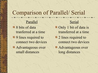
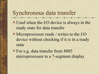
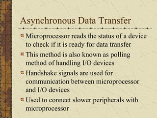
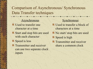
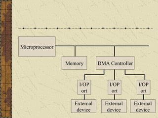
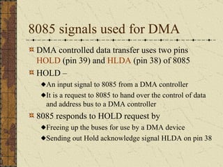
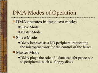
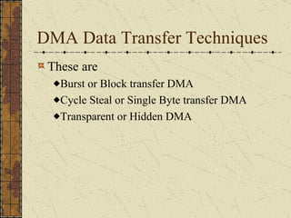
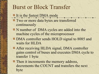
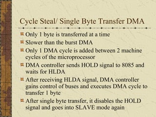
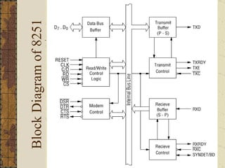
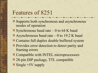
Unit – 2 I/O Memory Interface Topics:  Programmable, Interrupt initiated, DMA, Serial and Parallel Interfaces for data transfer Detailed study of 8251  USART chip
Content Introduction to data transfer techniques Programmed Data Transfer DMA Controlled Data Transfer 8251 USART – A Serial I/O Processor
1.  Introduction to Data Transfer Techniques Data transfer may take place between two devices. For e.g. Microprocessor and memory Microprocessor and I/O device Memory and I/O device Classification of data transfer techniques Programmed data transfer Direct Memory Access (DMA)
2.  Programmed Data Transfer Data is transferred from the I/O device to the microprocessor or memory  Data is transferred under the control of the program stored in the program memory of the microprocessor based system This technique of data transfer is normally used if the size of data to be transferred is small
Programmed data transfer techniques Classified as Parallel data transfer Serial data transfer Synchronous data transfer Asynchronous data transfer Interrupt Initiated data transfer
Parallel Data Transfer All the bits are transferred at the same time Used for data transfer between nearby devices E.g microprocessor and program memory Advantage Data transfer is very fast
Serial data transfer Data is transferred one bit at a time  Suitable for data transfer over long distances E.g. dial-up internet connections using modems Data transfer is slow as compared to parallel data transfer technique
Comparison of Parallel/ Serial Parallel 8 bits of data tranferred at a time 9 lines required to connect two devices Advantageous over small distances Serial Only 1 bit of data is transferred at a time 2 lines required to connect two devices Advantageous over long distances
Synchronous data transfer Used when the I/O device is always in the ready state for data transfer Microprocessor reads / writes to the I/O device without checking if it is in a ready state For e.g. data transfer from 8085 microprocessor to a 7-segment display
Asynchronous Data Transfer Microprocessor reads the status of a device to check if it is ready for data transfer This method is also known as polling method of handling I/O devices Handshake signals are used for communication between microprocessor and I/O devices Used to connect slower peripherals with microprocessor
Comparison of Asynchronous/ Synchronous Data Transfer techniques Asynchronous Used to transfer one character at a time Start and stop bits are used with each character Speed is less Transmitter and receiver can use two separate clock inputs Synchronous Used to transfer a block of characters at a time No start/ stop bits are used Speed is high Transmitter and receiver share a common clock
Interrupt Initiated Data Transfer Microprocessor initiates the interrupt mechanism and starts executing the main program I/O device informs the microprocessor that it is ready by generating an interrupt signal Microprocessor services the interrupt by completing the data transfer
3.  DMA Controlled Data Transfer  DMA stands for Direct Memory Access used when large amount of data is to be transferred Microprocessor does not participate in this type of data transfer Data is transferred directly between an I/O device and memory or vice-versa Data transfer is controlled by an I/O device or a DMA controller DMA data transfer is fast as compared to programmed data transfer
Microprocessor Memory DMA Controller I/OPort I/OPort I/OPort External device External device External device
8085 signals used for DMA DMA controlled data transfer uses two pins  HOLD  (pin 39) and  HLDA  (pin 38) of 8085 HOLD –  An input signal to 8085 from a DMA controller It is a request to 8085 to hand over the control of data and address bus to a DMA controller 8085 responds to HOLD request by Freeing up the buses for use by a DMA device Sending out Hold acknowledge signal HLDA on pin 38
DMA Modes of Operation DMA operates in these two modes Slave Mode Master Mode Slave Mode DMA behaves as a I/O peripheral requesting the microprocessor for the control of the buses Master Mode DMA plays the role of a data transfer processor to peripherals such as floppy disks
DMA Data Transfer Techniques These are  Burst or Block transfer DMA Cycle Steal or Single Byte transfer DMA Transparent or Hidden DMA
Burst or Block Transfer It is the fastest DMA mode Two or more data bytes are transferred continuously N number of  DMA cycles are added into the machine cycles of the microprocessor DMA controller sends HOLD signal to 8085 and waits for HLDA After receiving HLDA signal, DMA controller gains control of buses and executes DMA cycle to transfer 1 byte Then it increments the memory address, decrements the COUNT and transfers the next byte
Cycle Steal/ Single Byte Transfer DMA Only 1 byte is transferred at a time Slower than the burst DMA Only 1 DMA cycle is added between 2 machine cycles of the microprocessor DMA controller sends HOLD signal to 8085 and waits for HLDA After receiving HLDA signal, DMA controller gains control of buses and executes DMA cycle to transfer 1 byte After single byte transfer, it disables the HOLD signal and goes into SLAVE mode again
Transparent or Hidden DMA Microprocessor executes some states during which it floats the address and data buses During these states the microprocessor is isolated from the system bus Transparent or Hidden DMA uses these states to transfer data between memory and I/O devices This type of DMA transfer does not reduce the speed of the microprocessor This is the slowest type of DMA transfer
 
4.  8251 USART – A Serial I/O Processor 8251 is a programmable USART chip designed for Synchronous and Asynchronous serial communication USART stands for Universal Synchronous/ Asynchronous Receiver and Transmitter It is used to implement hardware-controlled serial I/O in a microprocessor based system
How 8085 uses 8251 for serial communication? 8085 initializes 8251 chip by sending some command words to it 8085 sends a 8-bit data value to 8251 for serial data transfer 8251 converts this parallel data into serial stream and transmits on serial output line Similarly, 8251 can receive data on serial input line, converts it to parallel form and then transfers it to 8085 microprocessor
Block Diagram of 8251
Features of 8251 Supports both synchronous and asynchronous modes of operation Synchronous baud rate – 0 to 64 K baud Asynchronous baud rate – 0 to 19.2 K baud Contains full duplex double buffered system Provides error detection to detect parity and framing errors Compatible with INTEL microprocessors 28-pin DIP package, TTL compatible  Single +5V supply
References Chapter – 15,16 of “Microprocessor Architecture, Programming, and Applications with the 8085” by Ramesh Gaonkar Chapter – 10 of “Microprocessor and Assembly Language Programming” by U.S. Shah http://www.electronics.dit.ie/staff/tscarff/8251usart/8251.htm Resources on Chalkpad

Unit – 2

  • 1.
    Unit – 2I/O Memory Interface Topics: Programmable, Interrupt initiated, DMA, Serial and Parallel Interfaces for data transfer Detailed study of 8251 USART chip
  • 2.
    Content Introduction todata transfer techniques Programmed Data Transfer DMA Controlled Data Transfer 8251 USART – A Serial I/O Processor
  • 3.
    1. Introductionto Data Transfer Techniques Data transfer may take place between two devices. For e.g. Microprocessor and memory Microprocessor and I/O device Memory and I/O device Classification of data transfer techniques Programmed data transfer Direct Memory Access (DMA)
  • 4.
    2. ProgrammedData Transfer Data is transferred from the I/O device to the microprocessor or memory Data is transferred under the control of the program stored in the program memory of the microprocessor based system This technique of data transfer is normally used if the size of data to be transferred is small
  • 5.
    Programmed data transfertechniques Classified as Parallel data transfer Serial data transfer Synchronous data transfer Asynchronous data transfer Interrupt Initiated data transfer
  • 6.
    Parallel Data TransferAll the bits are transferred at the same time Used for data transfer between nearby devices E.g microprocessor and program memory Advantage Data transfer is very fast
  • 7.
    Serial data transferData is transferred one bit at a time Suitable for data transfer over long distances E.g. dial-up internet connections using modems Data transfer is slow as compared to parallel data transfer technique
  • 8.
    Comparison of Parallel/Serial Parallel 8 bits of data tranferred at a time 9 lines required to connect two devices Advantageous over small distances Serial Only 1 bit of data is transferred at a time 2 lines required to connect two devices Advantageous over long distances
  • 9.
    Synchronous data transferUsed when the I/O device is always in the ready state for data transfer Microprocessor reads / writes to the I/O device without checking if it is in a ready state For e.g. data transfer from 8085 microprocessor to a 7-segment display
  • 10.
    Asynchronous Data TransferMicroprocessor reads the status of a device to check if it is ready for data transfer This method is also known as polling method of handling I/O devices Handshake signals are used for communication between microprocessor and I/O devices Used to connect slower peripherals with microprocessor
  • 11.
    Comparison of Asynchronous/Synchronous Data Transfer techniques Asynchronous Used to transfer one character at a time Start and stop bits are used with each character Speed is less Transmitter and receiver can use two separate clock inputs Synchronous Used to transfer a block of characters at a time No start/ stop bits are used Speed is high Transmitter and receiver share a common clock
  • 12.
    Interrupt Initiated DataTransfer Microprocessor initiates the interrupt mechanism and starts executing the main program I/O device informs the microprocessor that it is ready by generating an interrupt signal Microprocessor services the interrupt by completing the data transfer
  • 13.
    3. DMAControlled Data Transfer DMA stands for Direct Memory Access used when large amount of data is to be transferred Microprocessor does not participate in this type of data transfer Data is transferred directly between an I/O device and memory or vice-versa Data transfer is controlled by an I/O device or a DMA controller DMA data transfer is fast as compared to programmed data transfer
  • 14.
    Microprocessor Memory DMAController I/OPort I/OPort I/OPort External device External device External device
  • 15.
    8085 signals usedfor DMA DMA controlled data transfer uses two pins HOLD (pin 39) and HLDA (pin 38) of 8085 HOLD – An input signal to 8085 from a DMA controller It is a request to 8085 to hand over the control of data and address bus to a DMA controller 8085 responds to HOLD request by Freeing up the buses for use by a DMA device Sending out Hold acknowledge signal HLDA on pin 38
  • 16.
    DMA Modes ofOperation DMA operates in these two modes Slave Mode Master Mode Slave Mode DMA behaves as a I/O peripheral requesting the microprocessor for the control of the buses Master Mode DMA plays the role of a data transfer processor to peripherals such as floppy disks
  • 17.
    DMA Data TransferTechniques These are Burst or Block transfer DMA Cycle Steal or Single Byte transfer DMA Transparent or Hidden DMA
  • 18.
    Burst or BlockTransfer It is the fastest DMA mode Two or more data bytes are transferred continuously N number of DMA cycles are added into the machine cycles of the microprocessor DMA controller sends HOLD signal to 8085 and waits for HLDA After receiving HLDA signal, DMA controller gains control of buses and executes DMA cycle to transfer 1 byte Then it increments the memory address, decrements the COUNT and transfers the next byte
  • 19.
    Cycle Steal/ SingleByte Transfer DMA Only 1 byte is transferred at a time Slower than the burst DMA Only 1 DMA cycle is added between 2 machine cycles of the microprocessor DMA controller sends HOLD signal to 8085 and waits for HLDA After receiving HLDA signal, DMA controller gains control of buses and executes DMA cycle to transfer 1 byte After single byte transfer, it disables the HOLD signal and goes into SLAVE mode again
  • 20.
    Transparent or HiddenDMA Microprocessor executes some states during which it floats the address and data buses During these states the microprocessor is isolated from the system bus Transparent or Hidden DMA uses these states to transfer data between memory and I/O devices This type of DMA transfer does not reduce the speed of the microprocessor This is the slowest type of DMA transfer
  • 21.
  • 22.
    4. 8251USART – A Serial I/O Processor 8251 is a programmable USART chip designed for Synchronous and Asynchronous serial communication USART stands for Universal Synchronous/ Asynchronous Receiver and Transmitter It is used to implement hardware-controlled serial I/O in a microprocessor based system
  • 23.
    How 8085 uses8251 for serial communication? 8085 initializes 8251 chip by sending some command words to it 8085 sends a 8-bit data value to 8251 for serial data transfer 8251 converts this parallel data into serial stream and transmits on serial output line Similarly, 8251 can receive data on serial input line, converts it to parallel form and then transfers it to 8085 microprocessor
  • 24.
  • 25.
    Features of 8251Supports both synchronous and asynchronous modes of operation Synchronous baud rate – 0 to 64 K baud Asynchronous baud rate – 0 to 19.2 K baud Contains full duplex double buffered system Provides error detection to detect parity and framing errors Compatible with INTEL microprocessors 28-pin DIP package, TTL compatible Single +5V supply
  • 26.
    References Chapter –15,16 of “Microprocessor Architecture, Programming, and Applications with the 8085” by Ramesh Gaonkar Chapter – 10 of “Microprocessor and Assembly Language Programming” by U.S. Shah http://www.electronics.dit.ie/staff/tscarff/8251usart/8251.htm Resources on Chalkpad