Download to read offline
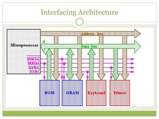
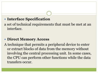
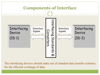
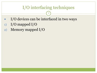
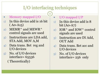
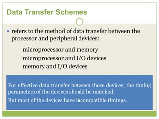
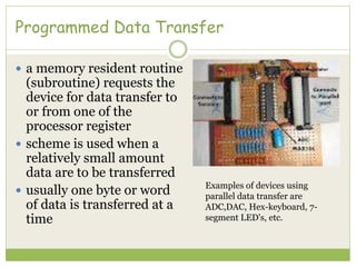

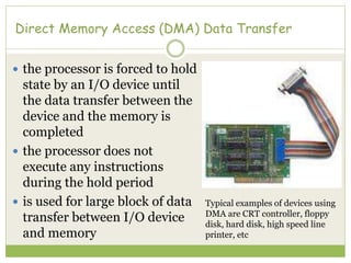
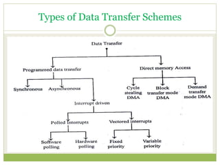
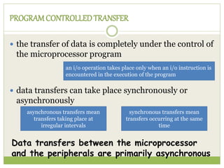
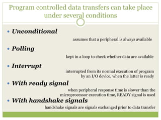
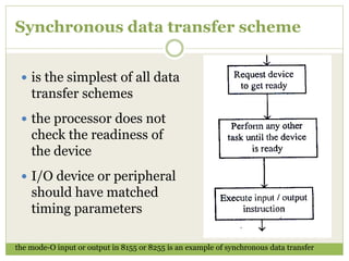
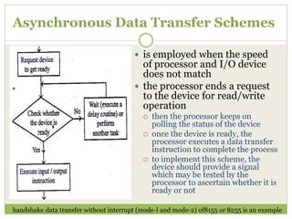
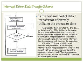
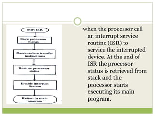
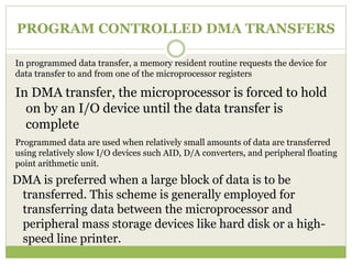
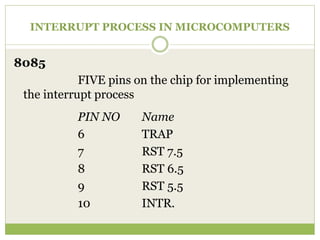

This document discusses interface definitions and data transfer schemes. It defines an interface as a shared boundary between system elements that allows for input/output communication via signals and protocols. Interface devices meet interface specifications on one side. Data transfer schemes refer to the method of transferring data between a processor and peripheral devices, and include programmed and direct memory access transfers. Programmed transfers involve small data amounts using I/O instructions, while direct memory access allows large block transfers without processor involvement.


![[Deck] What's New in Spark-Iceberg Integration via DSV2.pptx](https://cdn.slidesharecdn.com/ss_thumbnails/deckwhatsnewinspark-icebergintegrationviadsv2-260210005337-25955b12-thumbnail.jpg?width=640&height=640&fit=bounds)


