Download to read offline
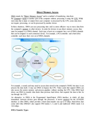


Direct Memory Access (DMA) allows transferring data between computer memory and devices without using the CPU. This saves processing time by allowing devices like sound cards, video cards, and hard drives to access memory directly. DMA channels are assigned to devices to enable direct memory access. Common DMA transfer types include memory-to-memory transfers and auto-initialization, which automatically restores register values after a transfer.


![DMA presentation [By- Digvijay]](https://cdn.slidesharecdn.com/ss_thumbnails/digvijay-dmapresentation-131231041837-phpapp02-thumbnail.jpg?width=640&height=640&fit=bounds)