COMPUTER ORGANIZATION NOTES Unit 3 4
•
2 likes•1,611 views

COMPUTER ORGANIZATION NOTES Unit 3 4

Recommended
More Related Content
What's hot
What's hot (20)
Similar to COMPUTER ORGANIZATION NOTES Unit 3 4
Similar to COMPUTER ORGANIZATION NOTES Unit 3 4 (20)
More from Dr.MAYA NAYAK
More from Dr.MAYA NAYAK (8)
Recently uploaded
Recently uploaded (20)
COMPUTER ORGANIZATION NOTES Unit 3 4
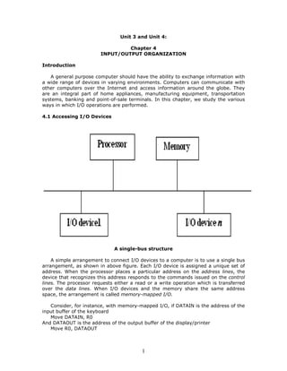
- 1. 1 Unit 3 and Unit 4: Chapter 4 INPUT/OUTPUT ORGANIZATION Introduction A general purpose computer should have the ability to exchange information with a wide range of devices in varying environments. Computers can communicate with other computers over the Internet and access information around the globe. They are an integral part of home appliances, manufacturing equipment, transportation systems, banking and point-of-sale terminals. In this chapter, we study the various ways in which I/O operations are performed. 4.1 Accessing I/O Devices A single-bus structure A simple arrangement to connect I/O devices to a computer is to use a single bus arrangement, as shown in above figure. Each I/O device is assigned a unique set of address. When the processor places a particular address on the address lines, the device that recognizes this address responds to the commands issued on the control lines. The processor requests either a read or a write operation which is transferred over the data lines. When I/O devices and the memory share the same address space, the arrangement is called memory-mapped I/O. Consider, for instance, with memory-mapped I/O, if DATAIN is the address of the input buffer of the keyboard Move DATAIN, R0 And DATAOUT is the address of the output buffer of the display/printer Move R0, DATAOUT
- 2. 2 This sends the contents of register R0 to location DATAOUT, which may be the output data buffer of a display unit or a printer. Most computer systems use memory-mapped I/O. Some processors have special I/O instructions to perform I/O transfers. The hardware required to connect an I/O device to the bus is shown below: I/O interface for an input device The address decoder enables the device to recognize its address when this address appears on the address lines. The data register holds the data. The status register contains information. The address decoder, data and status registers and controls required to coordinate I/O transfers constitutes interface circuit For eg: Keyboard, an instruction that reads a character from the keyboard should be executed only when a character is available in the input buffer of the keyboard interface. The processor repeatedly checks a status flag to achieve the synchronization between processor and I/O device, which is called as program- controlled I/O. Two commonly used mechanisms for implementing I/O operations are: • Interrupts and • Direct memory access Interrupts: synchronization is achieved by having the I/O device send a special signal over the bus whenever it is ready for a data transfer operation. Direct memory access: For high speed I/O devices. The device interface transfer data directly to or from the memory without informing the processor.
- 3. 3 4.2 Interrupts There are many situations where other tasks can be performed while waiting for an I/O device to become ready. A hardware signal called an Interrupt will alert the processor when an I/O device becomes ready. Interrupt-request line is usually dedicated for this purpose. For example, consider, COMPUTE and PRINT routines. The routine executed in response to an interrupt request is called interrupt-service routine. Transfer of control through the use of interrupts happens. The processor must inform the device that its request has been recognized by sending interrupt-acknowledge signal. One must therefore know the difference between Interrupt Vs Subroutine. Interrupt latency is concerned with saving information in registers will increase the delay between the time an interrupt request is received and the start of execution of the interrupt-service routine. Interrupt hardware Most computers have several I/O devices that can request an interrupt. A single interrupt request line may be used to serve n devices. Enabling and Disabling Interrupts All computers fundamentally should be able to enable and disable interruptions as desired. Again reconsider the COMPUTE and PRINT example. When a device activates the interrupt-request signal, it keeps this signal activated until it learns that the processor has accepted its request. When interrupts are enabled, the following is a typical scenario: • The device raises an interrupt request. • The processor interrupts the program currently being executed. • Interrupts are disabled by changing the control bits in the processor status register (PS). • The device is informed that its request has been recognized and deactivates the interrupt request signal. • The action requested by the interrupt is performed by the interrupt-service routine. • Interrupts are enabled and execution of the interrupted program is resumed. Handling multiple devices While handling multiple devices, the issues concerned are: • How can the processor recognize the device requesting an interrupt? • How can the processor obtain the starting address of the appropriate routine? • Should a device be allowed to interrupt the processor while another interrupt is being serviced? • How should two or more simultaneous interrupt requests be handled? Vectored interrupts A device requesting an interrupt may identify itself (by sending a special code) directly to the processor, so that the processor considers it immediately.
- 4. 4 Interrupt nesting The processor should continue to execute the interrupt-service routine till completion, before it accepts an interrupt request from a second device. Privilege exception means they execute privileged instructions. Individual interrupt-request and acknowledge lines can also be implemented. Implementation of interrupt priority using individual interrupt-request and acknowledge lines has been shown in figure 4.7. Simultaneous requests The processor must have some mechanisms to decide which request to service when simultaneous requests arrive. Here, daisy chain and arrangement of priority groups as the interrupt priority schemes are discussed. Priority based simultaneous requests are considered in many organizations. Controlling device requests At the device end, an interrupt enable bit determines whether it is allowed to generate an interrupt request. At the processor end, it determines whether a given interrupt request will be accepted. Exceptions The term exception is used to refer to any event that causes an interruption. Hence, I/O interrupts are one example of an exception. • Recovery from errors – These are techniques to ensure that all hardware components are operating properly. • Debugging – find errors in a program, trace and breakpoints (only at specific points selected by the user). • Privilege exception – execute privileged instructions to protect OS of a computer. Use of interrupts in Operating Systems Operating system is system software which is also termed as resource manager, as it manages all variety of computer peripheral devices efficiently. Different issues addressed by the operating systems are: Assign priorities among jobs, Security and protection features, incorporate interrupt-service routines for all devices and Multitasking, time slice, process, program state, context switch and others. 4.4 Direct Memory Access As we have seen earlier, the two commonly used mechanisms for implementing I/O operations are: • Interrupts and • Direct memory access
- 5. 5 Interrupts: synchronization is achieved by having the I/O device send a special signal over the bus whenever it is ready for a data transfer operation Direct memory access: Basically for high speed I/O devices, the device interface transfer data directly to or from the memory without informing the processor. When interrupts are used, additional overhead involved with saving and restoring the program counter and other state information. To transfer large blocks of data at high speed, an alternative approach is used. A special control unit will allow transfer of a block of data directly between an external device and the main memory, without continuous intervention by the processor. DMA controller is a control circuit that performs DMA transfers, is a part of the I/O device interface. It performs functions that normally be carried out by the processor. DMA controller must increment the memory address and keep track of the number of transfers. The operations of DMA controller must be under the control of a program executed by the processor. To initiate the transfer of block of words, the processor sends the starting address, the number of words in the block and the direction of the transfer. On receiving this information, DMA controller transfers the entire block and informs the processor by raising an interrupt signal. While a DMA transfer is taking place, the processor can be used to execute another program. After the DMA transfer is completed, the processor can return to the program that requested the transfer. • Three registers in a DMA interface are: • Starting address • Word count • Status and control flag Use of DMA controllers in a computer system A conflict may arise if both the processor and a DMA controller or two DMA controllers try to use the bus at the same time to access the main memory. To resolve this, an arbitration procedure is implemented on the bus to coordinate the activities of all devices requesting memory transfers.
- 6. 6 Bus Arbitration The device that is allowed to initiate data transfers on the bus at any given time is called the bus master. Arbitration is the process by which the next device to become the bus master is selected and bus mastership is transferred to it. The two approaches are centralized and distributed arbitrations. In centralized, a single bus arbiter performs the required arbitration whereas in distributed, all device participate in the selection of the next bus master. The bus arbiter may be the processor or a separate unit connected to the bus. The processor is normally the bus master unless it grants bus mastership to one of the DMA controllers. A simple arrangement for bus arbitration using daisy chain and a distributed arbitration scheme are discussed in figure 4.20 and 4.22 respectively. In Centralized arbitration, A simple arrangement for bus arbitration using a daisy chain shows the arbitration solution. A rotating priority scheme may be used to give all devices an equal chance of being serviced (BR1 to BR4). In Distributed arbitration, all devices waiting to use the bus have equal responsibility in carrying out the arbitration process, without using a central arbiter. The drivers are of the open-collector type. Hence, if the input to one driver is equal to 1 and the input to another driver connected to the same bus line is equal to 0 the bus will be in the low-voltage state. This uses ARB0 to ARB3. 4.5 Buses The Primary function of the bus is to provide a communication path for the transfer of data. It must also look in to, – When to place information on the bus? – When to have control signals? Some bus protocols are set. These involve data, address and control lines. A variety of schemes have been devised for the timing of data transfers over a bus. They are: Synchronous and Asynchronous schemes Bus master is an initiator. Usually, processor acts as master. But under DMA setup, any other device can be master. The device addressed by the master is slave or target. Synchronous bus All devices derive timing information from a common clock line. Equally spaced pulses on this line define equal time intervals. Each of these intervals constitutes a bus cycle during which one data transfer can take place. Timing of an input/output transfer on a synchronous bus is shown in figure 4.23. Asynchronous bus This is a scheme based on the use of a handshake between the master and the slave for controlling data transfers on the bus. The common clock is replaced by two timing control lines, master-ready and slave-ready. The first is asserted by the master to indicate that it is ready for a transaction and the second is a response from the slave. The master places the address and command information on the bus. It indicates to all devices that it has done so by activating the master-ready line. This
- 7. 7 causes all devices on the bus to decode the address. The selected slave performs the required operation and informs the processor it has done so by activating the slave- ready line. A typical handshake control of data transfer during an input and an output operations are shown in figure 4.26 and 4.27 respectively. The master waits for slave-ready to become asserted before it removes its signals from the bus. The handshake signals are fully interlocked. A change of state in one signal is followed by a change in the other signal. Hence this scheme is known as a full handshake. 4.6 Interface Circuits An I/O interface consists of the circuitry required to connect an I/O device to a computer bus. On one side of the interface, we have bus signals. On the other side, we have a data path with its associated controls to transfer data between the interface and the I/O device – port. We have two types: Serial port and Parallel port A parallel port transfers data in the form of a number of bits (8 or 16) simultaneously to or from the device. A serial port transmits and receives data one bit at a time. Communication with the bus is the same for both formats. The conversion from the parallel to the serial format, and vice versa, takes place inside the interface circuit. In parallel port, the connection between the device and the computer uses a multiple-pin connector and a cable with as many wires. This arrangement is suitable for devices that are physically close to the computer. In serial port, it is much more convenient and cost-effective where longer cables are needed. Typically, the functions of an I/O interface are: • Provides a storage buffer for at least one word of data • Contains status flags that can be accessed by the processor to determine whether the buffer is full or empty • Contains address-decoding circuitry to determine when it is being addressed by the processor • Generates the appropriate timing signals required by the bus control scheme • Performs any format conversion that may be necessary to transfer data between the bus and the I/O device, such as parallel-serial conversion in the case of a serial port Parallel Port The hardware components needed for connecting a keyboard to a processor Consider the circuit of input interface which encompasses (as shown in below figure): – Status flag, SIN – R/~W – Master-ready – Address decoder A detailed figure showing the input interface circuit is presented in figure 4.29. Now, consider the circuit for the status flag (figure 4.30). An edge-triggered D flip-flop is used along with read-data and master-ready signals.
- 8. 8 Keyboard to processor connection Printer to processor connection The hardware components needed for connecting a printer to a processor are: the circuit of output interface, and – Slave-ready – R/~W – Master-ready – Address decoder – Handshake control
- 9. 9 The input and output interfaces can be combined into a single interface. The general purpose parallel interface circuit that can be configured in a variety of ways. For increased flexibility, the circuit makes it possible for some lines to serve as inputs and some lines to serve as outputs, under program control. Serial Port A serial interface circuit involves – Chip and register select, Status and control, Output shift register, DATAOUT, DATAIN, Input shift register and Serial input/output – as shown in figure 4.37. 4.7 Standard I/O interfaces Consider a computer system using different interface standards. Let us look in to Processor bus and Peripheral Component Interconnect (PCI) bus. These two buses are interconnected by a circuit called bridge. It is a bridge between processor bus and PCI bus. An example of a computer system using different interface standards is shown in figure 4.38. The three major standard I/O interfaces discussed here are: – PCI (Peripheral Component Interconnect) – SCSI (Small Computer System Interface) – USB (Universal Serial Bus) PCI (Peripheral Component Interconnect) The topics discussed under PCI are: Data Transfer, Use of a PCI bus in a computer system, A read operation on the PCI bus, Device configuration and Other electrical characteristics. Use of a PCI bus in a computer system is shown in figure 4.39 as a representation. Host, main memory and PCI bridge are connected to disk, printer and Ethernet interface through PCI bus. At any given time, one device is the bus master. It has the right to initiate data transfers by issuing read and write commands. A master is called an initiator in PCI terminology. This is either processor or DMA controller. The addressed device that responds to read and write commands is called a target. A complete transfer operation on the bus, involving an address and a burst of data, is called a transaction. Device configuration is also discussed. SCSI Bus It is a standard bus defined by the American National Standards Institute (ANSI). A controller connected to a SCSI bus is an initiator or a target. The processor sends a command to the SCSI controller, which causes the following sequence of events to take place: • The SCSI controller contends for control of the bus (initiator). • When the initiator wins the arbitration process, it selects the target controller and hands over control of the bus to it. • The target starts an output operation. The initiator sends a command specifying the required read operation. • The target sends a message to the initiator indicating that it will temporarily suspends the connection between them. Then it releases the bus.
- 10. 10 • The target controller sends a command to the disk drive to move the read head to the first sector involved in the requested read operation. • The target transfers the contents of the data buffer to the initiator and then suspends the connection again. • The target controller sends a command to the disk drive to perform another seek operation. • As the initiator controller receives the data, it stores them into the main memory using the DMA approach. • The SCSI controller sends an interrupt to the processor to inform it that the requested operation has been completed. The bus signals, arbitration, selection, information transfer and reselection are the topics discussed in addition to the above. Universal Serial Bus (USB) The USB has been designed to meet several key objectives such as: • Provide a simple, low-cost and easy to use interconnection system that overcomes the difficulties due to the limited number of I/O ports available on a computer • Accommodate a wide range of data transfer characteristics for I/O devices, including telephone and Internet connections • Enhance user convenience through a “plug-and-play” mode of operation Port Limitation Here to add new ports, a user must open the computer box to gain access to the internal expansion bus and install a new interface card. The user may also need to know how to configure the device and the software. And also it is to make it possible to add many devices to a computer system at any time, without opening the computer box. Device Characteristics The kinds of devices that may be connected to a computer cover a wide range of functionality - speed, volume and timing constraints. A variety of simple devices attached to a computer generate data in different asynchronous mode. A signal must be sampled quickly enough to track its highest-frequency components. Plug-and-play Whenever a device is introduced, do not turn the computer off/restart to connect/disconnect a device. The system should detect the existence of this new device automatically, identify the appropriate device-driver software and any other facilities needed to service that device, and establish the appropriate addresses and logical connections to enable them to communicate. USB architecture To accommodate a large number of devices that can be added or removed at any time, the USB has the tree structure. Each node has a device called a hub. Root hub, functions, split bus operations – high speed (HS) and Full/Low speed (F/LS).
- 11. 11 4.8 Concluding remarks The three basic approaches of I/O transfers are discussed. The simplest technique is programmed I/O, in which the processor performs all the necessary control functions under direct control of program instructions. The second approach is based on the use of interrupts. The third I/O scheme involves DMA, the DMA controller transfers data between an I/O device and the main memory without continuous processor intervention. Access to memory is shared between the DMAQ controller and the processor. Three popular interconnection standards – PCI, SCSI, USB are discussed. They represent different approaches that meet the needs of various devices and reflect the increasing importance of plug-and-ply features that increase user convenience. Reference: Carl Hamacher, Zvonko Vranesic, Safwat Zaky, Computer Organization, fifth edition, Mc-graw Hill higher education.