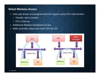
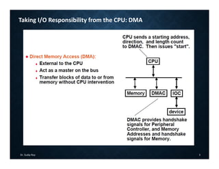
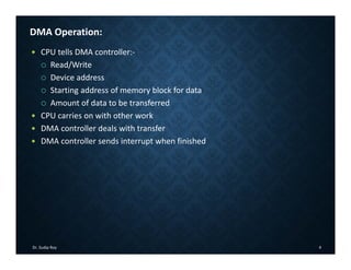
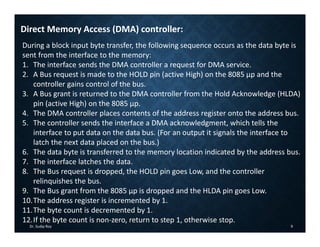
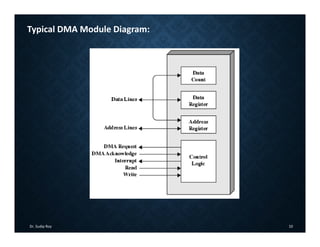
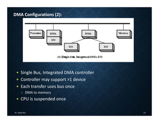
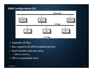
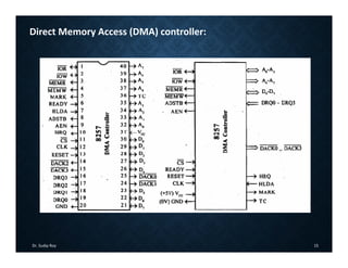
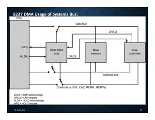
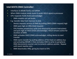
Course Website: http://faculty.iitr.ac.in/~sudiproy.fcs/csn221_2015.html
Piazza Site: https://piazza.com/iitr.ac.in/fall2015/csn221
Dr. Sudip Roy
CSN‐221: COMPUTER ARCHITECTURE
AND MICROPROCESSORS
Input/Output (I/O) Devices
(Lecture – 36)
Dr. Sudip Roy 2
Direct Memory Access:
 Interrupt driven and programmed I/O require active CPU intervention
 Transfer rate is limited
 CPU is tied up
 Additional Module (hardware) on bus
 DMA controller takes over from CPU for I/O
Dr. Sudip Roy 3
Taking I/O Responsibility from the CPU: DMA
Dr. Sudip Roy 4
DMA Operation:
 CPU tells DMA controller:‐
 Read/Write
 Device address
 Starting address of memory block for data
 Amount of data to be transferred
 CPU carries on with other work
 DMA controller deals with transfer
 DMA controller sends interrupt when finished
Dr. Sudip Roy 5
Direct Memory Access (DMA) transfer:
 When the processor needs to be accessed again and again to perform a
repeated data copying operation, then
 to save time & power, control of the data transfer lines is given to the
input device controller
 HOLD & HLDA are used for this process
 HOLD is sent from I/O device to the processor asking for control of the data
lines
 HLDA is sent from processor to the I/O device acknowledging the transfer of
the control of the data lines.
Dr. Sudip Roy 6
Direct Memory Access (DMA) transfer:
 DMA is an IO technique where external IO device requests the use of the
MPU buses.
 Allows external IO devices to gain high speed access to the memory.
 Example of IO devices that use DMA: disk memory system.
 If HOLD=1, 8085 will place it address, data and control pins at their high‐
impedance.
 A DMA acknowledgement is signaled by HLDA=1.
 In DMA, there are 2 modes
 Burst Mode
 Cycle stealing
Dr. Sudip Roy 7
DMA: HOLD and HLDA
HLDA
HLDA
Dr. Sudip Roy 8
Direct Memory Access (DMA) controller:
Dr. Sudip Roy 9
Direct Memory Access (DMA) controller:
During a block input byte transfer, the following sequence occurs as the data byte is
sent from the interface to the memory:
1. The interface sends the DMA controller a request for DMA service.
2. A Bus request is made to the HOLD pin (active High) on the 8085 µp and the
controller gains control of the bus.
3. A Bus grant is returned to the DMA controller from the Hold Acknowledge (HLDA)
pin (active High) on the 8085 µp.
4. The DMA controller places contents of the address register onto the address bus.
5. The controller sends the interface a DMA acknowledgment, which tells the
interface to put data on the data bus. (For an output it signals the interface to
latch the next data placed on the bus.)
6. The data byte is transferred to the memory location indicated by the address bus.
7. The interface latches the data.
8. The Bus request is dropped, the HOLD pin goes Low, and the controller
relinquishes the bus.
9. The Bus grant from the 8085 µp is dropped and the HLDA pin goes Low.
10.The address register is incremented by 1.
11.The byte count is decremented by 1.
12.If the byte count is non‐zero, return to step 1, otherwise stop.
Dr. Sudip Roy 10
Typical DMA Module Diagram:
Dr. Sudip Roy 11
DMA Transfer: Cycle Stealing
 DMA controller takes over bus for a cycle
 Transfer of one word of data
 Not an interrupt
 CPU does not switch context
 CPU suspended just before it accesses bus
 i.e., before an operand or data fetch or a data write
 Slows down CPU but not as much as CPU doing transfer
Dr. Sudip Roy 12
DMA Configurations (1):
 Single Bus, Detached DMA controller
 Each transfer uses bus twice
 I/O to DMA then DMA to memory
 CPU is suspended twice
Dr. Sudip Roy 13
DMA Configurations (2):
 Single Bus, Integrated DMA controller
 Controller may support >1 device
 Each transfer uses bus once
 DMA to memory
 CPU is suspended once
Dr. Sudip Roy 14
DMA Configurations (3):
 Separate I/O Bus
 Bus supports all DMA enabled devices
 Each transfer uses bus once
 DMA to memory
 CPU is suspended once
Dr. Sudip Roy 15
Direct Memory Access (DMA) controller:
Dr. Sudip Roy 16
8237 DMA Usage of Systems Bus:
Dr. Sudip Roy 17
Intel 8237A DMA Controller:
 Interfaces to 80x86 family and DRAM
 When DMA module needs buses it sends HOLD signal to processor
 CPU responds HLDA (hold acknowledge)
 DMA module can use buses
 E.g. transfer data from memory to disk
1. Device requests service of DMA by pulling DREQ (DMA request) high
2. DMA puts high on HRQ (hold request)
3. CPU finishes present bus cycle (not necessarily present instruction)
and puts high on HDLA (hold acknowledge). HOLD remains active for
duration of DMA
4. DMA activates DACK (DMA acknowledge), telling device to start
transfer
5. DMA starts transfer by putting address of first byte on address bus
and activating MEMR; it then activates IOW to write to peripheral.
DMA decrements counter and increments address pointer. Repeat
until count reaches zero
6. DMA deactivates HRQ, giving bus back to CPU
Dr. Sudip Roy 18
Mode of Data Transfer:
Dr. Sudip Roy 19
Serial and Parallel Communication:
Dr. Sudip Roy 20
Data Communication: Serial vs. Parallel
Dr. Sudip Roy 21
Type of Serial Communications:
Dr. Sudip Roy 22
Format of Serial Communications:
Dr. Sudip Roy 23
Format of Serial Communications:
Dr. Sudip Roy 24
Type of Serial Communications:
Stop bits
Dr. Sudip Roy 25
Framing in Asynchronous:

CSN221_Lec_36 Computer Architecture and Microprocessor

  • 1.
    Course Website: http://faculty.iitr.ac.in/~sudiproy.fcs/csn221_2015.html PiazzaSite: https://piazza.com/iitr.ac.in/fall2015/csn221 Dr. Sudip Roy CSN‐221: COMPUTER ARCHITECTURE AND MICROPROCESSORS Input/Output (I/O) Devices (Lecture – 36)
  • 2.
    Dr. Sudip Roy2 Direct Memory Access:  Interrupt driven and programmed I/O require active CPU intervention  Transfer rate is limited  CPU is tied up  Additional Module (hardware) on bus  DMA controller takes over from CPU for I/O
  • 3.
    Dr. Sudip Roy3 Taking I/O Responsibility from the CPU: DMA
  • 4.
    Dr. Sudip Roy4 DMA Operation:  CPU tells DMA controller:‐  Read/Write  Device address  Starting address of memory block for data  Amount of data to be transferred  CPU carries on with other work  DMA controller deals with transfer  DMA controller sends interrupt when finished
  • 5.
    Dr. Sudip Roy5 Direct Memory Access (DMA) transfer:  When the processor needs to be accessed again and again to perform a repeated data copying operation, then  to save time & power, control of the data transfer lines is given to the input device controller  HOLD & HLDA are used for this process  HOLD is sent from I/O device to the processor asking for control of the data lines  HLDA is sent from processor to the I/O device acknowledging the transfer of the control of the data lines.
  • 6.
    Dr. Sudip Roy6 Direct Memory Access (DMA) transfer:  DMA is an IO technique where external IO device requests the use of the MPU buses.  Allows external IO devices to gain high speed access to the memory.  Example of IO devices that use DMA: disk memory system.  If HOLD=1, 8085 will place it address, data and control pins at their high‐ impedance.  A DMA acknowledgement is signaled by HLDA=1.  In DMA, there are 2 modes  Burst Mode  Cycle stealing
  • 7.
    Dr. Sudip Roy7 DMA: HOLD and HLDA HLDA HLDA
  • 8.
    Dr. Sudip Roy8 Direct Memory Access (DMA) controller:
  • 9.
    Dr. Sudip Roy9 Direct Memory Access (DMA) controller: During a block input byte transfer, the following sequence occurs as the data byte is sent from the interface to the memory: 1. The interface sends the DMA controller a request for DMA service. 2. A Bus request is made to the HOLD pin (active High) on the 8085 µp and the controller gains control of the bus. 3. A Bus grant is returned to the DMA controller from the Hold Acknowledge (HLDA) pin (active High) on the 8085 µp. 4. The DMA controller places contents of the address register onto the address bus. 5. The controller sends the interface a DMA acknowledgment, which tells the interface to put data on the data bus. (For an output it signals the interface to latch the next data placed on the bus.) 6. The data byte is transferred to the memory location indicated by the address bus. 7. The interface latches the data. 8. The Bus request is dropped, the HOLD pin goes Low, and the controller relinquishes the bus. 9. The Bus grant from the 8085 µp is dropped and the HLDA pin goes Low. 10.The address register is incremented by 1. 11.The byte count is decremented by 1. 12.If the byte count is non‐zero, return to step 1, otherwise stop.
  • 10.
    Dr. Sudip Roy10 Typical DMA Module Diagram:
  • 11.
    Dr. Sudip Roy11 DMA Transfer: Cycle Stealing  DMA controller takes over bus for a cycle  Transfer of one word of data  Not an interrupt  CPU does not switch context  CPU suspended just before it accesses bus  i.e., before an operand or data fetch or a data write  Slows down CPU but not as much as CPU doing transfer
  • 12.
    Dr. Sudip Roy12 DMA Configurations (1):  Single Bus, Detached DMA controller  Each transfer uses bus twice  I/O to DMA then DMA to memory  CPU is suspended twice
  • 13.
    Dr. Sudip Roy13 DMA Configurations (2):  Single Bus, Integrated DMA controller  Controller may support >1 device  Each transfer uses bus once  DMA to memory  CPU is suspended once
  • 14.
    Dr. Sudip Roy14 DMA Configurations (3):  Separate I/O Bus  Bus supports all DMA enabled devices  Each transfer uses bus once  DMA to memory  CPU is suspended once
  • 15.
    Dr. Sudip Roy15 Direct Memory Access (DMA) controller:
  • 16.
    Dr. Sudip Roy16 8237 DMA Usage of Systems Bus:
  • 17.
    Dr. Sudip Roy17 Intel 8237A DMA Controller:  Interfaces to 80x86 family and DRAM  When DMA module needs buses it sends HOLD signal to processor  CPU responds HLDA (hold acknowledge)  DMA module can use buses  E.g. transfer data from memory to disk 1. Device requests service of DMA by pulling DREQ (DMA request) high 2. DMA puts high on HRQ (hold request) 3. CPU finishes present bus cycle (not necessarily present instruction) and puts high on HDLA (hold acknowledge). HOLD remains active for duration of DMA 4. DMA activates DACK (DMA acknowledge), telling device to start transfer 5. DMA starts transfer by putting address of first byte on address bus and activating MEMR; it then activates IOW to write to peripheral. DMA decrements counter and increments address pointer. Repeat until count reaches zero 6. DMA deactivates HRQ, giving bus back to CPU
  • 18.
    Dr. Sudip Roy18 Mode of Data Transfer:
  • 19.
    Dr. Sudip Roy19 Serial and Parallel Communication:
  • 20.
    Dr. Sudip Roy20 Data Communication: Serial vs. Parallel
  • 21.
    Dr. Sudip Roy21 Type of Serial Communications:
  • 22.
    Dr. Sudip Roy22 Format of Serial Communications:
  • 23.
    Dr. Sudip Roy23 Format of Serial Communications:
  • 24.
    Dr. Sudip Roy24 Type of Serial Communications: Stop bits
  • 25.
    Dr. Sudip Roy25 Framing in Asynchronous: