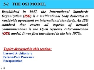
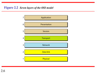
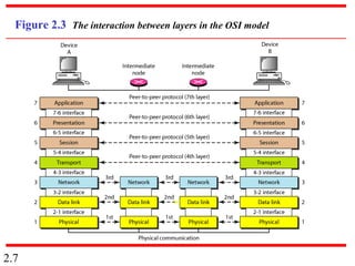
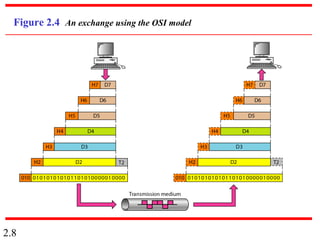
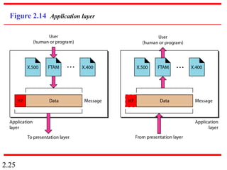
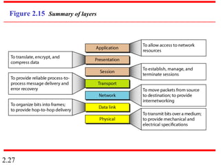
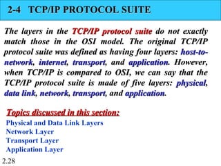
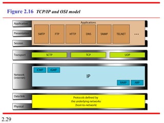
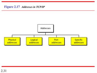
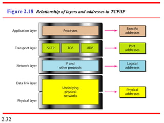
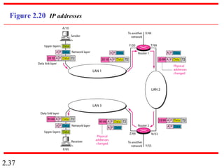
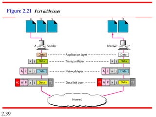
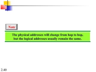
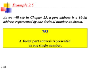
SlideShare a Scribd company logo
1 of 42
2.1
Chapter 2
Network Models
Copyright © The McGraw-Hill Companies, Inc. Permission required for reproduction or display.
2.2
2-1 LAYERED TASKS2-1 LAYERED TASKS
We use the concept ofWe use the concept of layerslayers in our daily life. As anin our daily life. As an
example, let us consider two friends who communicateexample, let us consider two friends who communicate
through postal mail. The process of sending a letter to athrough postal mail. The process of sending a letter to a
friend would be complex if there were no servicesfriend would be complex if there were no services
available from the post office.available from the post office.
Sender, Receiver, and Carrier
Hierarchy
Topics discussed in this section:Topics discussed in this section:
2.3
Figure 2.1 Tasks involved in sending a letter
2.4
2-2 THE OSI MODEL2-2 THE OSI MODEL
Established in 1947, the International StandardsEstablished in 1947, the International Standards
Organization (Organization (ISOISO) is a multinational body dedicated to) is a multinational body dedicated to
worldwide agreement on international standards. An ISOworldwide agreement on international standards. An ISO
standard that covers all aspects of networkstandard that covers all aspects of network
communications is the Open Systems Interconnectioncommunications is the Open Systems Interconnection
((OSIOSI) model. It was first introduced in the late 1970s.) model. It was first introduced in the late 1970s.
Layered Architecture
Peer-to-Peer Processes
Encapsulation
Topics discussed in this section:Topics discussed in this section:
2.5
ISO is the organization.
OSI is the model.
Note
2.6
Figure 2.2 Seven layers of the OSI model
2.7
Figure 2.3 The interaction between layers in the OSI model
2.8
Figure 2.4 An exchange using the OSI model
2.9
2-3 LAYERS IN THE OSI MODEL2-3 LAYERS IN THE OSI MODEL
In this section we briefly describe the functions of eachIn this section we briefly describe the functions of each
layer in the OSI model.layer in the OSI model.
Physical Layer
Data Link Layer
Network Layer
Transport Layer
Session Layer
Presentation Layer
Application Layer
Topics discussed in this section:Topics discussed in this section:
2.10
Figure 2.5 Physical layer
2.11
The physical layer is responsible for movements of
individual bits from one hop (node) to the next.
Note
2.12
Figure 2.6 Data link layer
2.13
The data link layer is responsible for moving
frames from one hop (node) to the next.
Note
2.14
Figure 2.7 Hop-to-hop delivery
2.15
Figure 2.8 Network layer
2.16
The network layer is responsible for the
delivery of individual packets from
the source host to the destination host.
Note
2.17
Figure 2.9 Source-to-destination delivery
2.18
Figure 2.10 Transport layer
2.19
The transport layer is responsible for the delivery
of a message from one process to another.
Note
2.20
Figure 2.11 Reliable process-to-process delivery of a message
2.21
Figure 2.12 Session layer
2.22
The session layer is responsible for dialog
control and synchronization.
Note
2.23
Figure 2.13 Presentation layer
2.24
The presentation layer is responsible for translation,
compression, and encryption.
Note
2.25
Figure 2.14 Application layer
2.26
The application layer is responsible for
providing services to the user.
Note
2.27
Figure 2.15 Summary of layers
2.28
2-4 TCP/IP PROTOCOL SUITE2-4 TCP/IP PROTOCOL SUITE
The layers in theThe layers in the TCP/IP protocol suiteTCP/IP protocol suite do not exactlydo not exactly
match those in the OSI model. The original TCP/IPmatch those in the OSI model. The original TCP/IP
protocol suite was defined as having four layers:protocol suite was defined as having four layers: host-to-host-to-
networknetwork,, internetinternet,, transporttransport, and, and applicationapplication. However,. However,
when TCP/IP is compared to OSI, we can say that thewhen TCP/IP is compared to OSI, we can say that the
TCP/IP protocol suite is made of five layers:TCP/IP protocol suite is made of five layers: physicalphysical,,
data linkdata link,, networknetwork,, transporttransport, and, and applicationapplication..
Physical and Data Link Layers
Network Layer
Transport Layer
Application Layer
Topics discussed in this section:Topics discussed in this section:
2.29
Figure 2.16 TCP/IP and OSI model
2.30
2-5 ADDRESSING2-5 ADDRESSING
Four levels of addresses are used in an internet employingFour levels of addresses are used in an internet employing
the TCP/IP protocols:the TCP/IP protocols: physicalphysical,, logicallogical,, portport, and, and specificspecific..
Physical Addresses
Logical Addresses
Port Addresses
Specific Addresses
Topics discussed in this section:Topics discussed in this section:
2.31
Figure 2.17 Addresses in TCP/IP
2.32
Figure 2.18 Relationship of layers and addresses in TCP/IP
2.33
In Figure 2.19 a node with physical address 10 sends a
frame to a node with physical address 87. The two nodes
are connected by a link (bus topology LAN). As the
figure shows, the computer with physical address 10 is
the sender, and the computer with physical address 87 is
the receiver.
Example 2.1
2.34
Figure 2.19 Physical addresses
2.35
As we will see in Chapter 13, most local-area networks
use a 48-bit (6-byte) physical address written as 12
hexadecimal digits; every byte (2 hexadecimal digits) is
separated by a colon, as shown below:
Example 2.2
07:01:02:01:2C:4B
A 6-byte (12 hexadecimal digits) physical address.
2.36
Figure 2.20 shows a part of an internet with two routers
connecting three LANs. Each device (computer or
router) has a pair of addresses (logical and physical) for
each connection. In this case, each computer is
connected to only one link and therefore has only one
pair of addresses. Each router, however, is connected to
three networks (only two are shown in the figure). So
each router has three pairs of addresses, one for each
connection.
Example 2.3
2.37
Figure 2.20 IP addresses
2.38
Figure 2.21 shows two computers communicating via
the Internet. The sending computer is running three
processes at this time with port addresses a, b, and c. The
receiving computer is running two processes at this time
with port addresses j and k. Process a in the sending
computer needs to communicate with process j in the
receiving computer. Note that although physical
addresses change from hop to hop, logical and port
addresses remain the same from the source to
destination.
Example 2.4
2.39
Figure 2.21 Port addresses
2.40
The physical addresses will change from hop to hop,
but the logical addresses usually remain the same.
Note
2.41
Example 2.5
As we will see in Chapter 23, a port address is a 16-bit
address represented by one decimal number as shown.
753
A 16-bit port address represented
as one single number.
2.42
The physical addresses change from hop to hop,
but the logical and port addresses usually remain the same.
Note

More Related Content

What's hot (19)

1b network models
1b network models1b network models
1b network models
 
Ch02
Ch02Ch02
Ch02
 
Chapter 2 - Network Models
Chapter 2 - Network ModelsChapter 2 - Network Models
Chapter 2 - Network Models
 
Unit 1 network models & typical examples(part a)
Unit 1 network models & typical examples(part a)Unit 1 network models & typical examples(part a)
Unit 1 network models & typical examples(part a)
 
Ch2 v1
Ch2 v1Ch2 v1
Ch2 v1
 
Computer Network - Chapter 2
Computer Network - Chapter 2Computer Network - Chapter 2
Computer Network - Chapter 2
 
Ch02
Ch02Ch02
Ch02
 
Ch2 v1
Ch2 v1Ch2 v1
Ch2 v1
 
Ch1 v1
Ch1 v1Ch1 v1
Ch1 v1
 
Chapter 2: Network Models
Chapter 2: Network ModelsChapter 2: Network Models
Chapter 2: Network Models
 
Ch2 network models
Ch2 network modelsCh2 network models
Ch2 network models
 
Ch 02
Ch 02Ch 02
Ch 02
 
02 Network Models
02 Network Models02 Network Models
02 Network Models
 
Chap 03
Chap 03Chap 03
Chap 03
 
01 Introduction (CN)
01 Introduction (CN)01 Introduction (CN)
01 Introduction (CN)
 
computer communication networks MCQs
 computer communication networks MCQs   computer communication networks MCQs
computer communication networks MCQs
 
Networking models tcp
Networking models tcpNetworking models tcp
Networking models tcp
 
Chapter 4 v6.11
Chapter 4 v6.11Chapter 4 v6.11
Chapter 4 v6.11
 
Chapter 3 v6.01
Chapter 3 v6.01Chapter 3 v6.01
Chapter 3 v6.01
 

Viewers also liked

Viewers also liked (14)

Tcpip 1
Tcpip 1Tcpip 1
Tcpip 1
 
Ip addressing classless
Ip addressing classlessIp addressing classless
Ip addressing classless
 
2
22
2
 
uptu web technology unit 2 html
uptu web technology unit 2 htmluptu web technology unit 2 html
uptu web technology unit 2 html
 
Ip addressing classful
Ip addressing classfulIp addressing classful
Ip addressing classful
 
Rip ospf and bgp
Rip ospf and bgpRip ospf and bgp
Rip ospf and bgp
 
Multicasting and multicast routing protocols
Multicasting and multicast routing protocolsMulticasting and multicast routing protocols
Multicasting and multicast routing protocols
 
Computer network : models and topologies
Computer network : models and topologiesComputer network : models and topologies
Computer network : models and topologies
 
Data Warehousing Practical for T.Y.I.T.
Data Warehousing Practical for T.Y.I.T.Data Warehousing Practical for T.Y.I.T.
Data Warehousing Practical for T.Y.I.T.
 
TYBSC IT SEM 6 IPR/CL
TYBSC IT SEM 6 IPR/CLTYBSC IT SEM 6 IPR/CL
TYBSC IT SEM 6 IPR/CL
 
TYBSC IT SEM 6 PROJECT MANAGEMENT NOTES
TYBSC IT SEM 6 PROJECT MANAGEMENT NOTESTYBSC IT SEM 6 PROJECT MANAGEMENT NOTES
TYBSC IT SEM 6 PROJECT MANAGEMENT NOTES
 
TCP-IP Reference Model
TCP-IP Reference ModelTCP-IP Reference Model
TCP-IP Reference Model
 
Icmp
IcmpIcmp
Icmp
 
Ppt on internet
Ppt on internetPpt on internet
Ppt on internet
 

Similar to 1 (20)

Chapter 2
Chapter 2Chapter 2
Chapter 2
 
Lec2_CH02.PPT
Lec2_CH02.PPTLec2_CH02.PPT
Lec2_CH02.PPT
 
Data Communications and Networking ch02
Data Communications and Networking  ch02Data Communications and Networking  ch02
Data Communications and Networking ch02
 
Ch02
Ch02Ch02
Ch02
 
ch2_v1.ppt
ch2_v1.pptch2_v1.ppt
ch2_v1.ppt
 
dcn 2.ppt
dcn 2.pptdcn 2.ppt
dcn 2.ppt
 
ANAND1.ppt
ANAND1.pptANAND1.ppt
ANAND1.ppt
 
ch2_v1.ppt
ch2_v1.pptch2_v1.ppt
ch2_v1.ppt
 
ch2_v1.ppt
ch2_v1.pptch2_v1.ppt
ch2_v1.ppt
 
Network.ppt
Network.pptNetwork.ppt
Network.ppt
 
ch2_Network Model , layered task, OSI model
ch2_Network Model  , layered task, OSI modelch2_Network Model  , layered task, OSI model
ch2_Network Model , layered task, OSI model
 
Model Jaringan network jaringan komputer.pdf
Model Jaringan network jaringan komputer.pdfModel Jaringan network jaringan komputer.pdf
Model Jaringan network jaringan komputer.pdf
 
All about Network Models under Data Communications
All about Network Models under Data CommunicationsAll about Network Models under Data Communications
All about Network Models under Data Communications
 
ch2_v1.ppt
ch2_v1.pptch2_v1.ppt
ch2_v1.ppt
 
ch2_v1.pptx
ch2_v1.pptxch2_v1.pptx
ch2_v1.pptx
 
Chapter-2.pdf
Chapter-2.pdfChapter-2.pdf
Chapter-2.pdf
 
ch02.ppt
ch02.pptch02.ppt
ch02.ppt
 
Network Models.ppt
Network Models.pptNetwork Models.ppt
Network Models.ppt
 
L2_Networks_OSI_TCP_IP.pptx
L2_Networks_OSI_TCP_IP.pptxL2_Networks_OSI_TCP_IP.pptx
L2_Networks_OSI_TCP_IP.pptx
 
ch02.ppt
ch02.pptch02.ppt
ch02.ppt
 

More from Abhishek Kesharwani (20)

uptu web technology unit 2 html
uptu web technology unit 2 htmluptu web technology unit 2 html
uptu web technology unit 2 html
 
uptu web technology unit 2 html
uptu web technology unit 2 htmluptu web technology unit 2 html
uptu web technology unit 2 html
 
uptu web technology unit 2 html
uptu web technology unit 2 htmluptu web technology unit 2 html
uptu web technology unit 2 html
 
uptu web technology unit 2 html
uptu web technology unit 2 htmluptu web technology unit 2 html
uptu web technology unit 2 html
 
uptu web technology unit 2 Css
uptu web technology unit 2 Cssuptu web technology unit 2 Css
uptu web technology unit 2 Css
 
uptu web technology unit 2 Css
uptu web technology unit 2 Cssuptu web technology unit 2 Css
uptu web technology unit 2 Css
 
uptu web technology unit 2 Xml2
uptu web technology unit 2 Xml2uptu web technology unit 2 Xml2
uptu web technology unit 2 Xml2
 
uptu web technology unit 2 Xml2
uptu web technology unit 2 Xml2uptu web technology unit 2 Xml2
uptu web technology unit 2 Xml2
 
uptu web technology unit 2 Xml2
uptu web technology unit 2 Xml2uptu web technology unit 2 Xml2
uptu web technology unit 2 Xml2
 
uptu web technology unit 2 Xml2
uptu web technology unit 2 Xml2uptu web technology unit 2 Xml2
uptu web technology unit 2 Xml2
 
Unit 1 web technology uptu slide
Unit 1 web technology uptu slideUnit 1 web technology uptu slide
Unit 1 web technology uptu slide
 
Unit1 Web Technology UPTU UNIT 1
Unit1 Web Technology UPTU UNIT 1 Unit1 Web Technology UPTU UNIT 1
Unit1 Web Technology UPTU UNIT 1
 
Unit1 2
Unit1 2 Unit1 2
Unit1 2
 
Web Technology UPTU UNIT 1
Web Technology UPTU UNIT 1 Web Technology UPTU UNIT 1
Web Technology UPTU UNIT 1
 
Mtech syllabus computer science uptu
Mtech syllabus computer science uptu Mtech syllabus computer science uptu
Mtech syllabus computer science uptu
 
Wi max tutorial
Wi max tutorialWi max tutorial
Wi max tutorial
 
Virtual lan
Virtual lanVirtual lan
Virtual lan
 
Virtual lan
Virtual lanVirtual lan
Virtual lan
 
Tcp traffic control and red ecn
Tcp traffic control and red ecnTcp traffic control and red ecn
Tcp traffic control and red ecn
 
Schedulling
SchedullingSchedulling
Schedulling
 

1

  • 1. 2.1 Chapter 2 Network Models Copyright © The McGraw-Hill Companies, Inc. Permission required for reproduction or display.
  • 2. 2.2 2-1 LAYERED TASKS2-1 LAYERED TASKS We use the concept ofWe use the concept of layerslayers in our daily life. As anin our daily life. As an example, let us consider two friends who communicateexample, let us consider two friends who communicate through postal mail. The process of sending a letter to athrough postal mail. The process of sending a letter to a friend would be complex if there were no servicesfriend would be complex if there were no services available from the post office.available from the post office. Sender, Receiver, and Carrier Hierarchy Topics discussed in this section:Topics discussed in this section:
  • 3. 2.3 Figure 2.1 Tasks involved in sending a letter
  • 4. 2.4 2-2 THE OSI MODEL2-2 THE OSI MODEL Established in 1947, the International StandardsEstablished in 1947, the International Standards Organization (Organization (ISOISO) is a multinational body dedicated to) is a multinational body dedicated to worldwide agreement on international standards. An ISOworldwide agreement on international standards. An ISO standard that covers all aspects of networkstandard that covers all aspects of network communications is the Open Systems Interconnectioncommunications is the Open Systems Interconnection ((OSIOSI) model. It was first introduced in the late 1970s.) model. It was first introduced in the late 1970s. Layered Architecture Peer-to-Peer Processes Encapsulation Topics discussed in this section:Topics discussed in this section:
  • 5. 2.5 ISO is the organization. OSI is the model. Note
  • 6. 2.6 Figure 2.2 Seven layers of the OSI model
  • 7. 2.7 Figure 2.3 The interaction between layers in the OSI model
  • 8. 2.8 Figure 2.4 An exchange using the OSI model
  • 9. 2.9 2-3 LAYERS IN THE OSI MODEL2-3 LAYERS IN THE OSI MODEL In this section we briefly describe the functions of eachIn this section we briefly describe the functions of each layer in the OSI model.layer in the OSI model. Physical Layer Data Link Layer Network Layer Transport Layer Session Layer Presentation Layer Application Layer Topics discussed in this section:Topics discussed in this section:
  • 11. 2.11 The physical layer is responsible for movements of individual bits from one hop (node) to the next. Note
  • 12. 2.12 Figure 2.6 Data link layer
  • 13. 2.13 The data link layer is responsible for moving frames from one hop (node) to the next. Note
  • 16. 2.16 The network layer is responsible for the delivery of individual packets from the source host to the destination host. Note
  • 19. 2.19 The transport layer is responsible for the delivery of a message from one process to another. Note
  • 20. 2.20 Figure 2.11 Reliable process-to-process delivery of a message
  • 22. 2.22 The session layer is responsible for dialog control and synchronization. Note
  • 24. 2.24 The presentation layer is responsible for translation, compression, and encryption. Note
  • 26. 2.26 The application layer is responsible for providing services to the user. Note
  • 28. 2.28 2-4 TCP/IP PROTOCOL SUITE2-4 TCP/IP PROTOCOL SUITE The layers in theThe layers in the TCP/IP protocol suiteTCP/IP protocol suite do not exactlydo not exactly match those in the OSI model. The original TCP/IPmatch those in the OSI model. The original TCP/IP protocol suite was defined as having four layers:protocol suite was defined as having four layers: host-to-host-to- networknetwork,, internetinternet,, transporttransport, and, and applicationapplication. However,. However, when TCP/IP is compared to OSI, we can say that thewhen TCP/IP is compared to OSI, we can say that the TCP/IP protocol suite is made of five layers:TCP/IP protocol suite is made of five layers: physicalphysical,, data linkdata link,, networknetwork,, transporttransport, and, and applicationapplication.. Physical and Data Link Layers Network Layer Transport Layer Application Layer Topics discussed in this section:Topics discussed in this section:
  • 29. 2.29 Figure 2.16 TCP/IP and OSI model
  • 30. 2.30 2-5 ADDRESSING2-5 ADDRESSING Four levels of addresses are used in an internet employingFour levels of addresses are used in an internet employing the TCP/IP protocols:the TCP/IP protocols: physicalphysical,, logicallogical,, portport, and, and specificspecific.. Physical Addresses Logical Addresses Port Addresses Specific Addresses Topics discussed in this section:Topics discussed in this section:
  • 32. 2.32 Figure 2.18 Relationship of layers and addresses in TCP/IP
  • 33. 2.33 In Figure 2.19 a node with physical address 10 sends a frame to a node with physical address 87. The two nodes are connected by a link (bus topology LAN). As the figure shows, the computer with physical address 10 is the sender, and the computer with physical address 87 is the receiver. Example 2.1
  • 35. 2.35 As we will see in Chapter 13, most local-area networks use a 48-bit (6-byte) physical address written as 12 hexadecimal digits; every byte (2 hexadecimal digits) is separated by a colon, as shown below: Example 2.2 07:01:02:01:2C:4B A 6-byte (12 hexadecimal digits) physical address.
  • 36. 2.36 Figure 2.20 shows a part of an internet with two routers connecting three LANs. Each device (computer or router) has a pair of addresses (logical and physical) for each connection. In this case, each computer is connected to only one link and therefore has only one pair of addresses. Each router, however, is connected to three networks (only two are shown in the figure). So each router has three pairs of addresses, one for each connection. Example 2.3
  • 37. 2.37 Figure 2.20 IP addresses
  • 38. 2.38 Figure 2.21 shows two computers communicating via the Internet. The sending computer is running three processes at this time with port addresses a, b, and c. The receiving computer is running two processes at this time with port addresses j and k. Process a in the sending computer needs to communicate with process j in the receiving computer. Note that although physical addresses change from hop to hop, logical and port addresses remain the same from the source to destination. Example 2.4
  • 40. 2.40 The physical addresses will change from hop to hop, but the logical addresses usually remain the same. Note
  • 41. 2.41 Example 2.5 As we will see in Chapter 23, a port address is a 16-bit address represented by one decimal number as shown. 753 A 16-bit port address represented as one single number.
  • 42. 2.42 The physical addresses change from hop to hop, but the logical and port addresses usually remain the same. Note