Downloaded 1,067 times
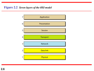
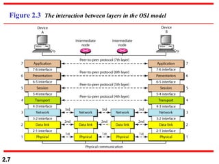
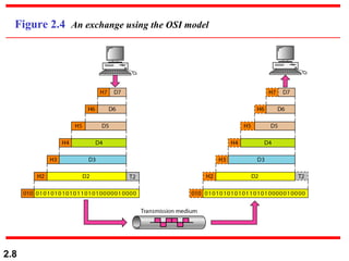
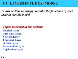
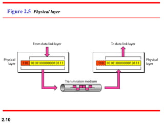

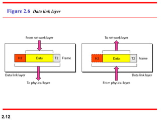
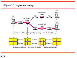
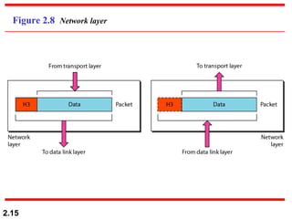
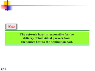
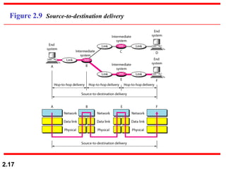
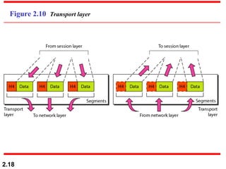
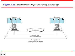
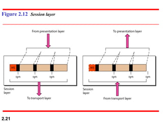
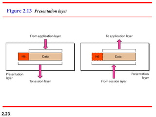
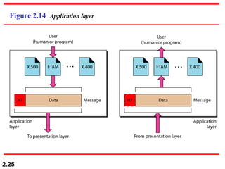
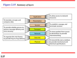
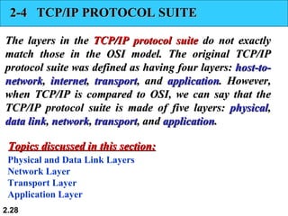
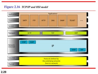
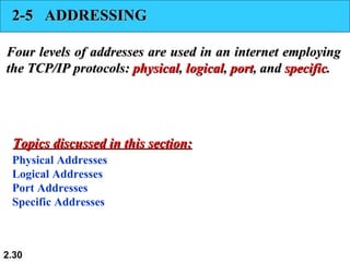
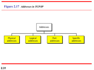
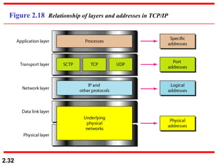
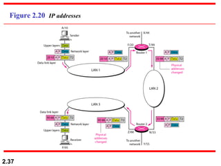
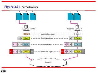
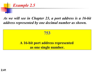

The document discusses network models including the OSI model and TCP/IP protocol suite. The OSI model has 7 layers - physical, data link, network, transport, session, presentation, and application layers. Each layer has a specific function in communication. Similarly, the TCP/IP protocol suite has 5 layers that correspond to the OSI layers - physical, data link, network, transport, and application. The document also discusses different types of addresses used in networking including physical, logical, port, and specific addresses.