Downloaded 618 times


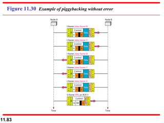
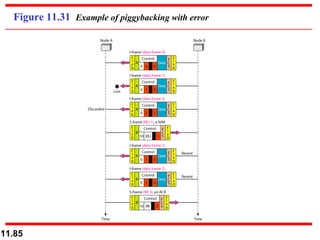
![Figure 11.30 shows an exchange using piggybacking. Node A begins the exchange of information with an I-frame numbered 0 followed by another I-frame numbered 1. Node B piggybacks its acknowledgment of both frames onto an I-frame of its own. Node B’s first I-frame is also numbered 0 [N(S) field] and contains a 2 in its N(R) field, acknowledging the receipt of A’s frames 1 and 0 and indicating that it expects frame 2 to arrive next. Node B transmits its second and third I-frames (numbered 1 and 2) before accepting further frames from node A. Example 11.10](https://image.slidesharecdn.com/ch11-120112060305-phpapp02/85/Chapter-11-81-320.jpg)
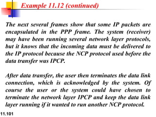
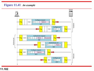
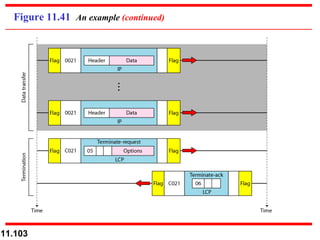

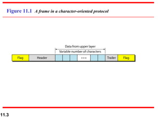
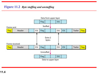
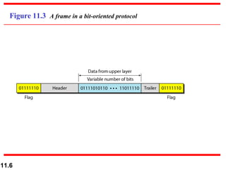
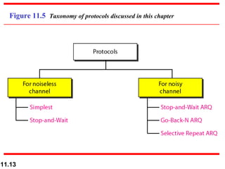
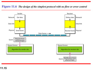
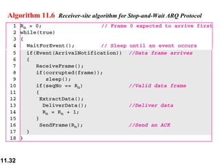
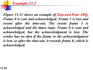
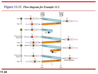
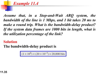
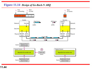
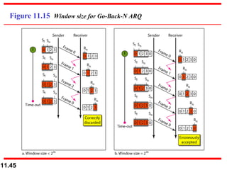
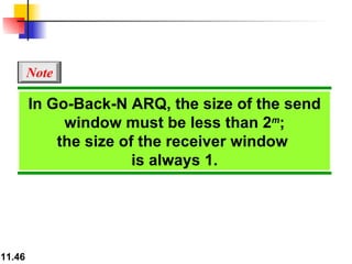
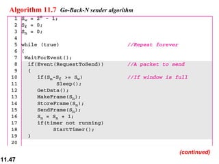
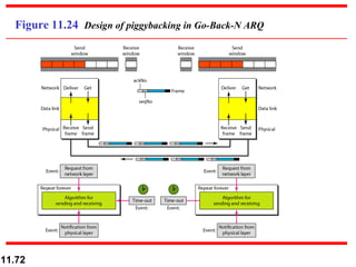
The document discusses various data link layer protocols including framing, flow control, error control, Stop-and-Wait, Go-Back-N, Selective Repeat ARQ, HDLC, and PPP. It provides algorithms and examples to illustrate how each protocol handles framing, flow control, and error correction over both noiseless and noisy channels. Key aspects covered include sequence numbers, acknowledgments, timers, windows, and retransmission methods.