Download as PDF, PPTX
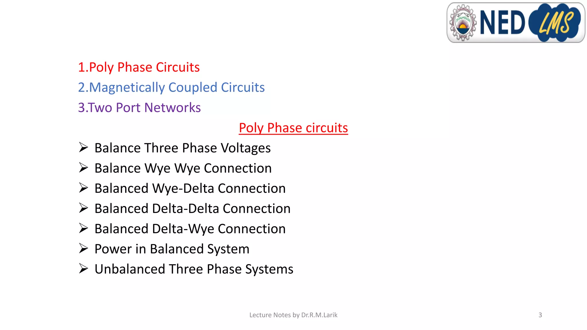
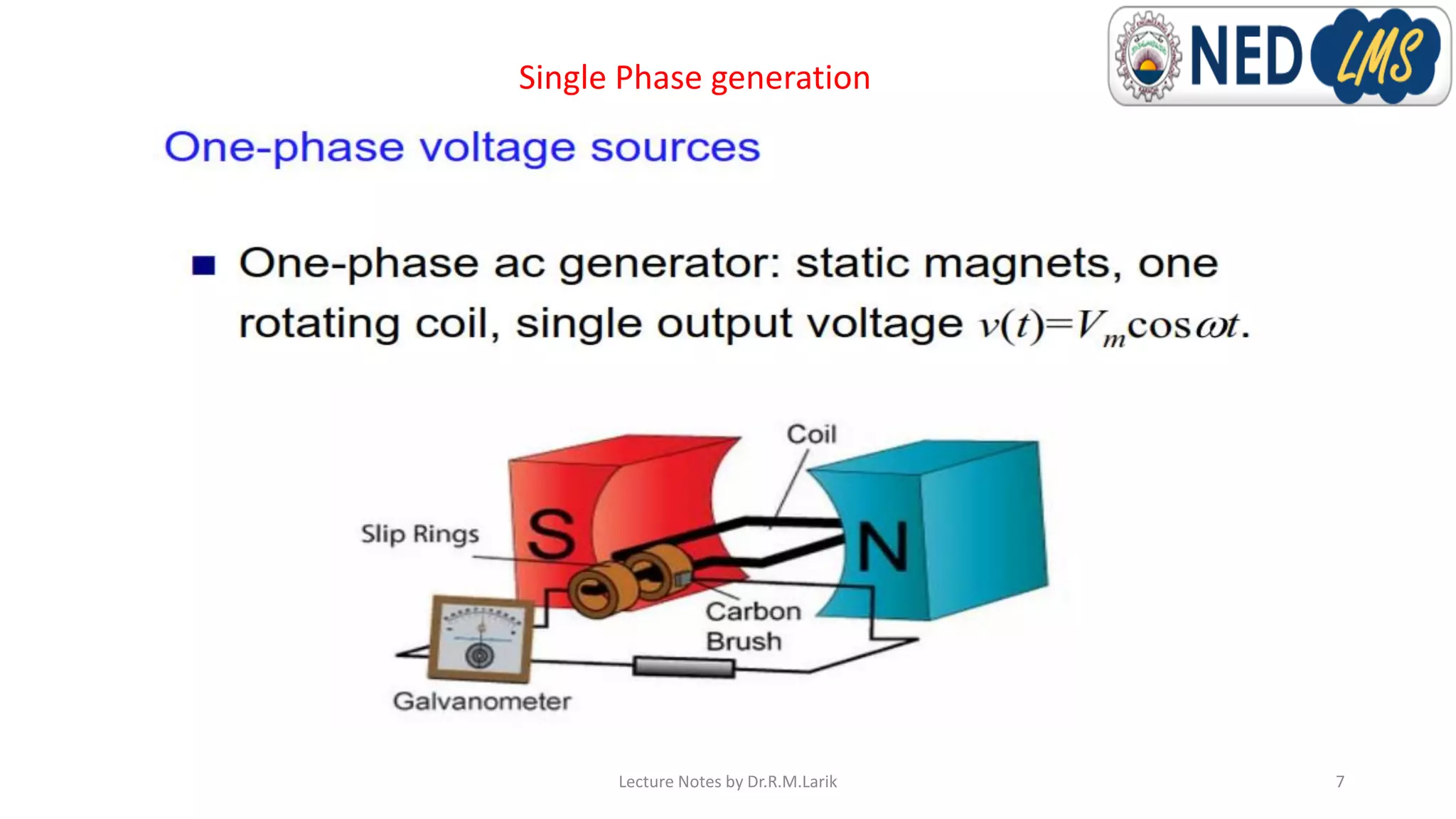
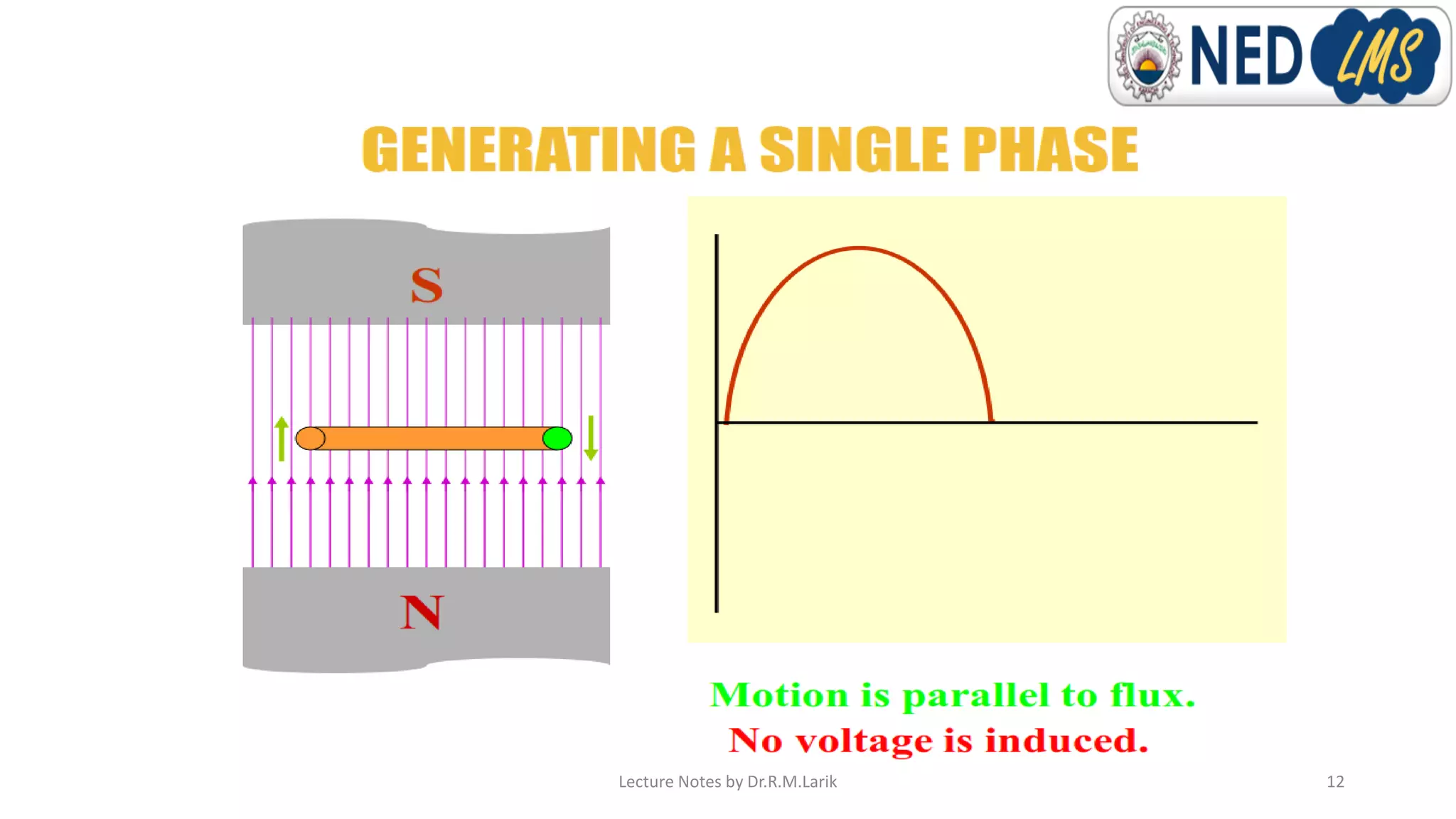
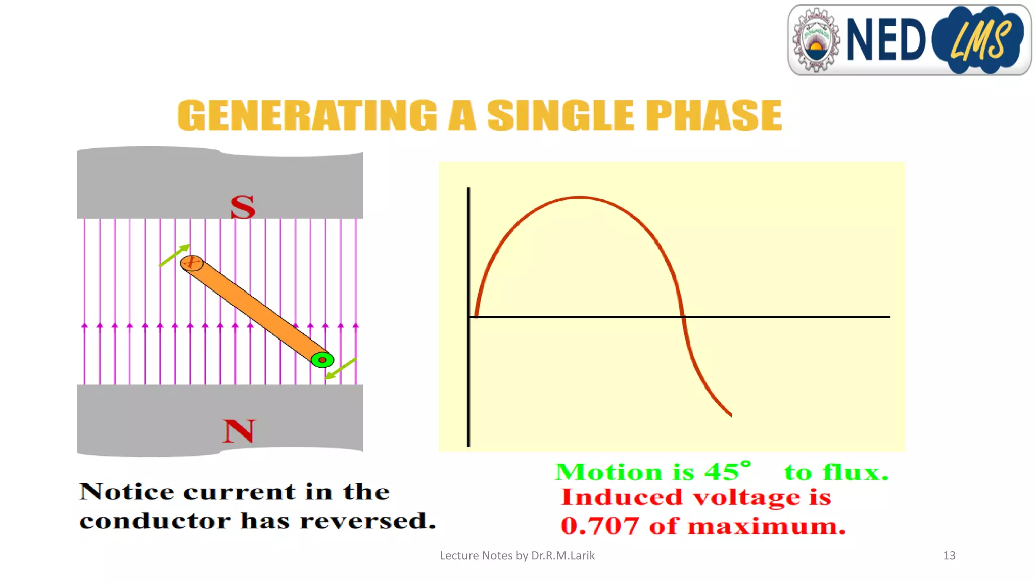
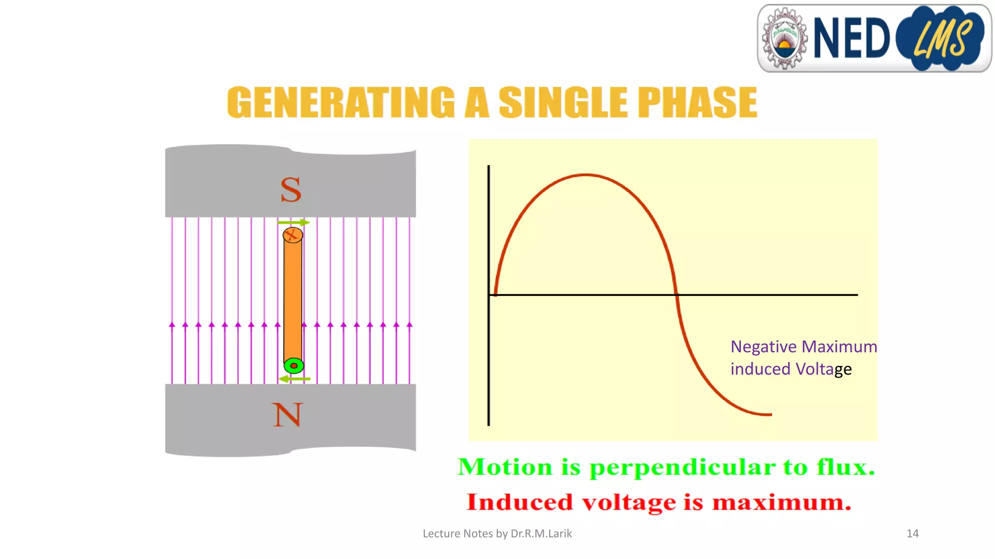
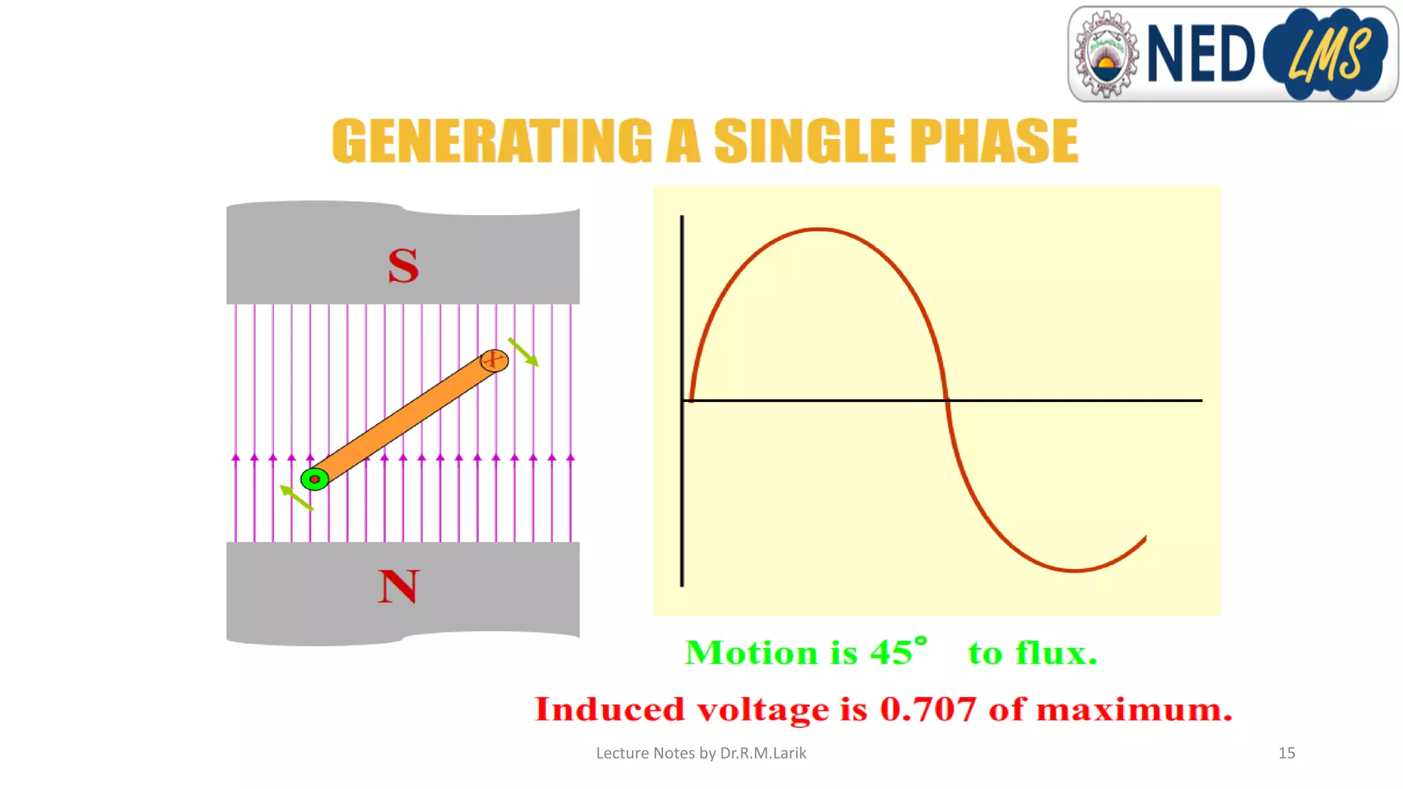
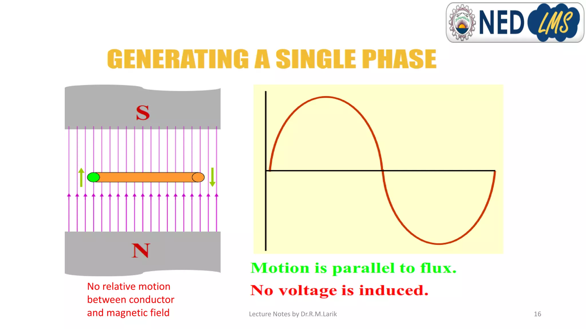
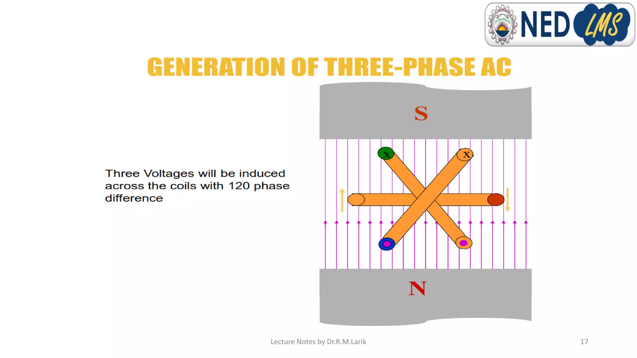
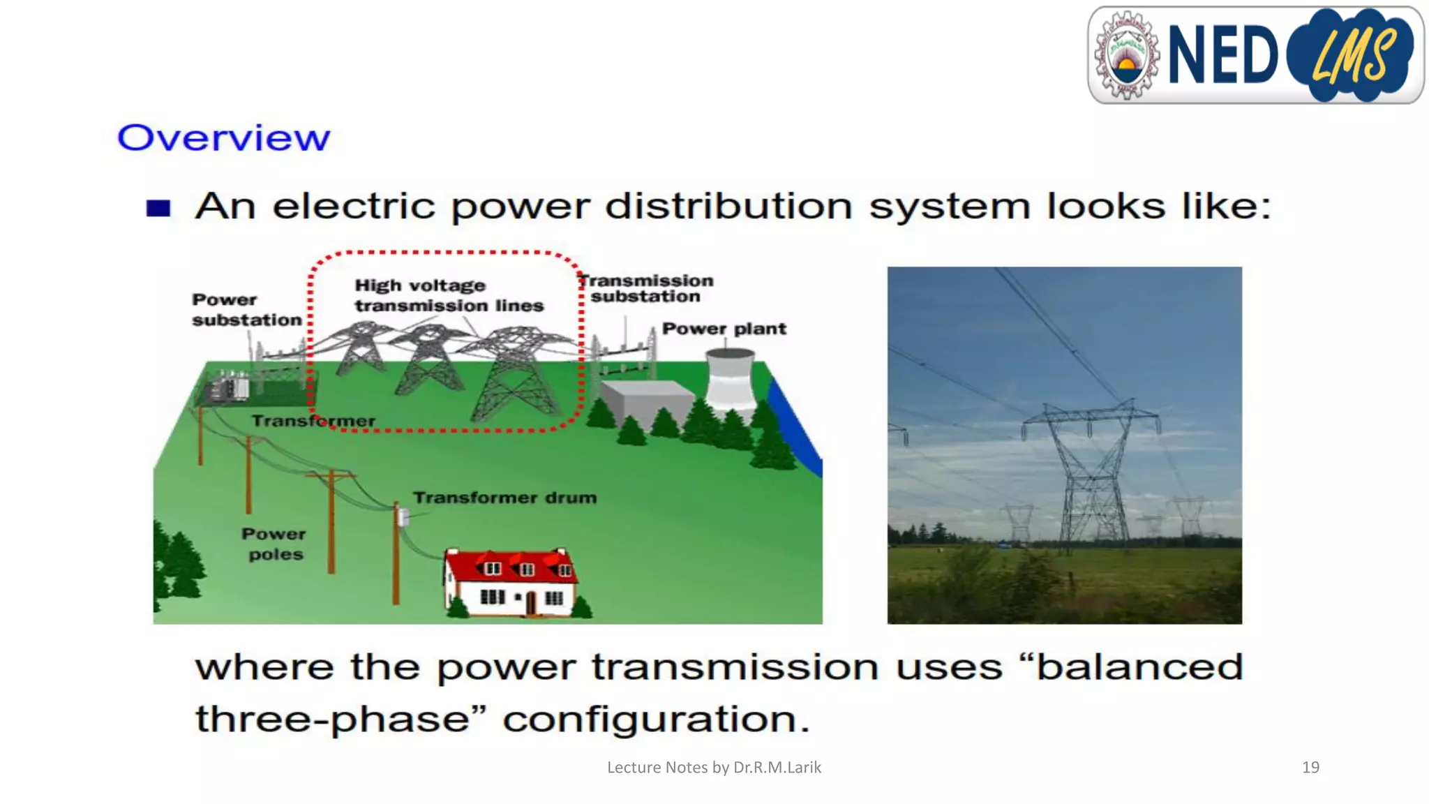
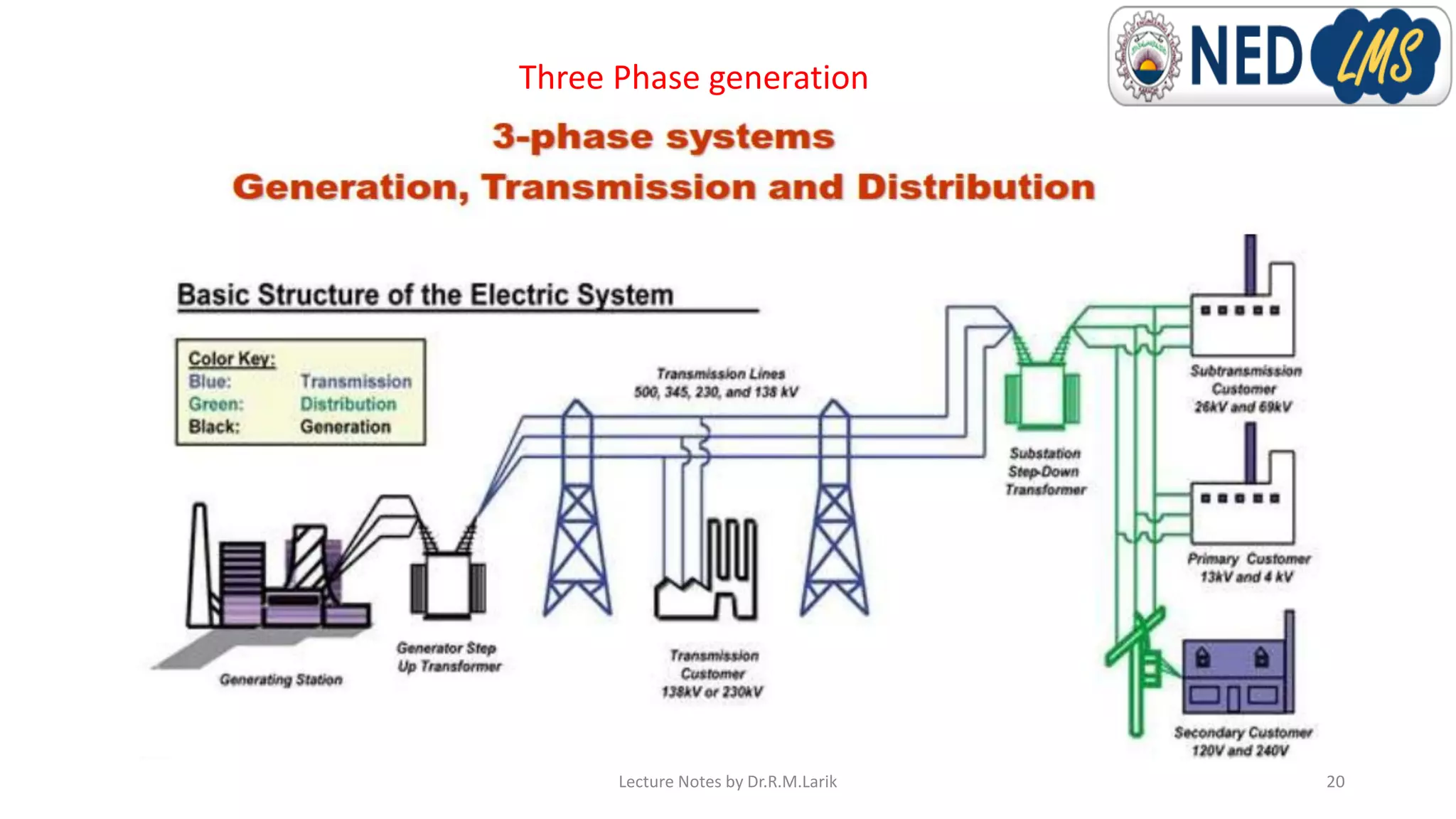
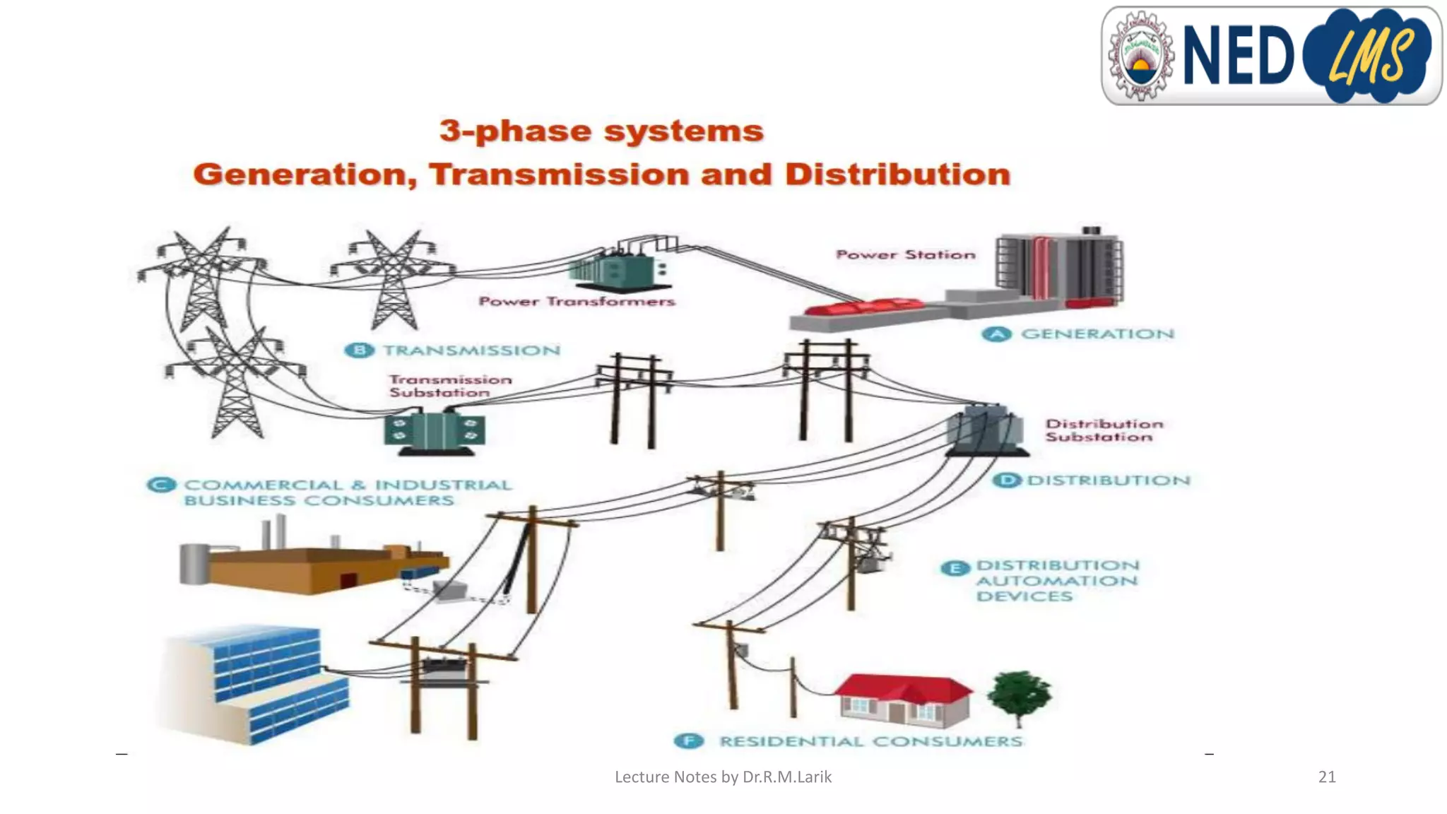
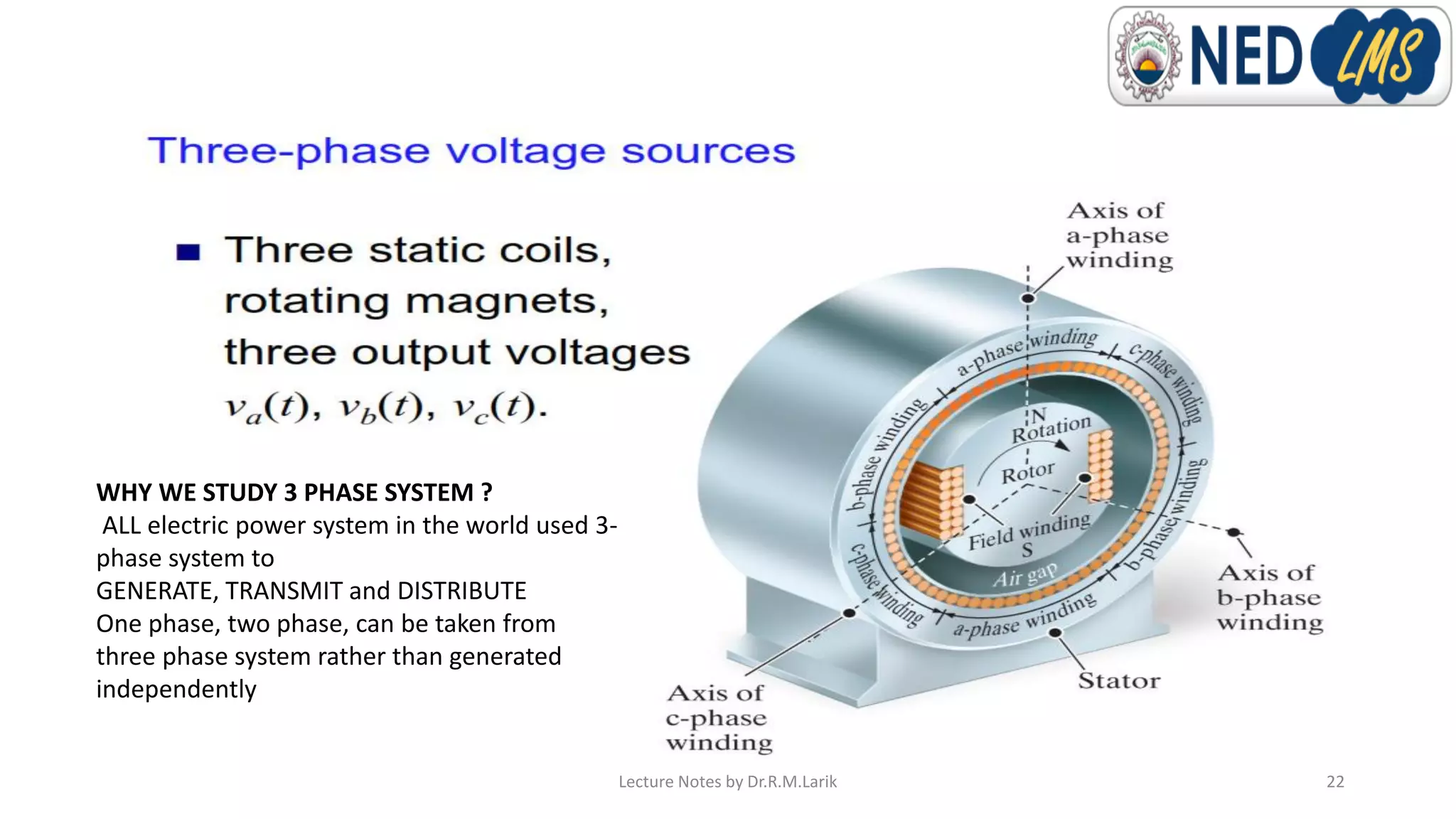
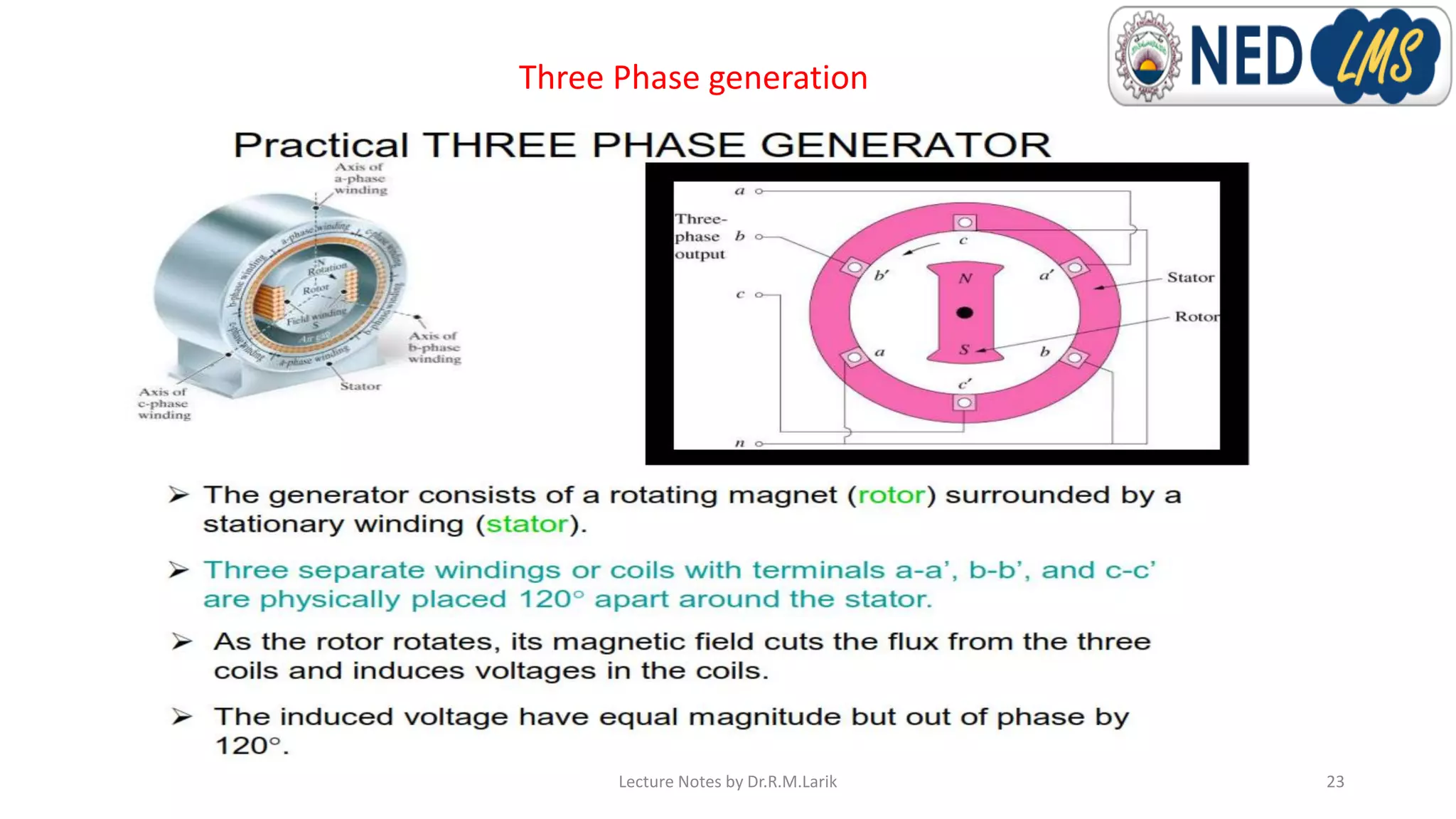
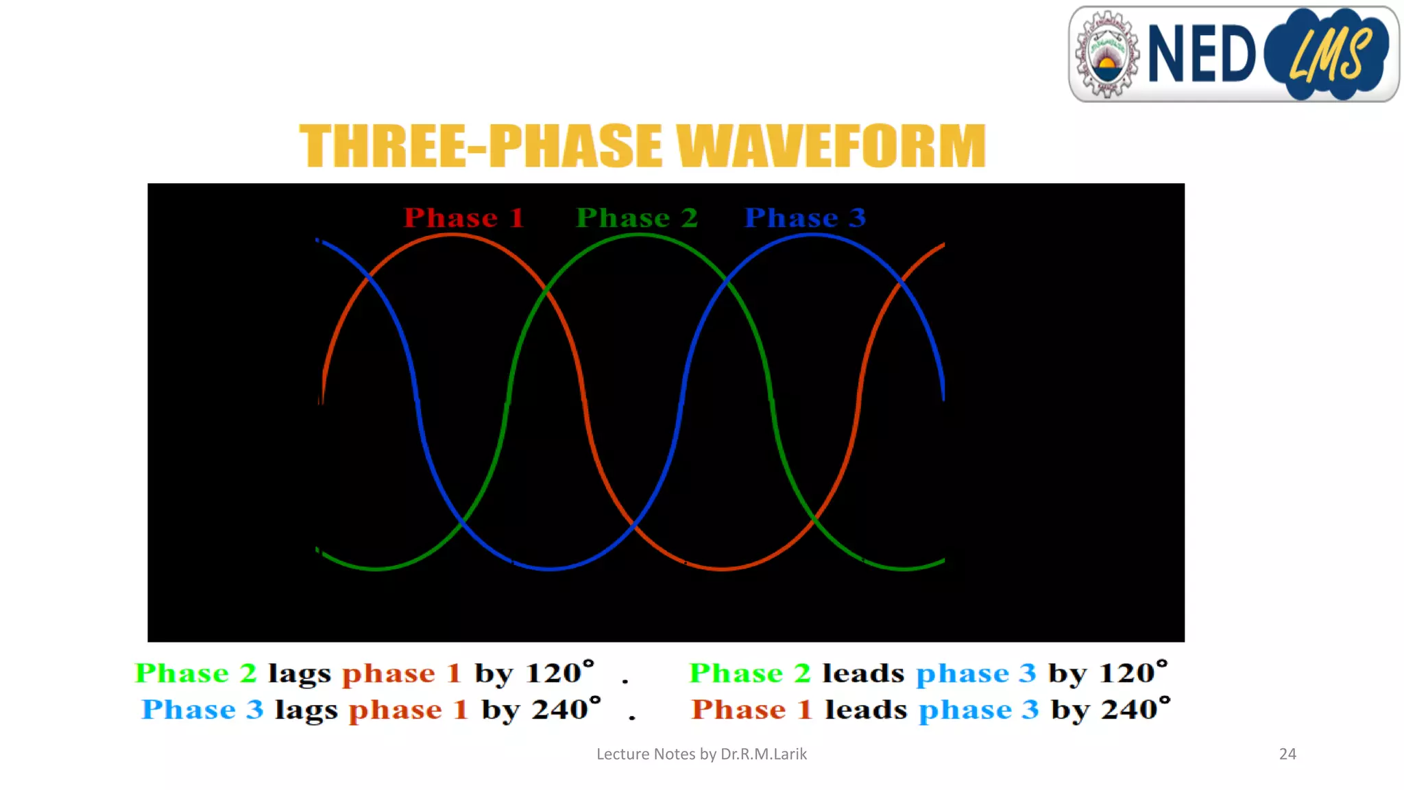
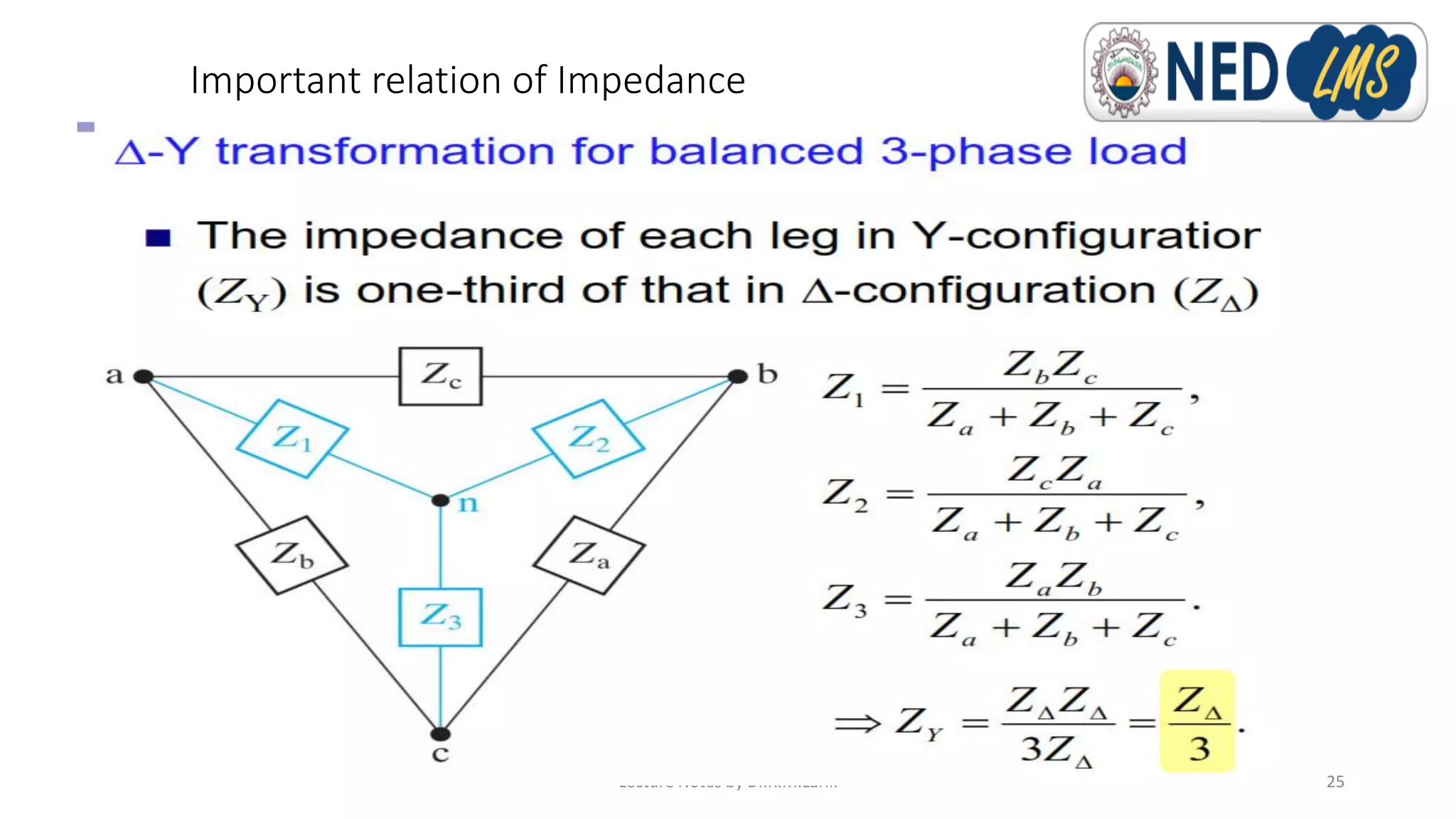
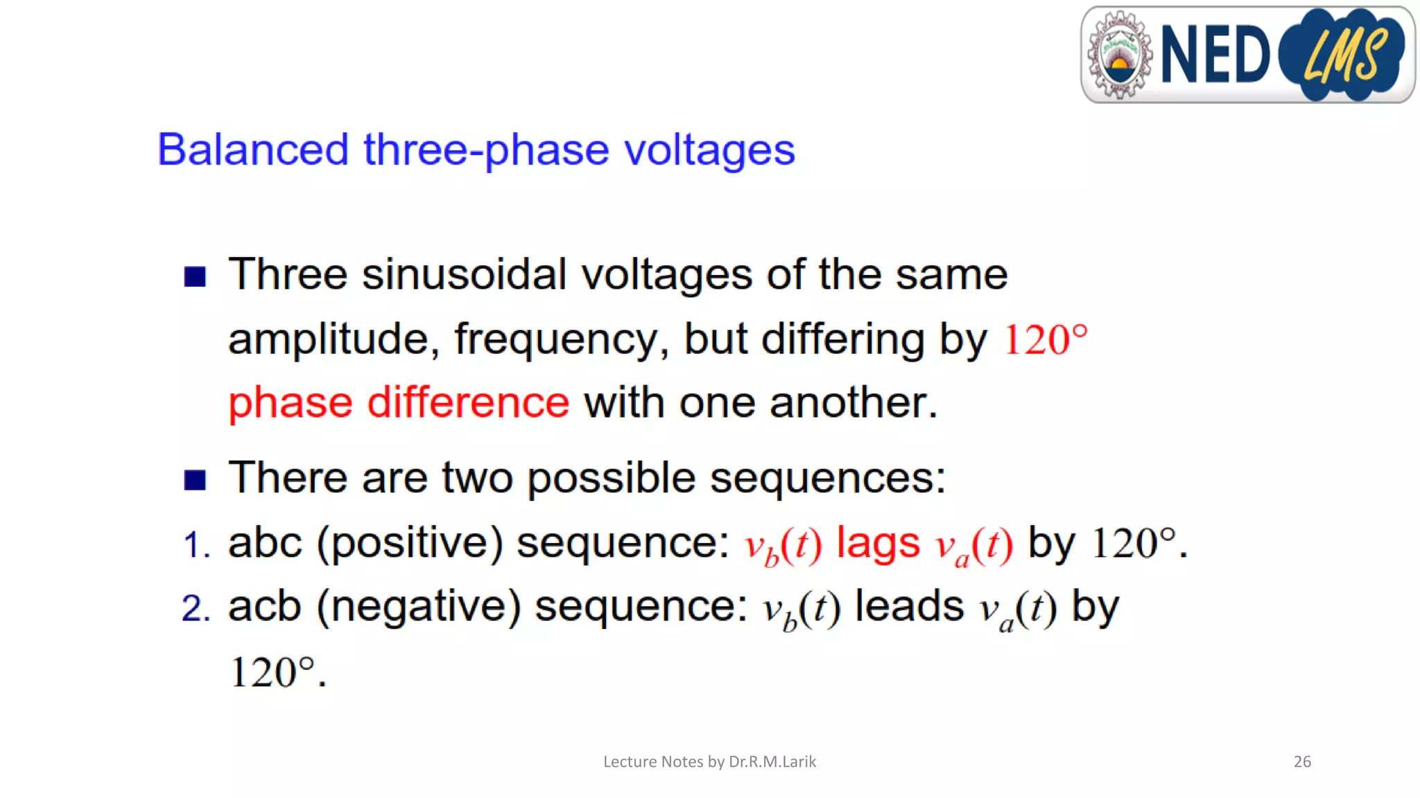
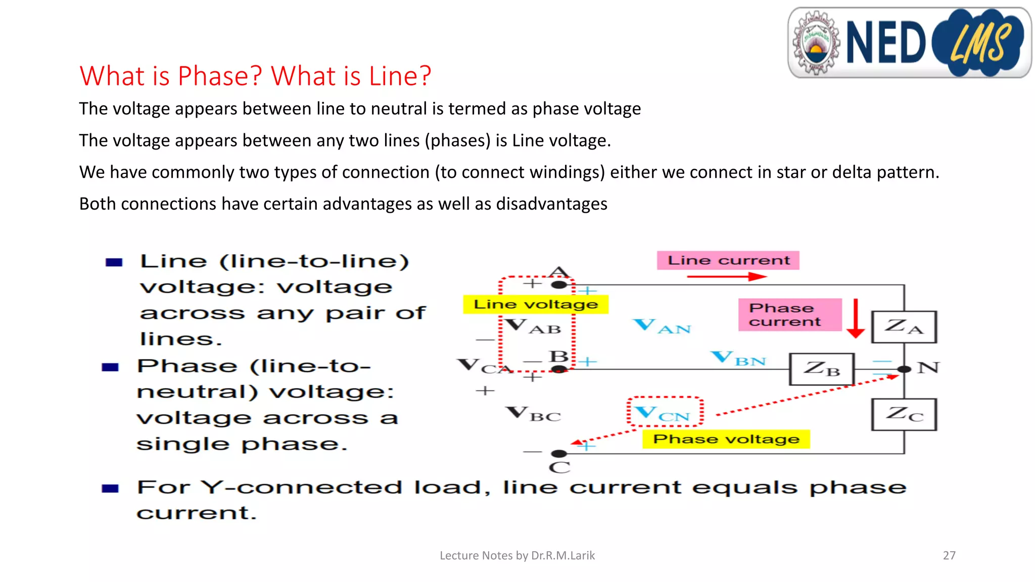
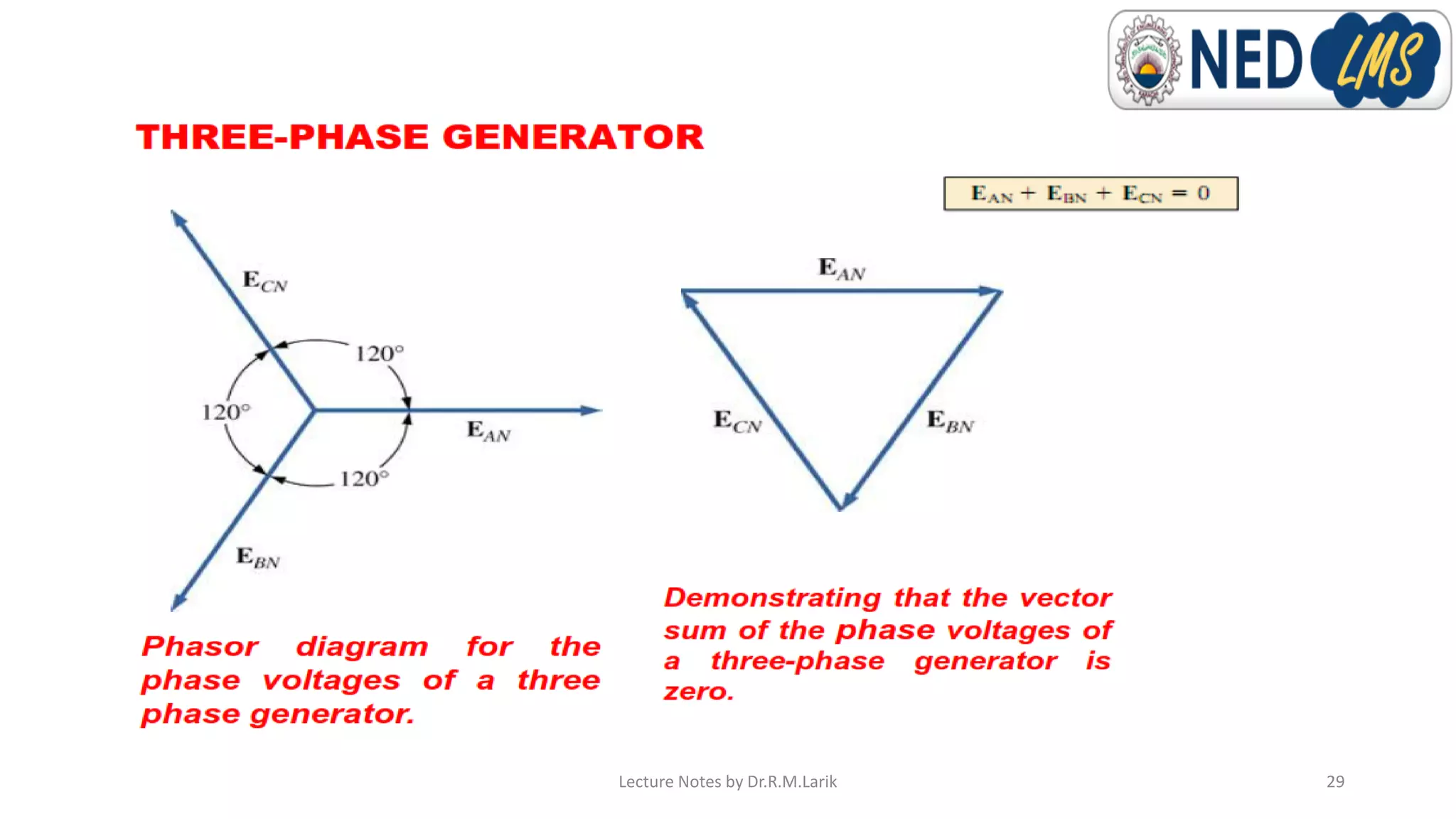
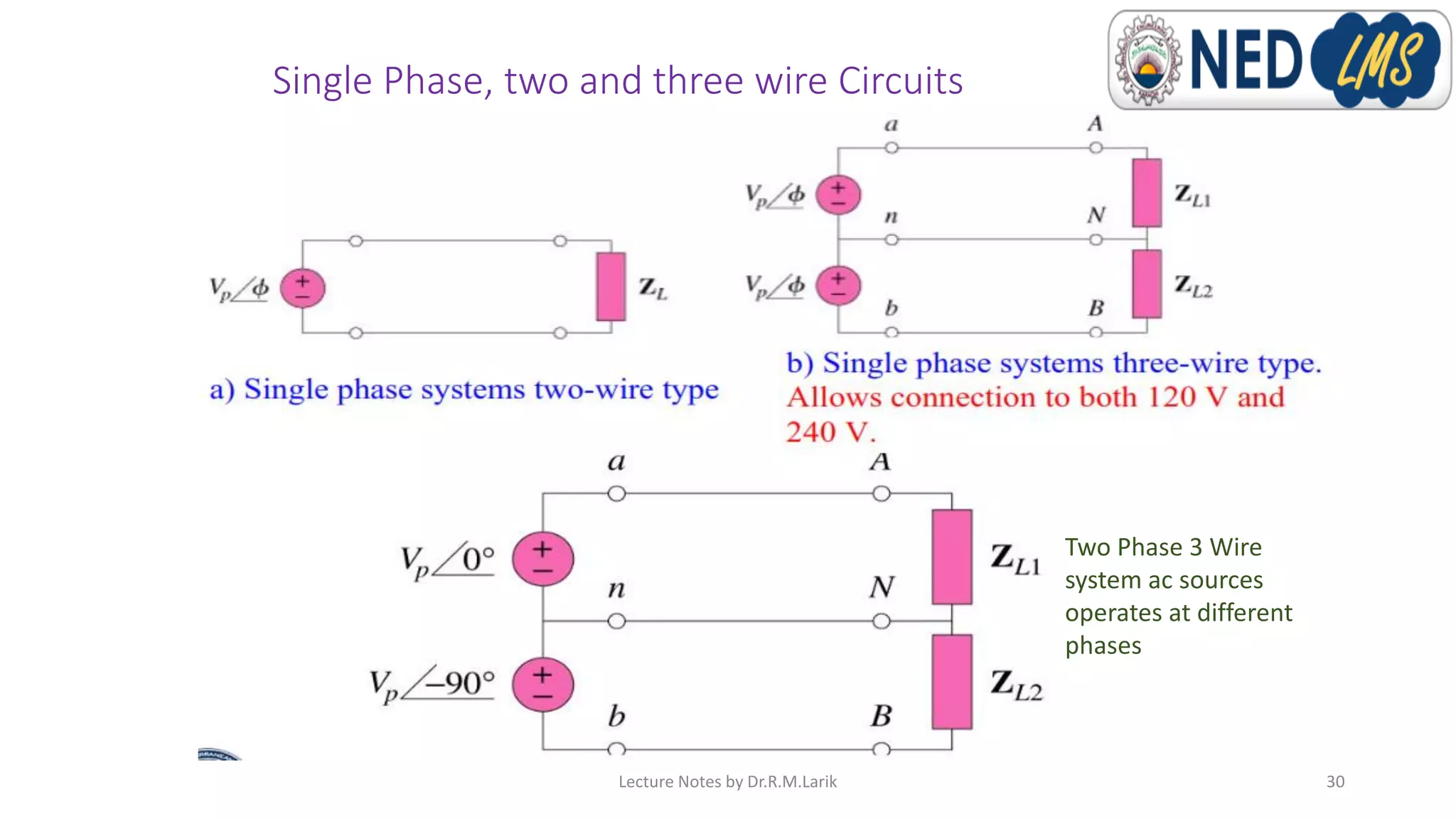
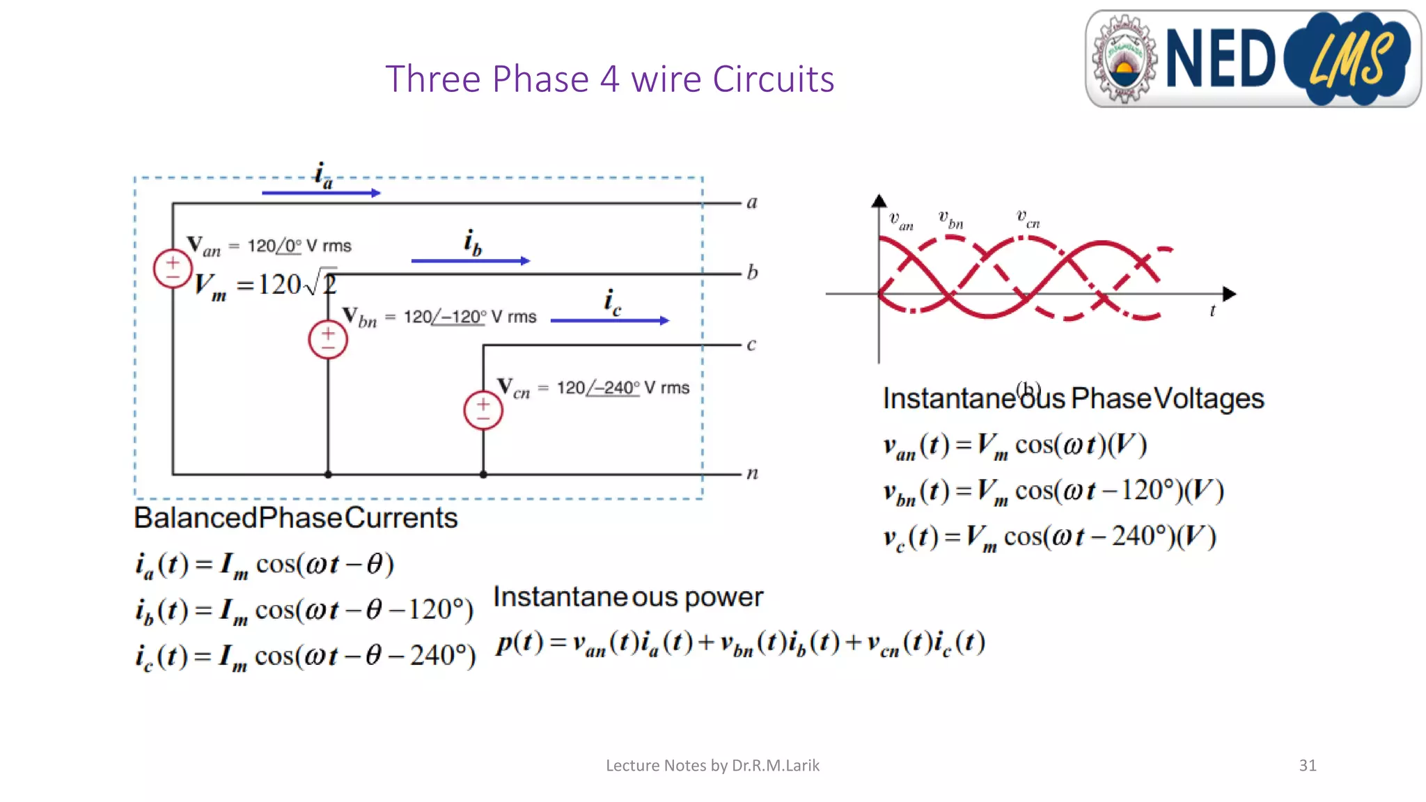
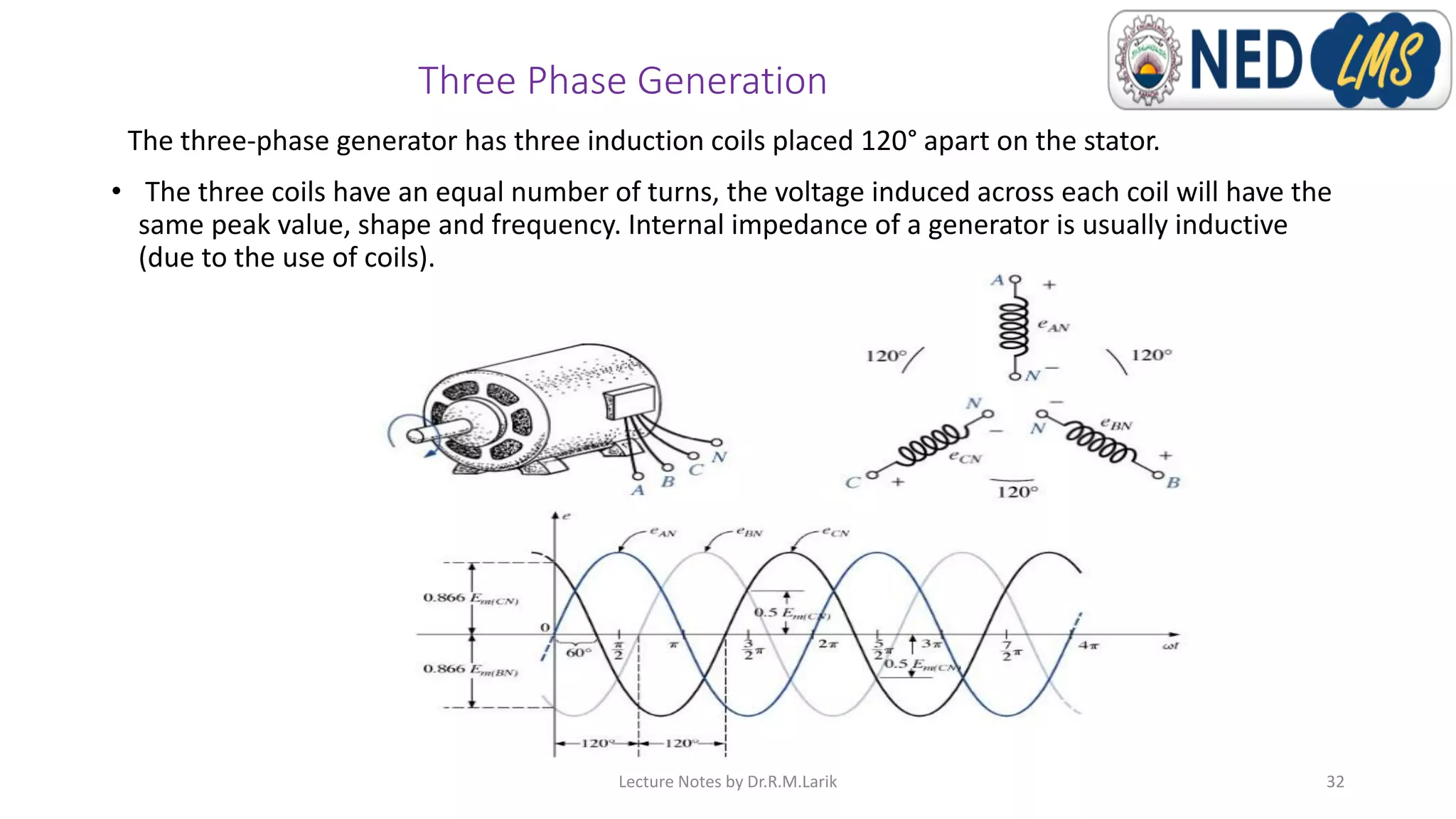
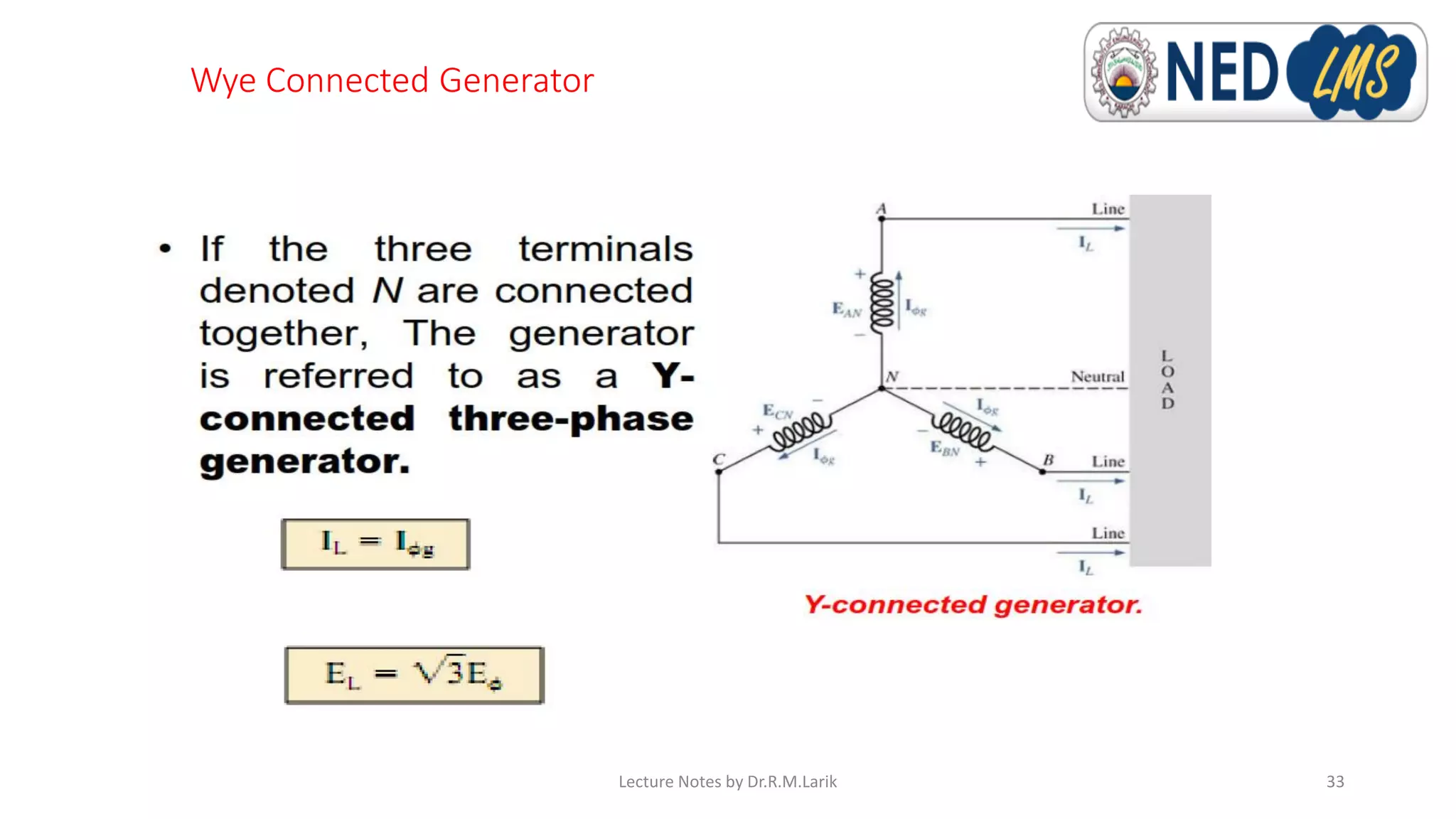
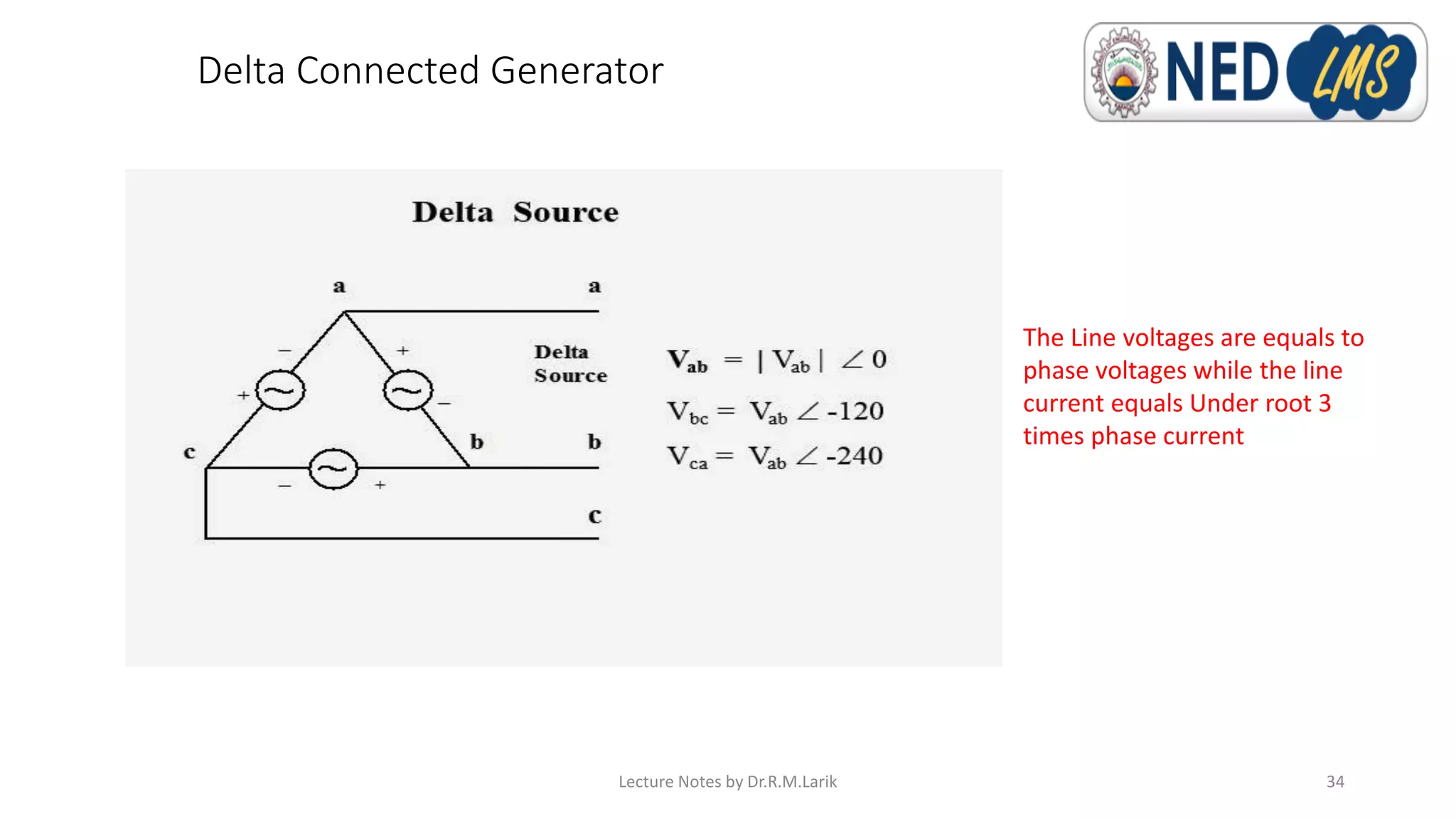
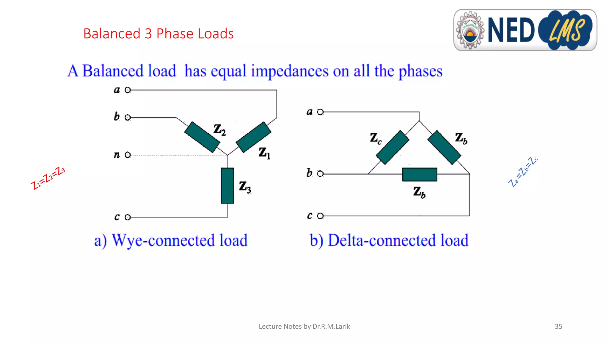
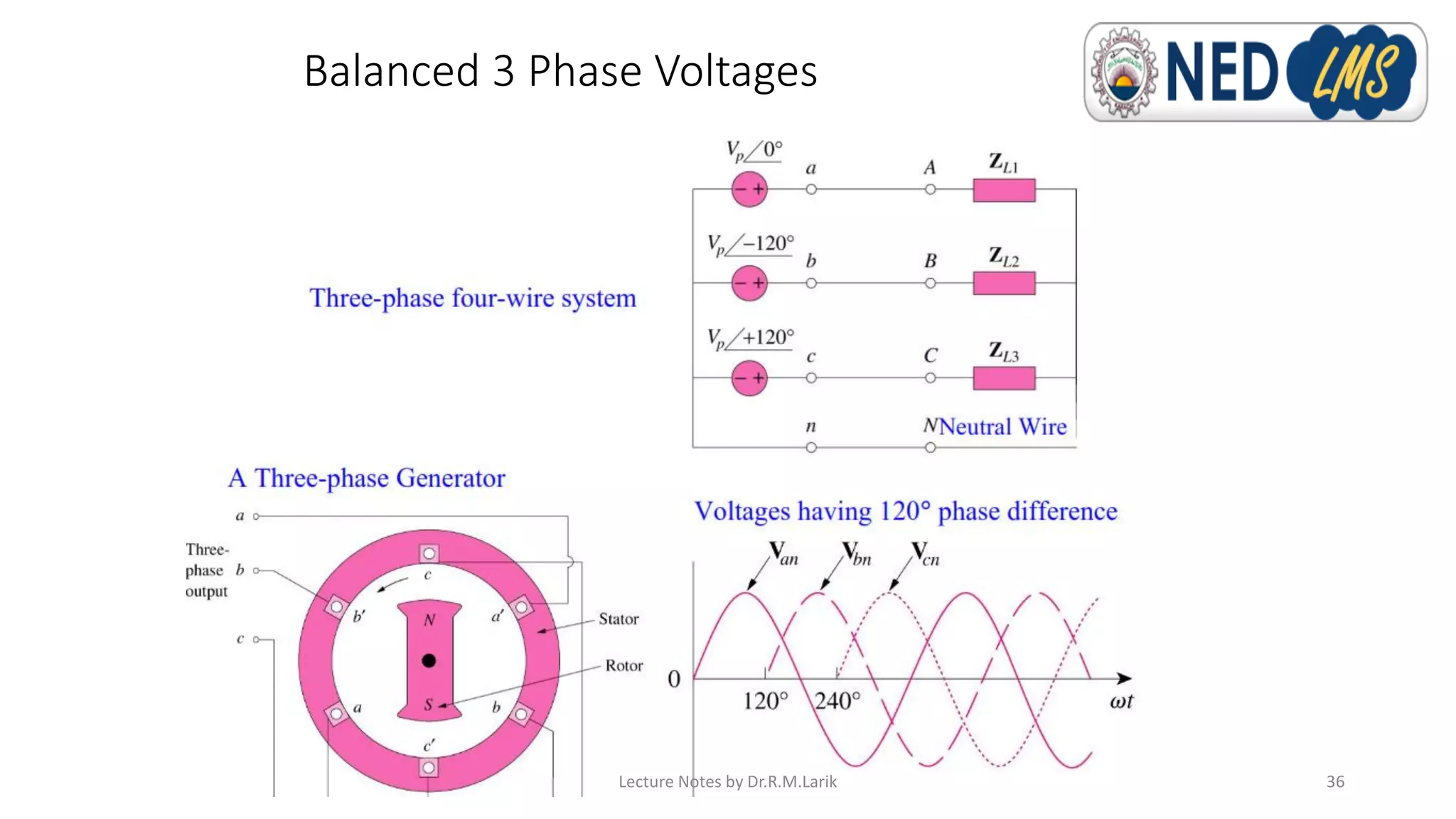
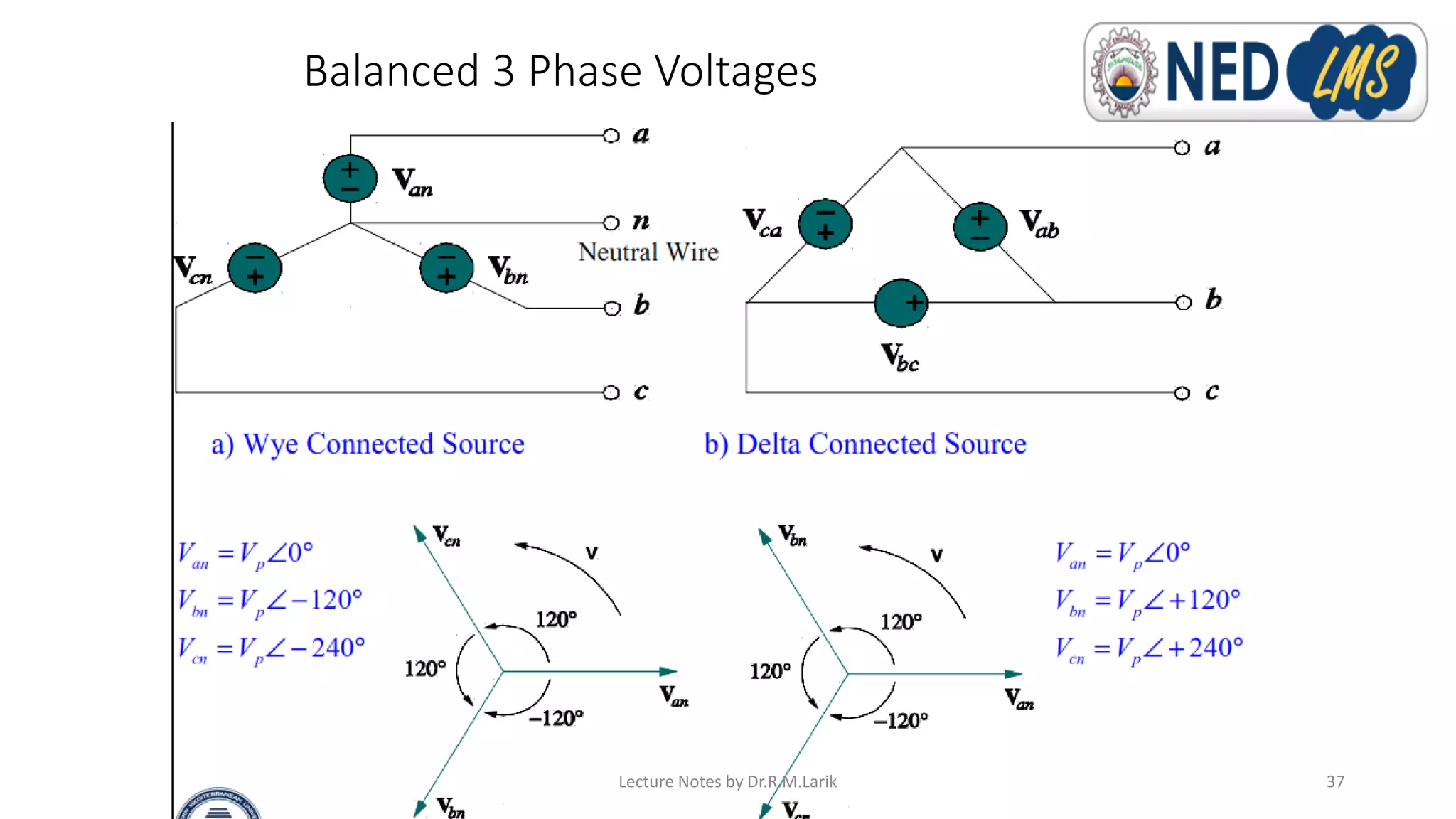
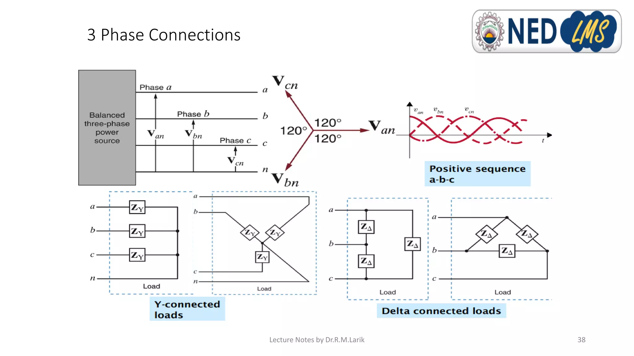
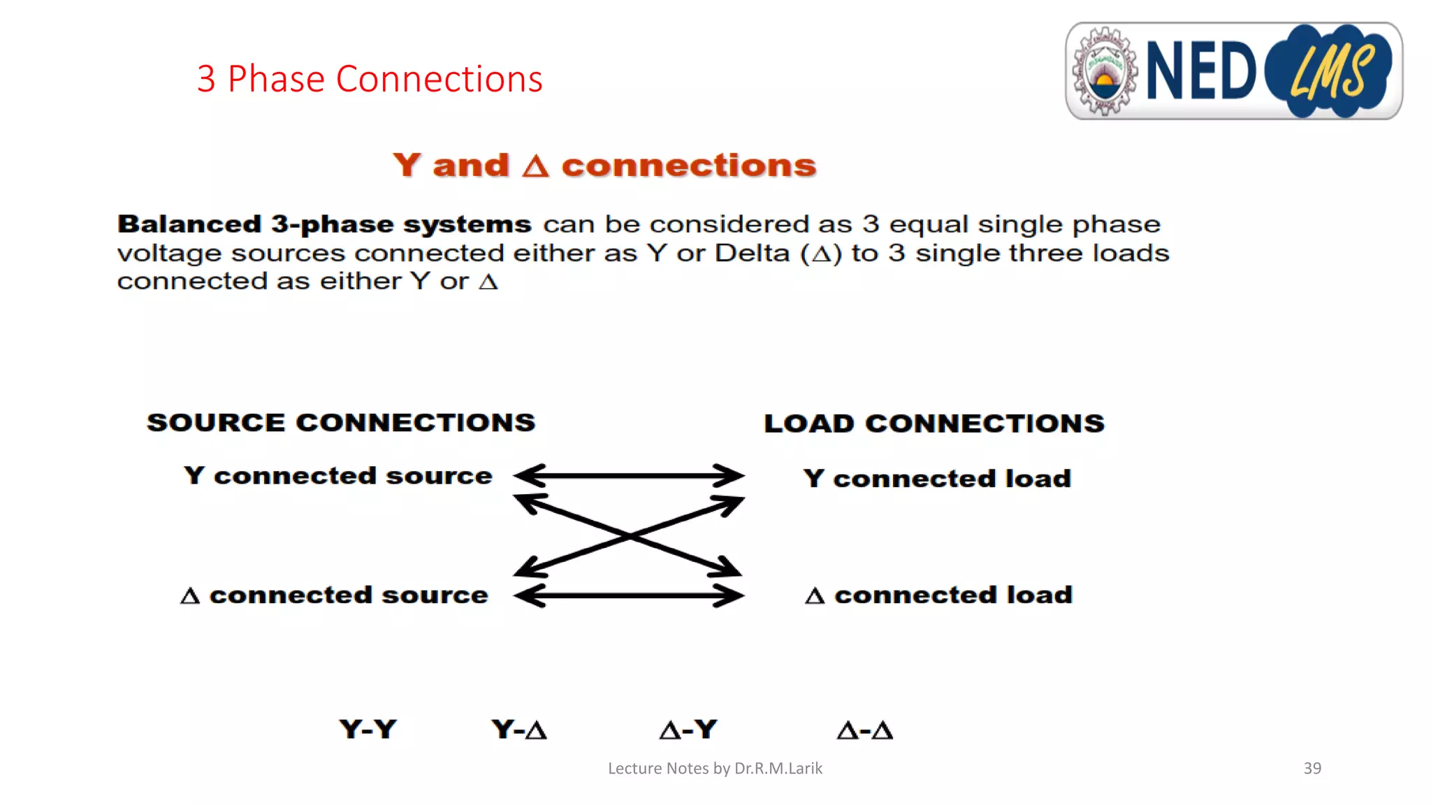
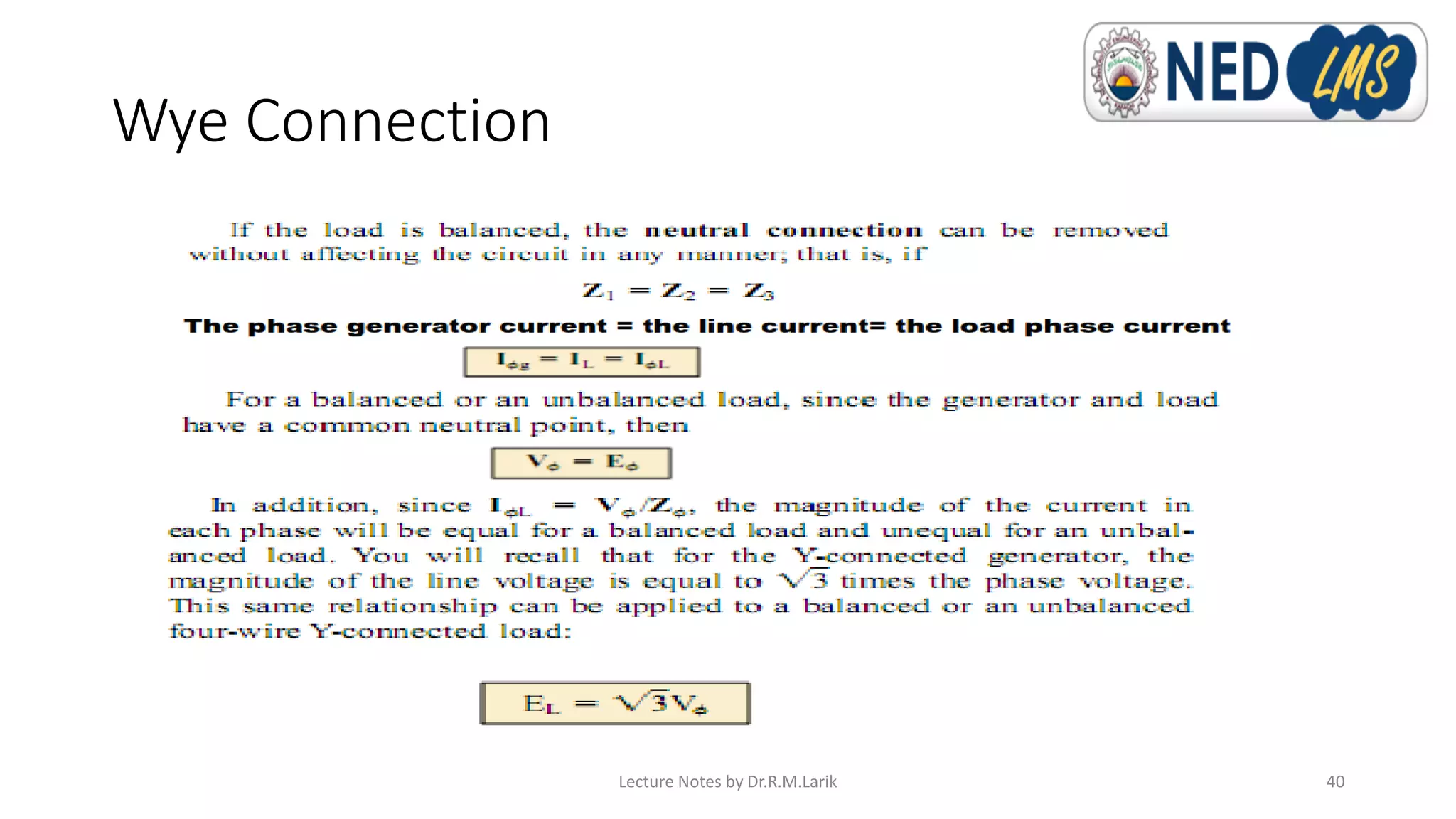
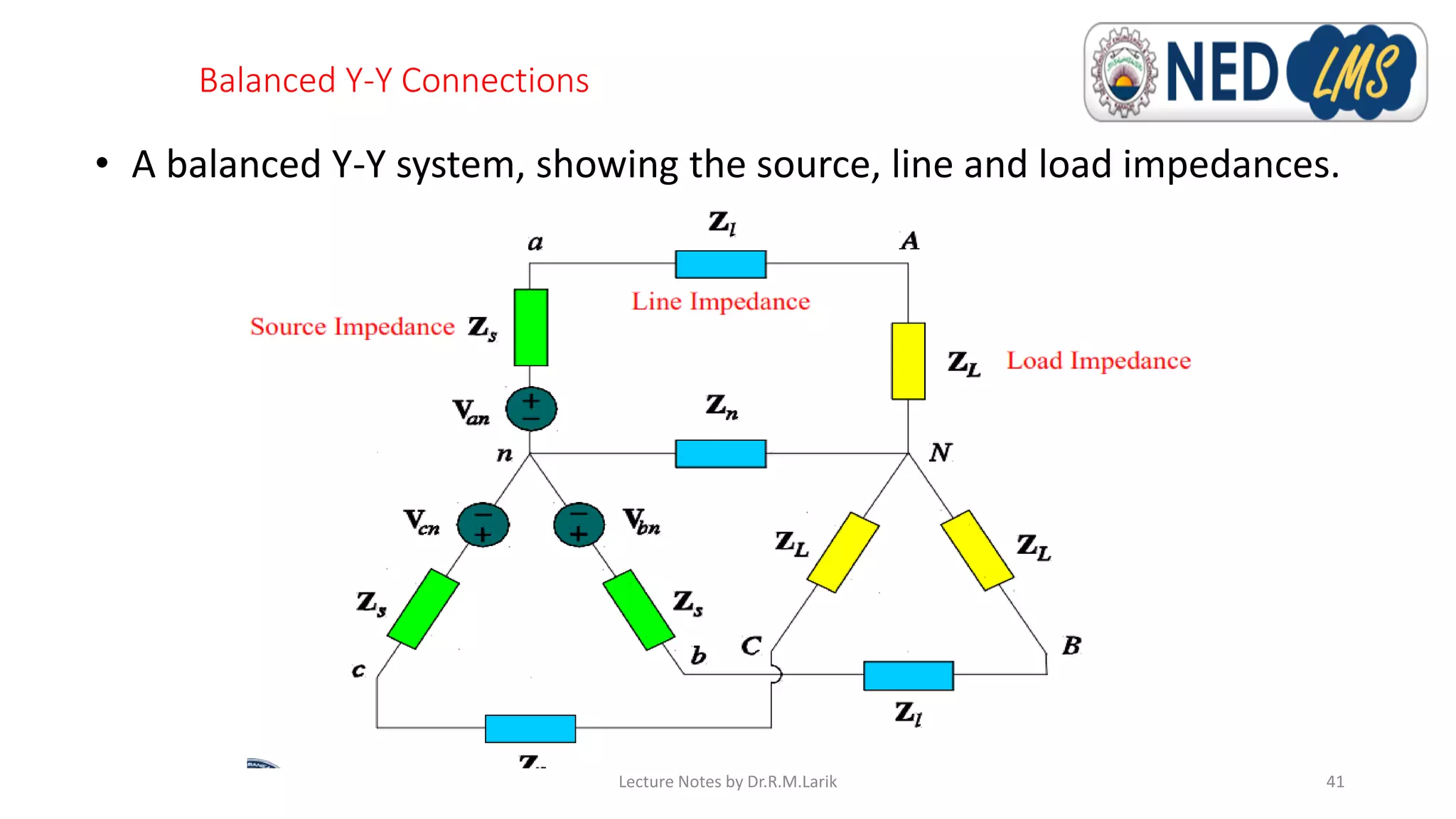
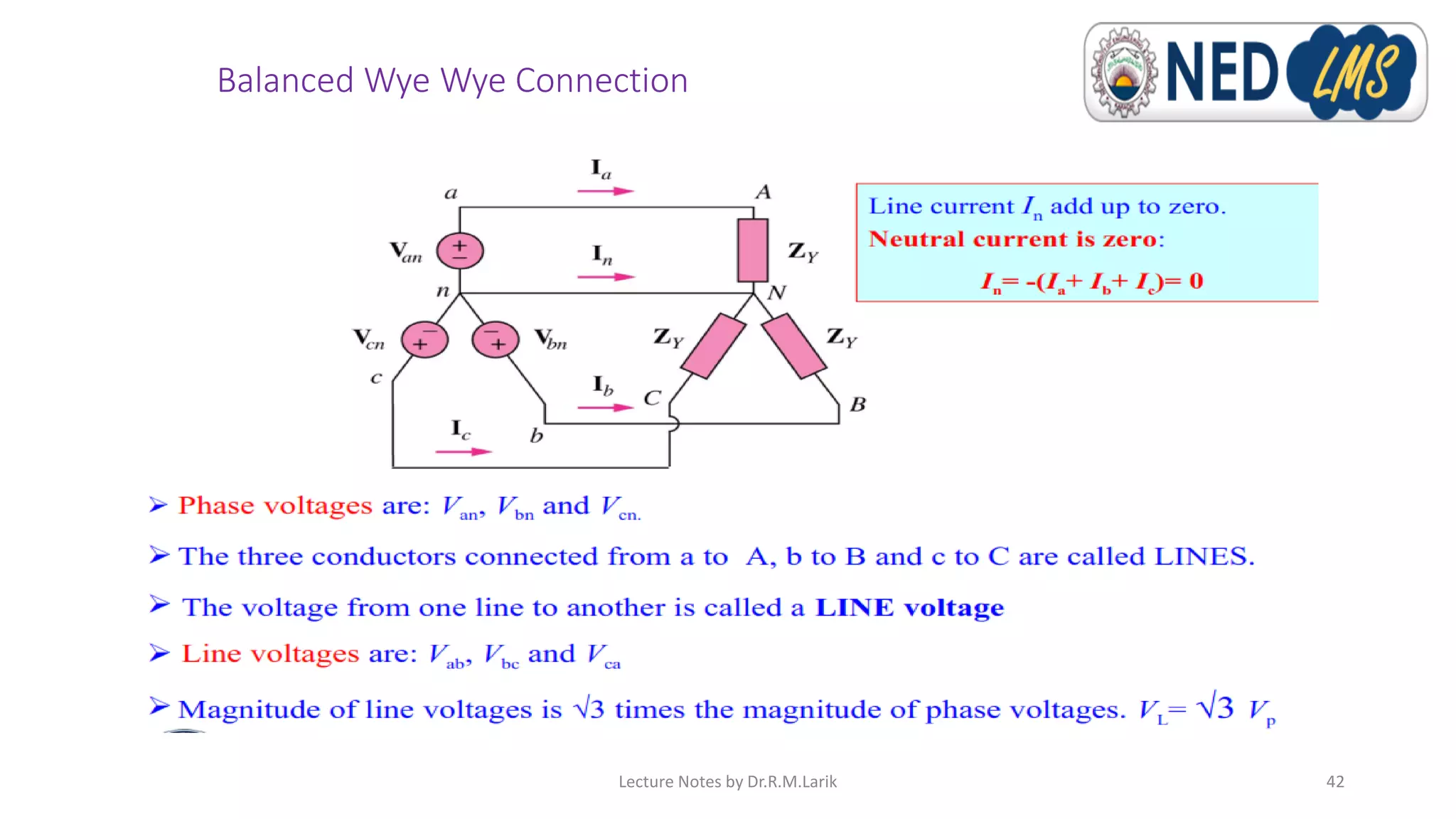
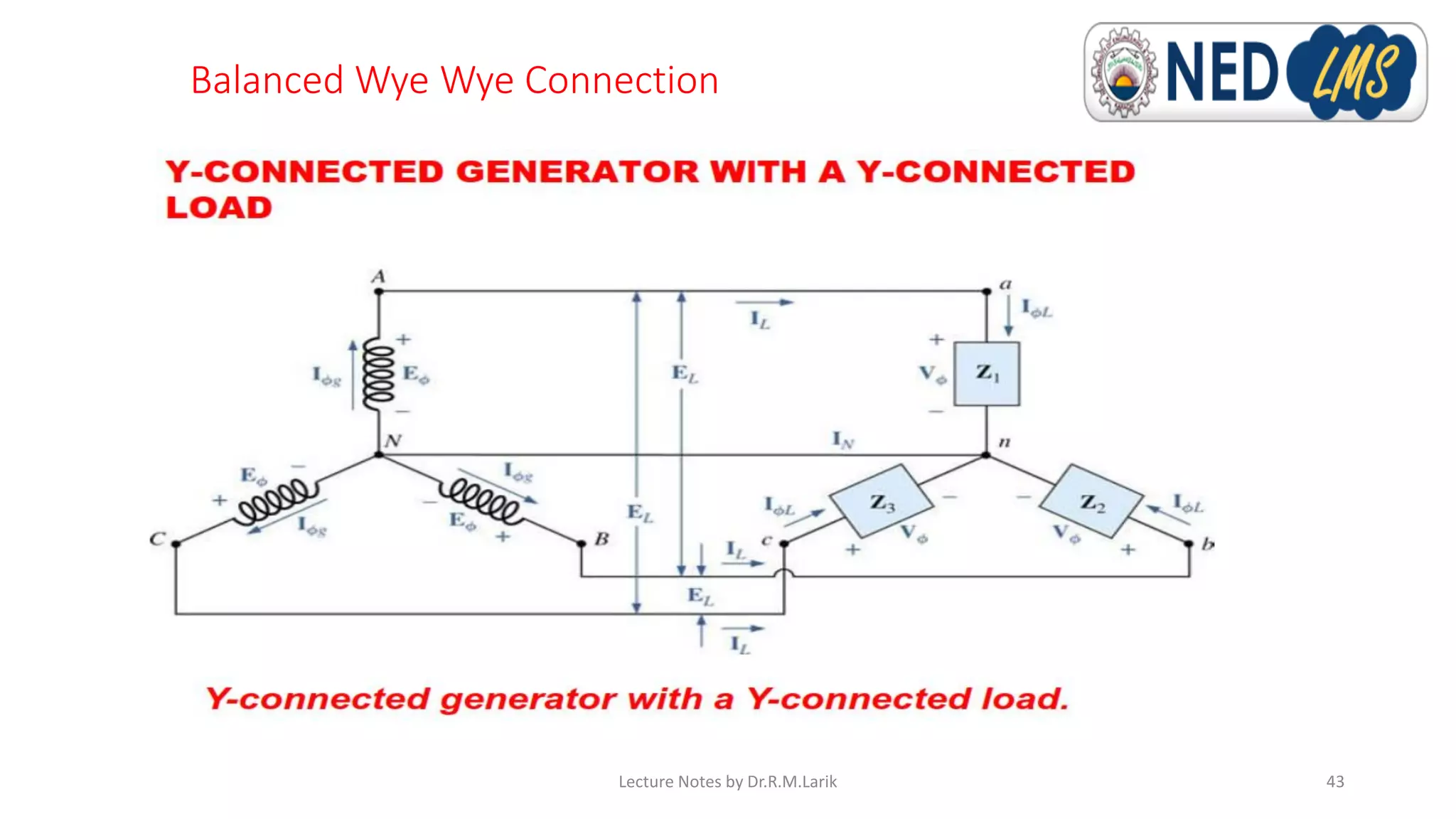
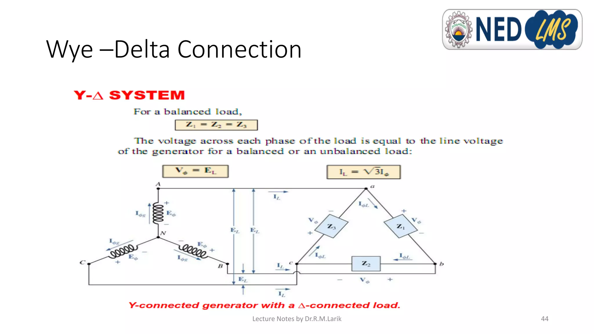
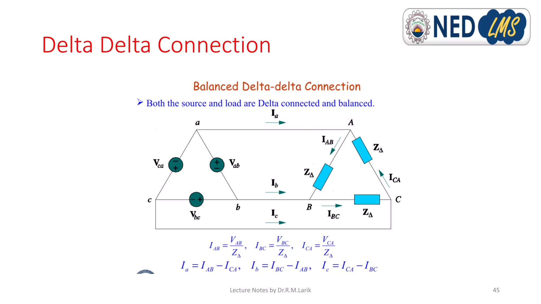
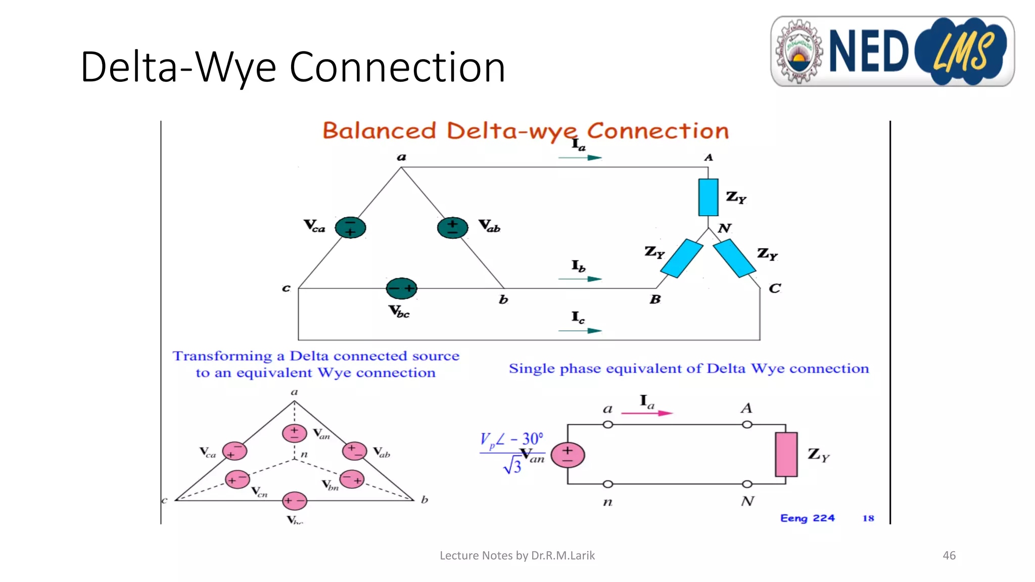

This document contains lecture notes for a Circuit Analysis course taught by Dr. Raja Masood Larik. It includes information about the instructor's educational background and research interests. The notes cover topics like polyphase circuits, three-phase generation and different three-phase connections including wye-wye, delta-delta, wye-delta and delta-wye. Diagrams are provided to illustrate balanced and unbalanced systems as well as how voltage and current values differ between line and phase quantities depending on the type of connection.