Download as PDF, PPTX
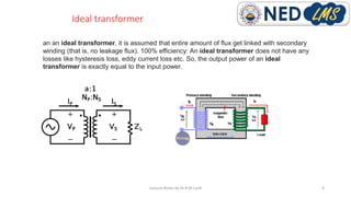
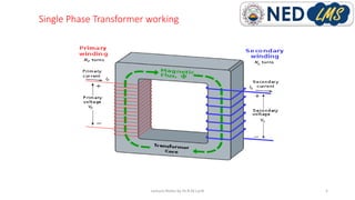
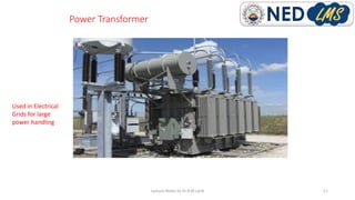
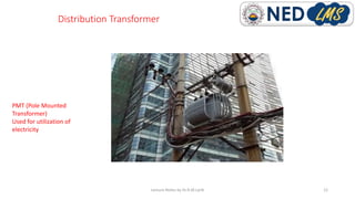
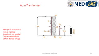

A transformer works on the principle of mutual induction to convert alternating current from one voltage to another. It consists of two coils - a primary coil and secondary coil - wound around an iron core. As current flows through the primary coil, it produces a changing magnetic field that induces a voltage in the secondary coil through electromagnetic induction. This allows electrical energy to be transferred between the coils without a direct connection. Transformers can step voltages up or down and are used widely in power transmission and distribution systems.