220kv sub station kishangarh bas, alwar
•Download as PPTX, PDF•
4 likes•952 views

this is important helpful materiel for engineering students.

Recommended
More Related Content
What's hot
What's hot (20)
Similar to 220kv sub station kishangarh bas, alwar
Similar to 220kv sub station kishangarh bas, alwar (20)
Recently uploaded
Recently uploaded (20)
220kv sub station kishangarh bas, alwar
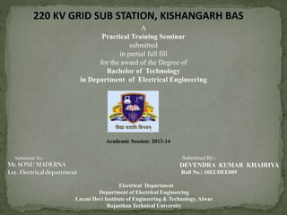
- 1. A Practical Training Seminar submitted in partial full fill for the award of the Degree of Bachelor of Technology in Department of Electrical Engineering Submitted To:- Submitted By:- DEVENDRA KUMAR KHAIRIYA Roll No.: 10ELDEE009 Electrical Department Department of Electrical Engineering Laxmi Devi Institute of Engineering & Technology, Alwar Rajasthan Technical University Academic Session: 2013-14 220 KV GRID SUB STATION, KISHANGARH BAS
- 2. CONTENTS OF PRESENTATION: •Introduction • Bird view of Sub-station • 220-KV Sub-station of kishangarh bas • Definition Of Sub-station •Parts of 220kv gss of kishangarh bas •Functions of substation equipments
- 3. This project includes study of yard, administration block, bus bars, circuit breakers, relays, isolators, various types of transformers such as power transformers, capacitor voltage transformer, current transformer, lighting arresters and grounding system of sub-station.
- 4. BIRD VIWE OF SUBSTATION
- 5. INCOMING FEEDERS AT 220KV GSS K G BAS • KHUSHKHERA • ALWAR OUTGOING FEEDER AT 220 KV GSS K.G. BAS • TIJARA (132 KV) • MUNDAWAR (132 KV) • PUR-KOTKASIM (132 KV) • KHAIRTHAL (33 KV) • K G BAS (33 KV) • HARSOLI (33 KV) • CHIKANI (33 KV) 220 KV SUBSTATION OFKISHANGARH BAS: THERE ARE TWO INCOMING OF 220KV , AND SEVEN OUTGOING OF 132KVAND 33KV
- 6. Sub-station is a subsidiary station of an electricity generation, transmission and distribution system where voltage is transformed from high to low or low to high voltage using transformers and other helping equipments. It consist yard and administration block.
- 7. THERE ARE TWO PART OF THE 220 KV K G BAS GSS: 1. YARD:- In K.G. Bas the yard contains two transformer of 100MVA, which step down voltage from 220 kv to 132 kv. There are four bus-bars in 220 kv yard .Yard also contain air blast circuit breakers, isolators, insulator, current transformer ,potential transformer, lightning arrestor’s etc. Some auxiliary equipment like compressor, oil filters, wave trap for plcc are also provided in the yard YARD
- 9. LIGHTNING ARRESTER CURRENT TRANSFORMER ISOLATOR CIRCUIT BREAKER POWER TRANSFORMER CAPACITOR VOLTAGE TRANSFORMER CAPACITOR BANK INSULATOR BUS BAR SYSTEM WAVE TRAPE
- 10. A LIGTNING ARRESTER IS A PROTECTIVE DEVICE WHICH CONDUCT THE HIGH VOLTAGE SURGE ON THE POWER SYSTEM TO THE GROUND.
- 11. Current transformer is a instrument transformer which is mainly used for measuring current where very high currents are flowing. ACTUAL VIEW
- 13. A circuit breaker is an equipment which can open or close a circuit under normal as well as fault condition. MAINLY CIRCUIT BREAKER USED ARE ABCB(AIR BLAST CIRCUIT BREAKER) SF6(SULPHUR HEXA FLOURIDE) CIRCUIT BREAKER SF6 GAS CIRCUIT BREAKER
- 14. POWER TRANSFORMER A transformer is a static electrical device that transfers energy by inductive coupling between its winding circuits. A varying current in the primary winding creates a varying magnetic flux in the transformer's core and thus a varying magnetic flux through the secondary winding. This varying magnetic flux induces a varying electromotive force (emf) or voltage in the secondary winding. IDEAL TRANSFORMER CIRCUIT DIAGRAM
- 15. Consider the ideal, lossless, perfectly-coupled transformer shown in the circuit diagram at right having primary and secondary windings with NP and NS turns, respectively. The ideal transformer induces secondary voltage ES =VS as a proportion of the primary voltage VP = EP and respective winding turns as given by the equation, , where, -VP/VS = EP/ES = a is the voltage ratio and NP/NS = a is the winding turns ratio, -the value of these ratios being respectively higher and lower than unity for step- down and step-up transformers, -- VP designates source impressed voltage, -VS designates output voltage, and, - - EP & ES designate respective emf induced voltages.
- 16. , Any load impedebce ZL connected to the ideal transformer's secondary winding causes current to flow without losses from primary to secondary circuits, the resulting input and output apparent power therefore being equal as given by the equation The load impedance ZL is defined in terms of secondary circuit voltage and current as follows The apparent impedance z’L of this secondary circuit load referred to the primary winding circuit is governed by a squared turns ratio multiplication factor relationship derived as follows
- 17. IDEAL TRANSFORMER CIRCUIT DIAGRAM
- 19. MAIN TANK CONSERVATOR TANK RADIATORS RADIATOR FANS SILICA GEL BREATHERS BUCHHOLZ RELAY
- 20. conservator tank is also used for OLTC (on load tap changer). OLTC also needs oil for its smooth working and for cooling purpose as for transformer . conservator actually works for oltc CONSERVATOR TANK FIGURE
- 21. Radiators are heat exchanger used to transfer thermal energy from one medium to another for the purpose of cooling and heating. RADIATOR FIGURE
- 22. Silica Gel Breather is used to dehydrate the air and remove dust particles of the air breathed in by the transformer and make sure that the air entering into the transformer is free from moisture and dust particles SILICA GEL BREATHER FIGURE
- 23. In the field of electric power distribution and transmission, a Buchholz relay is a safety device mounted on some oil-filled power transformers and reactors, equipped with an external overhead oil reservoir called a conservator. The Buchholz Relay is used as a protective device sensitive to the effects of dielectric failure inside the equipment BUCHHOLZ RELAY FIGURE
- 24. Radiator fans are used for cooling internal combustion engines.
- 25. CAPACITIVE VOLTAGE TRANSFORMER(C.V.T.) A capacitive voltage transformer (CVT), or capacitive coupled voltage transformer (CCVT) is a transformer used in power systems to step down extra high voltage signals and provide a low voltage signal, for measurement or to operate a protective relay capacitive voltage transformer
- 26. An electrical insulator is a material whose internal electric charges do not flow freely Insulators are used in electrical equipment to support and separate electrical conductors without allowing current through themselves. Main insulators used in gss k.g. bas are: 1.Pin type 2.Suspension type
- 27. CAPACITOR BANK USED FOR POWER FACTOR IMPROVEMENT
- 28. A VIEW OF BUS-BAR ARRENGEMENT IN K G BAS GSS :
- 29. Wave trap is used to communicate between two G.S.S. It traps the frequency of desired level for communication and sends it to P.L.L.C. department WAVE TRAPE FIGURE
- 30. DC is require in sub station for the operation of various protection and control system, such as for the operation of relays. The DC voltage require is generally obtained by converting ac into dc with the use of rectifier ,but for the continuity of this supply when AC is not available for sometime ,a battery room is installed at the substation. The battery keeps floating, so in case of failure of AC the DC supply is not interrupted. BATTERY ROOM FIGURE