Download to read offline

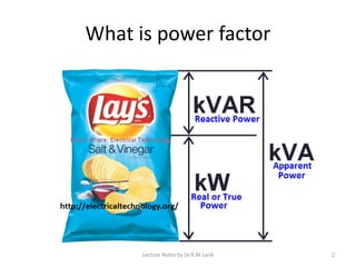
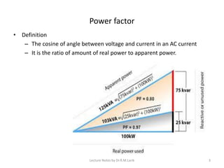
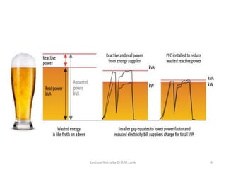
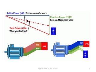
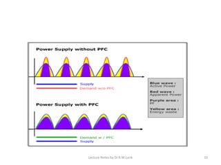
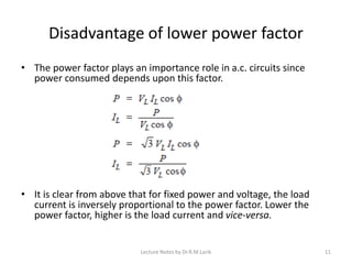
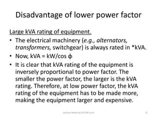


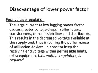


The document discusses power factor and the importance of power factor improvement. It defines power factor as the ratio of active power to apparent power. Power factor is represented by the cosine of the angle between voltage and current. Reactive power causes low power factors by creating an angle between voltage and current. Lower power factors require larger equipment sizes, higher conductor sizes, and cause greater power losses. Common causes of low power factors are induction motors and lighting loads. Power factor improvement provides benefits like reduced costs, equipment sizes, and power losses. The economics of power factor improvement depends on balancing the costs of supply against correction equipment. An example calculation determines the most economical power factor for a factory.