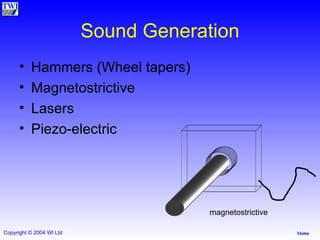
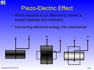
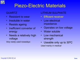
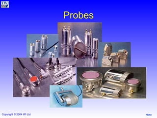
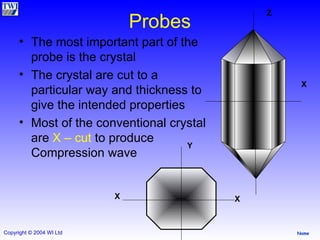
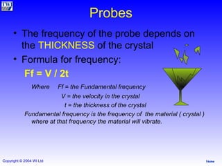
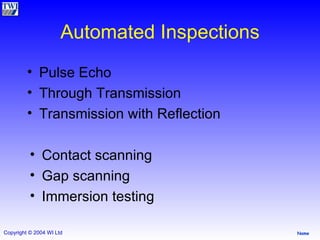
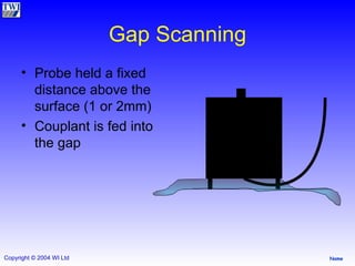
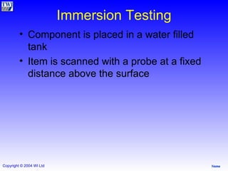
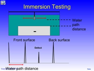
Ultrasonic Testing Part 3 TWI
Sound Generation Hammers (Wheel tapers) Magnetostrictive Lasers Piezo-electric magnetostrictive
Piezo-Electric Effect When exposed to an alternating current a crystal expands and contracts Converting electrical energy into mechanical  -  +  +  -  -  +
Piezo-Electric Materials QUARTZ Resistant to wear Insoluble in water Resists ageing Inefficient converter of energy Needs a relatively high voltage Very rarely used nowadays LITHIUM SULPHATE Efficient receiver Low electrical impedance Operates on low voltage Water soluble Low mechanical strength Useable only up to 30ºC Used mainly in medical
Polarized Crystals Powders heated to high temperatures Pressed into shape Cooled in very strong electrical fields  Examples Barium titanate (Ba Ti O 3 ) Lead metaniobate  (Pb Nb O 6 ) Lead zirconate titanate (Pb Ti O 3  or Pb Zr O 3 ) Most of the probes for conventional usage use   PZT : Lead Zirconate Titanate
Probes
Probes The most important part of the probe is the crystal The crystal are cut to a particular way and thickness to give the intended properties Most of the conventional crystal are  X – cut  to produce Compression wave Z X X X Y
Probes The frequency of the probe depends on the  THICKNESS  of the crystal Formula for frequency: Ff = V / 2t   Where  Ff = the Fundamental frequency   V = the velocity in the crystal   t = the thickness of the crystal Fundamental frequency is the frequency of  the material ( crystal ) where at that frequency the material will vibrate.
Probes The  Thinner  the crystal the  Higher  the frequency Which of the followings has the Thinnest crystal ? 1 MHz Compression probe 5 MHz Compression probe 10 MHz Shear probe 25 MHz Shear probe 25 MHz Shear Probe
Probe Design Compression Probe Normal probe 0 ° Damping Transducer Electrical connectors Housing
Probe Design Shear Probe Angle probe Damping Transducer Perspex wedge Backing medium Probe Shoe
Probe Design Twin Crystal Advantages Can be focused Measure thin plate Near surface resolution Disadvantages Difficult to use on curved surfaces Sizing small defects Signal amplitude / focal spot length Transmitter Receiver Focusing lens Separator / Insulator
Sound Intensity Comparing the intensity of 2 signals Electrical power proportional to the square of the voltage produced Hence
Sound Intensity Will lead to large ratios Therefore
2 signals at 20% and 40% FSH. What is the difference between them in dB’s?
2 signals at 10% and 100% FSH. What is the difference between them in dB’s?
Amplitude ratios in decibels 2 : 1 = 6bB 4 : 1 = 12dB 5 : 1 = 14dB 10 : 1 = 20dB 100 : 1 = 40dB
Automated Inspections Pulse Echo Through Transmission Transmission with Reflection Contact scanning Gap scanning Immersion testing
Gap Scanning Probe held a fixed distance above the surface (1 or 2mm) Couplant is fed into the gap
Immersion Testing Component is placed in a water filled tank  Item is scanned with a probe at a fixed distance above the surface
Immersion Testing Water path distance Water path distance Front surface Back surface Defect

Ut P3

  • 1.
  • 2.
    Sound Generation Hammers(Wheel tapers) Magnetostrictive Lasers Piezo-electric magnetostrictive
  • 3.
    Piezo-Electric Effect Whenexposed to an alternating current a crystal expands and contracts Converting electrical energy into mechanical - + + - - +
  • 4.
    Piezo-Electric Materials QUARTZResistant to wear Insoluble in water Resists ageing Inefficient converter of energy Needs a relatively high voltage Very rarely used nowadays LITHIUM SULPHATE Efficient receiver Low electrical impedance Operates on low voltage Water soluble Low mechanical strength Useable only up to 30ºC Used mainly in medical
  • 5.
    Polarized Crystals Powdersheated to high temperatures Pressed into shape Cooled in very strong electrical fields Examples Barium titanate (Ba Ti O 3 ) Lead metaniobate (Pb Nb O 6 ) Lead zirconate titanate (Pb Ti O 3 or Pb Zr O 3 ) Most of the probes for conventional usage use PZT : Lead Zirconate Titanate
  • 6.
  • 7.
    Probes The mostimportant part of the probe is the crystal The crystal are cut to a particular way and thickness to give the intended properties Most of the conventional crystal are X – cut to produce Compression wave Z X X X Y
  • 8.
    Probes The frequencyof the probe depends on the THICKNESS of the crystal Formula for frequency: Ff = V / 2t Where Ff = the Fundamental frequency V = the velocity in the crystal t = the thickness of the crystal Fundamental frequency is the frequency of the material ( crystal ) where at that frequency the material will vibrate.
  • 9.
    Probes The Thinner the crystal the Higher the frequency Which of the followings has the Thinnest crystal ? 1 MHz Compression probe 5 MHz Compression probe 10 MHz Shear probe 25 MHz Shear probe 25 MHz Shear Probe
  • 10.
    Probe Design CompressionProbe Normal probe 0 ° Damping Transducer Electrical connectors Housing
  • 11.
    Probe Design ShearProbe Angle probe Damping Transducer Perspex wedge Backing medium Probe Shoe
  • 12.
    Probe Design TwinCrystal Advantages Can be focused Measure thin plate Near surface resolution Disadvantages Difficult to use on curved surfaces Sizing small defects Signal amplitude / focal spot length Transmitter Receiver Focusing lens Separator / Insulator
  • 13.
    Sound Intensity Comparingthe intensity of 2 signals Electrical power proportional to the square of the voltage produced Hence
  • 14.
    Sound Intensity Willlead to large ratios Therefore
  • 15.
    2 signals at20% and 40% FSH. What is the difference between them in dB’s?
  • 16.
    2 signals at10% and 100% FSH. What is the difference between them in dB’s?
  • 17.
    Amplitude ratios indecibels 2 : 1 = 6bB 4 : 1 = 12dB 5 : 1 = 14dB 10 : 1 = 20dB 100 : 1 = 40dB
  • 18.
    Automated Inspections PulseEcho Through Transmission Transmission with Reflection Contact scanning Gap scanning Immersion testing
  • 19.
    Gap Scanning Probeheld a fixed distance above the surface (1 or 2mm) Couplant is fed into the gap
  • 20.
    Immersion Testing Componentis placed in a water filled tank Item is scanned with a probe at a fixed distance above the surface
  • 21.
    Immersion Testing Waterpath distance Water path distance Front surface Back surface Defect