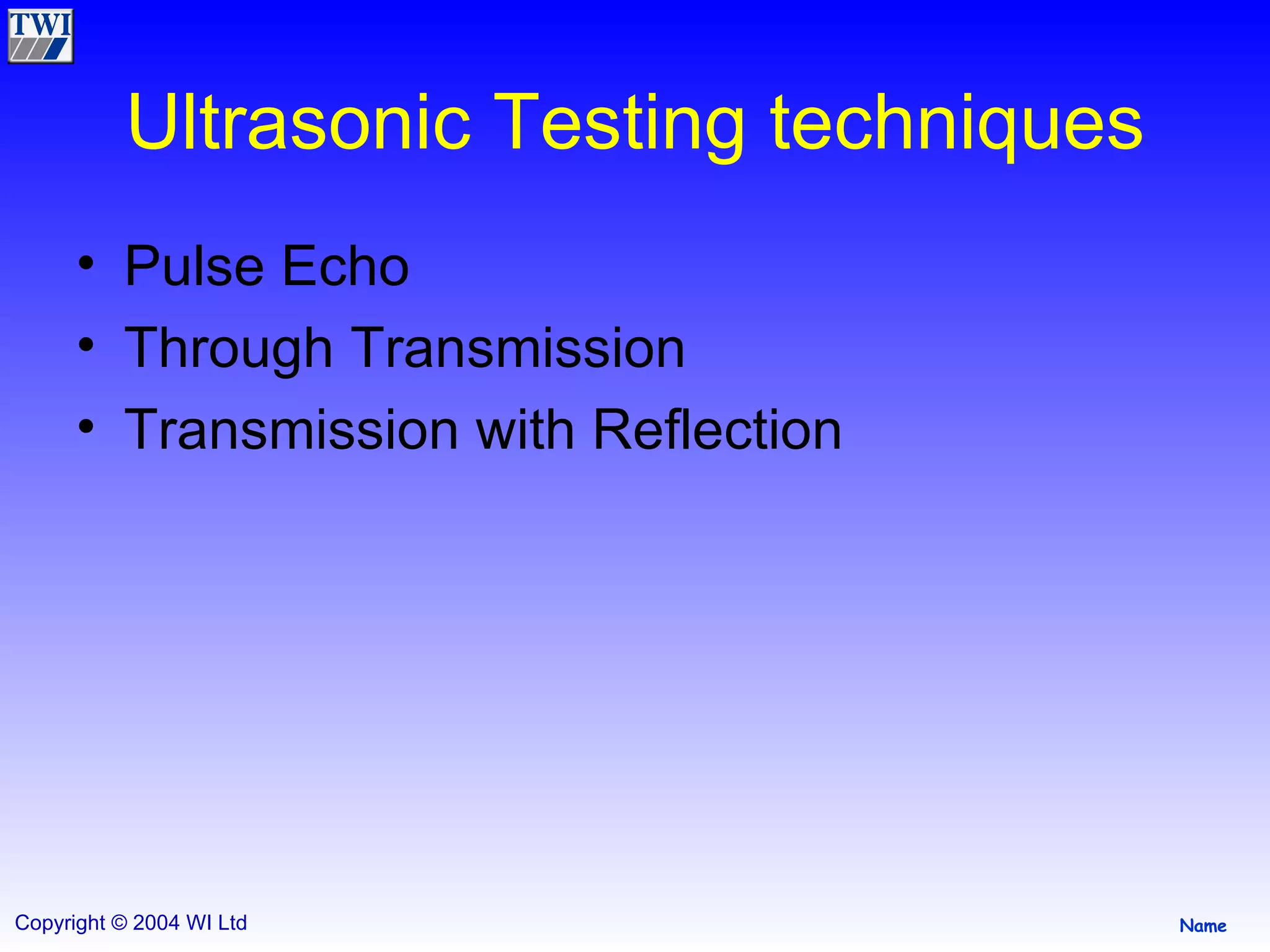
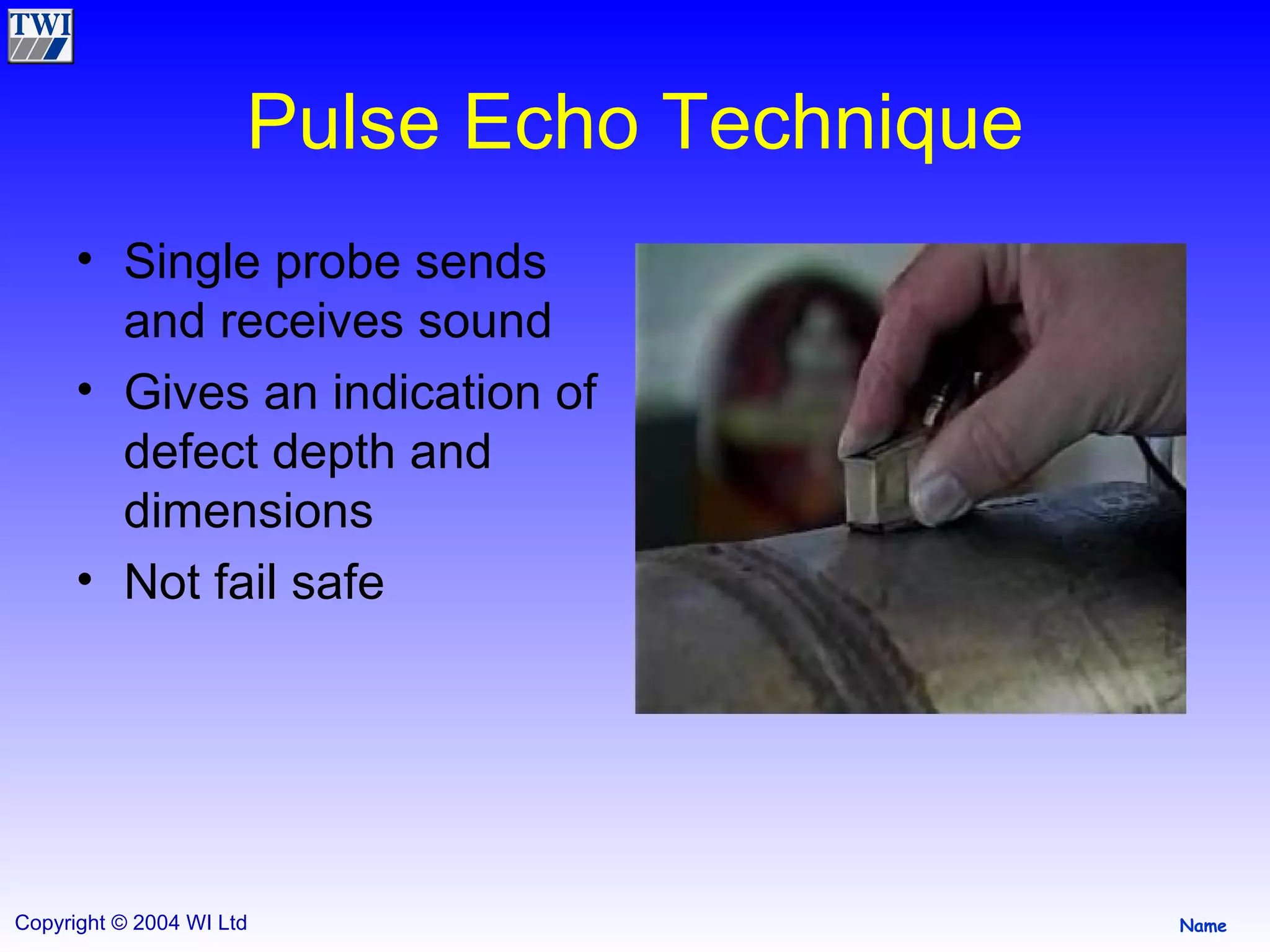
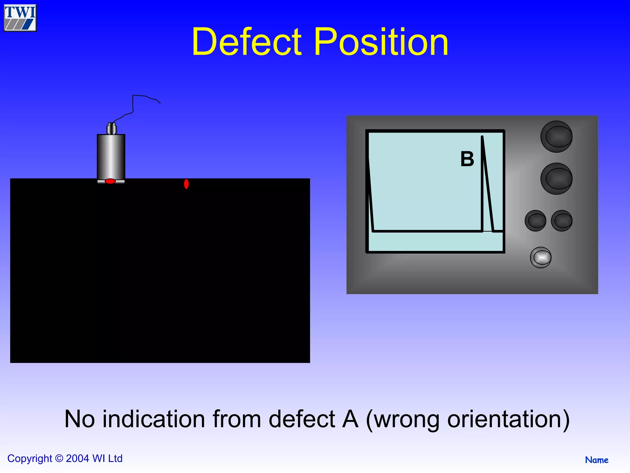
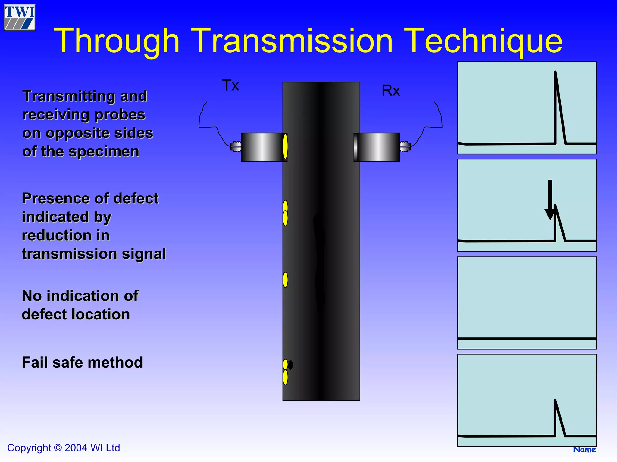
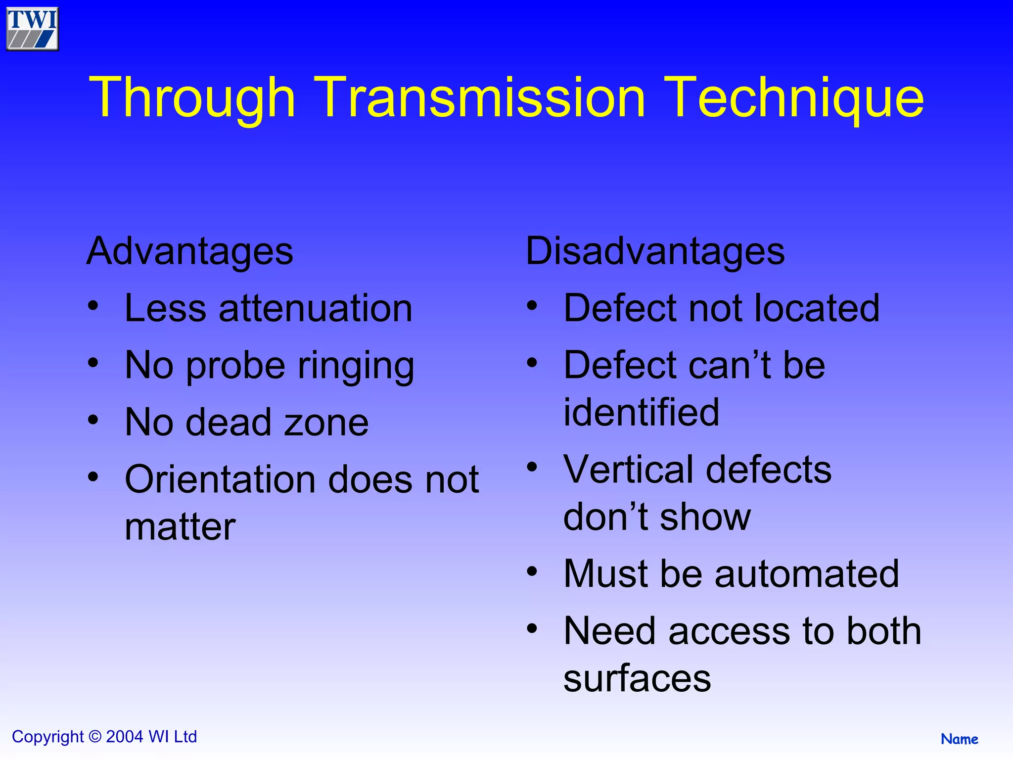
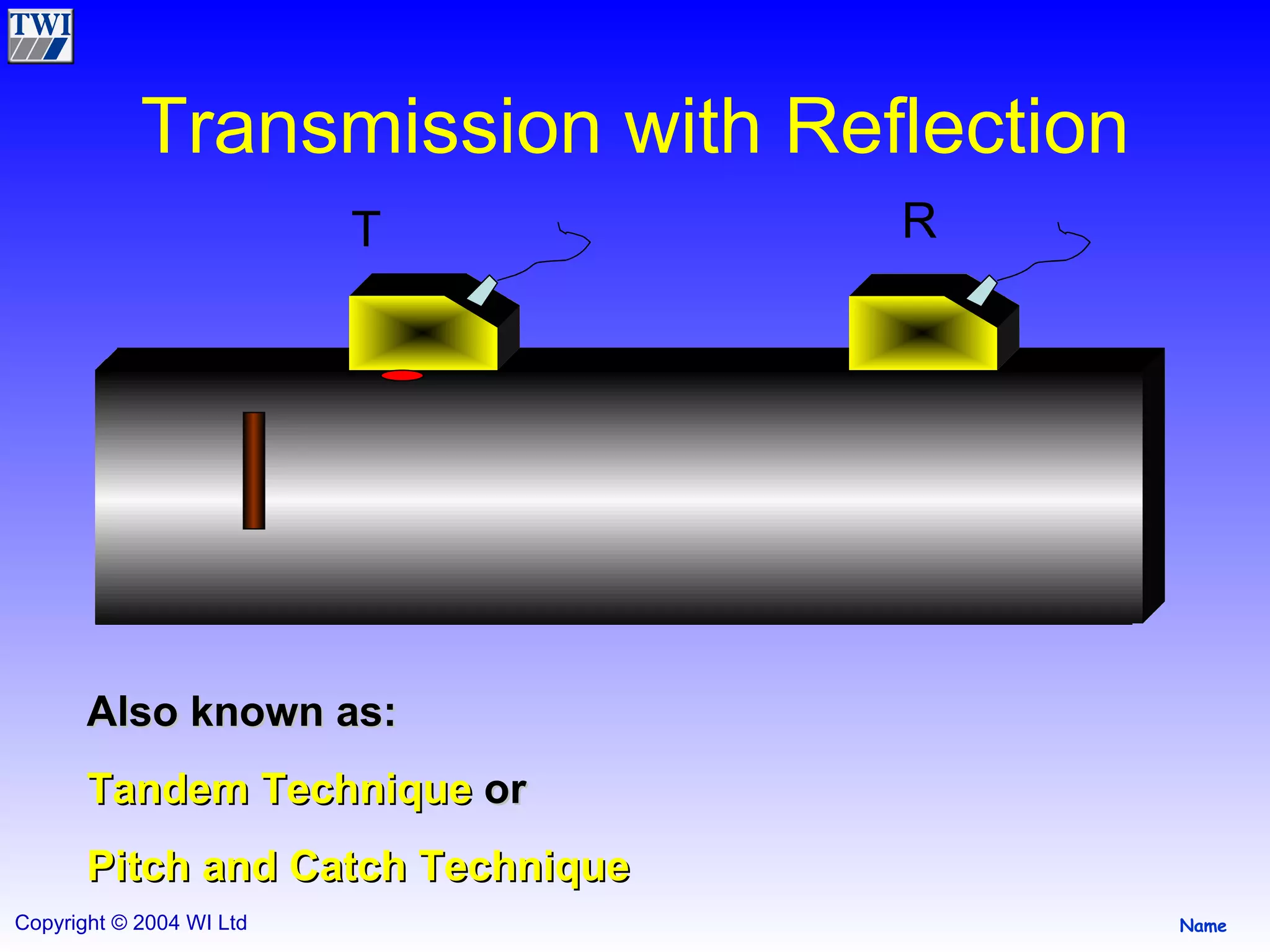
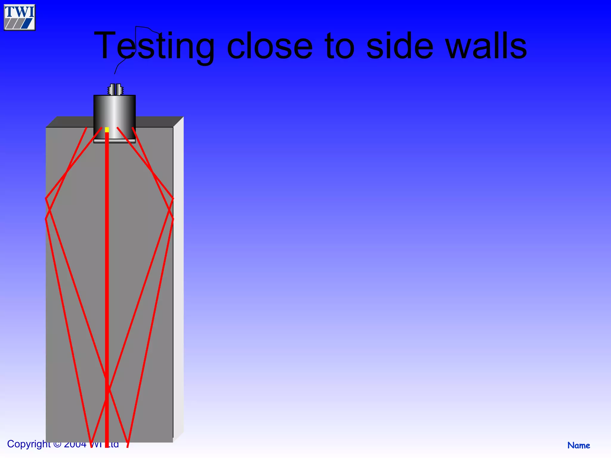
1) Ultrasonic testing techniques include pulse echo, through transmission, and transmission with reflection. Pulse echo uses a single probe to send and receive sound to detect defect depth and orientation. Through transmission uses probes on opposite sides to detect defects but not location. Transmission with reflection can locate defects.
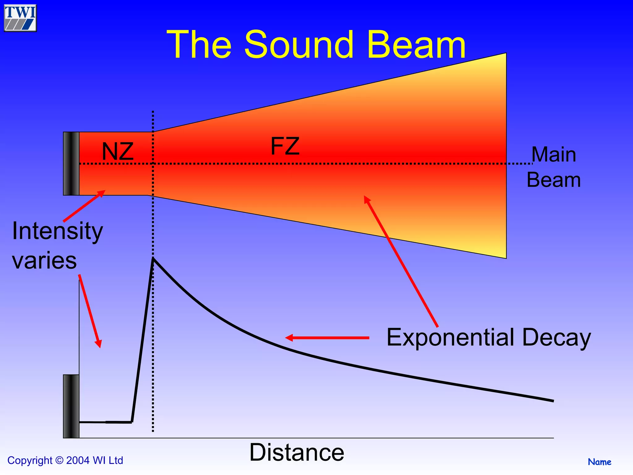
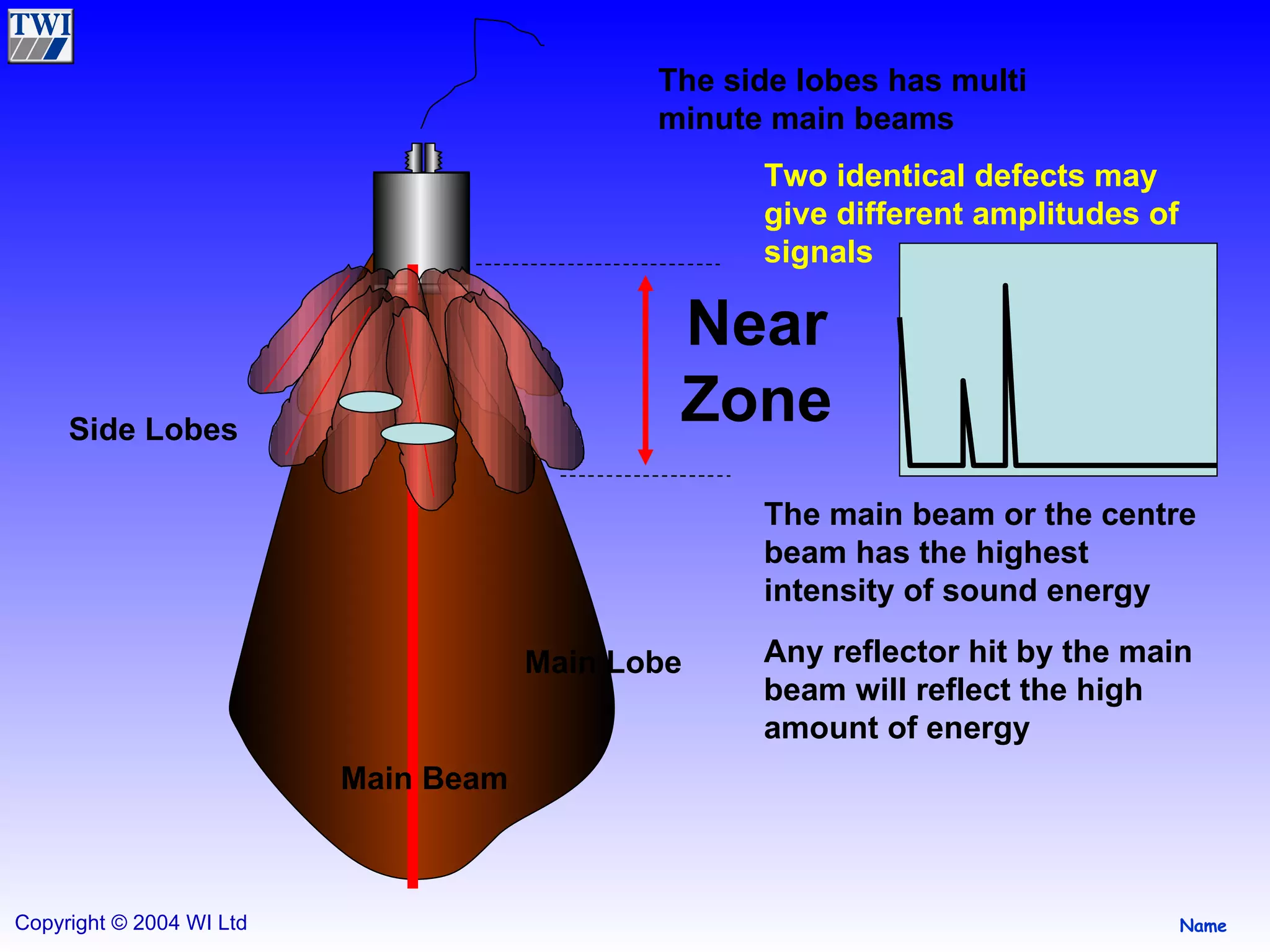
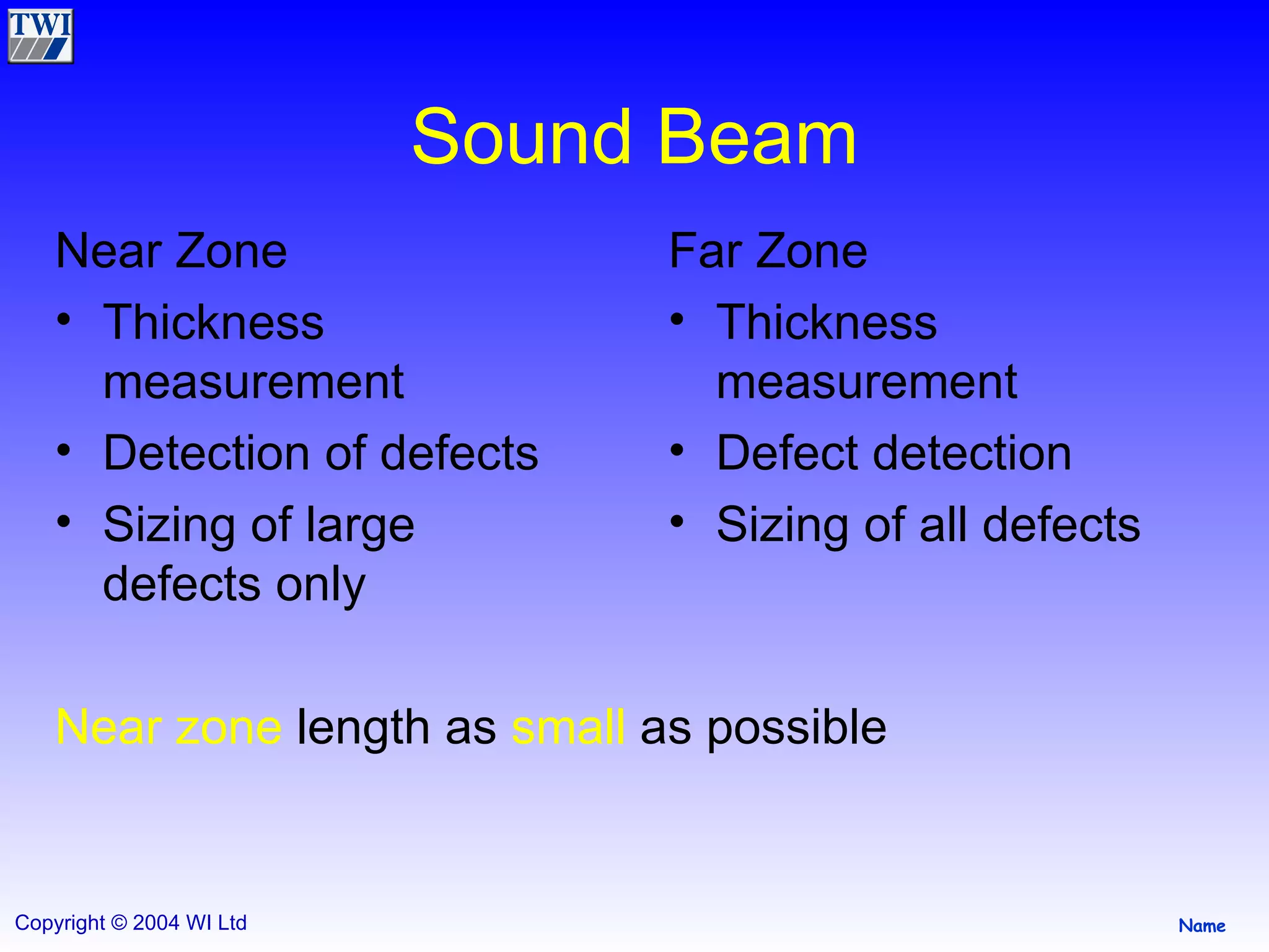
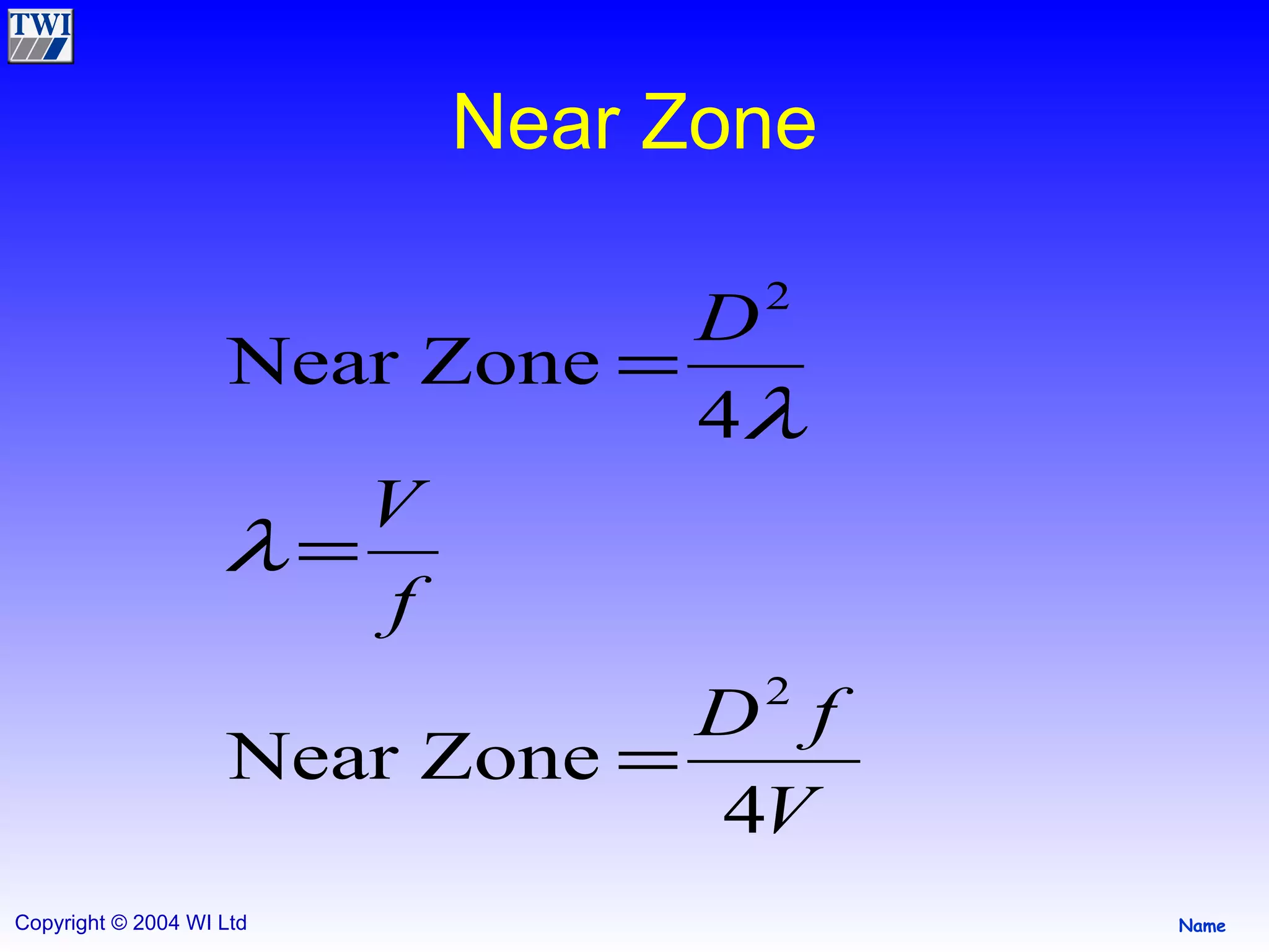
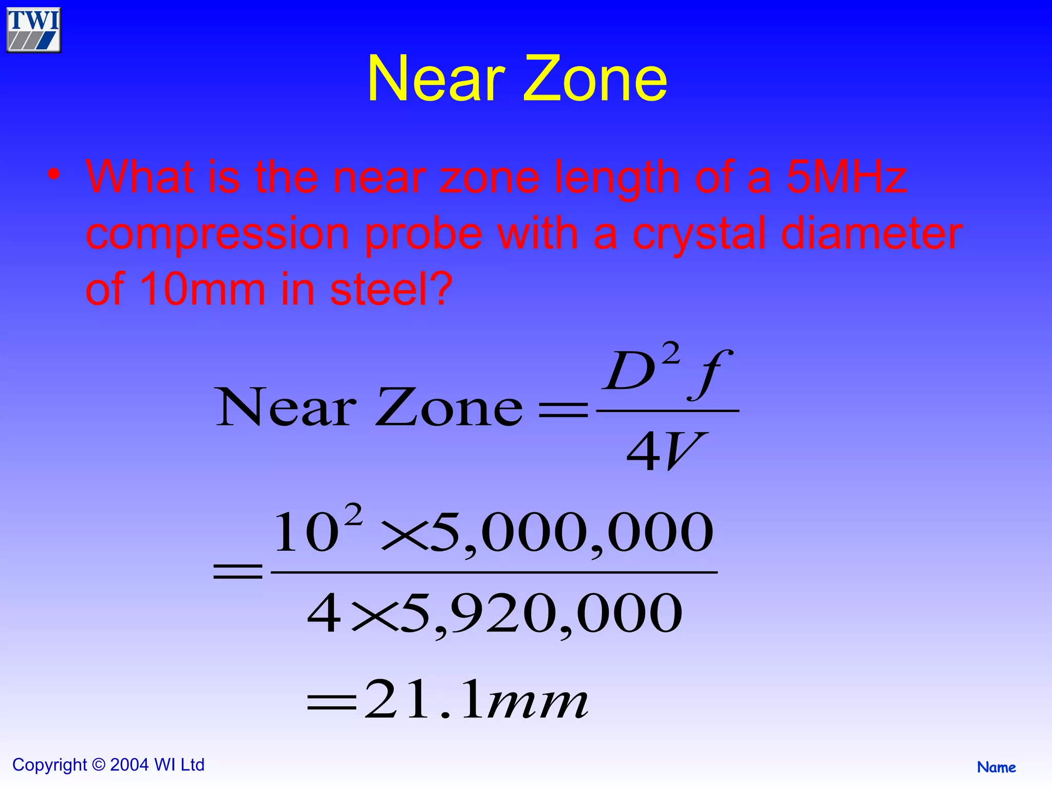
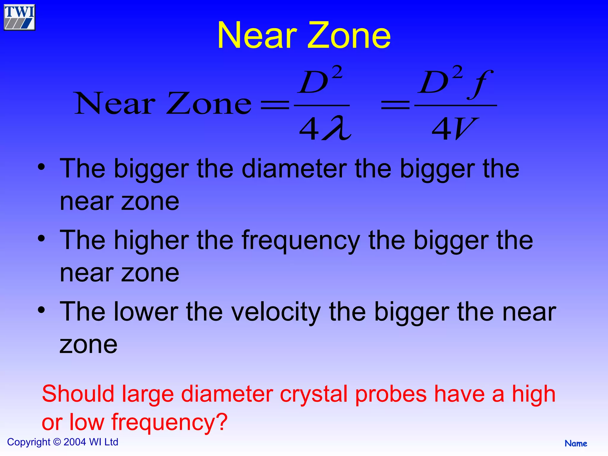
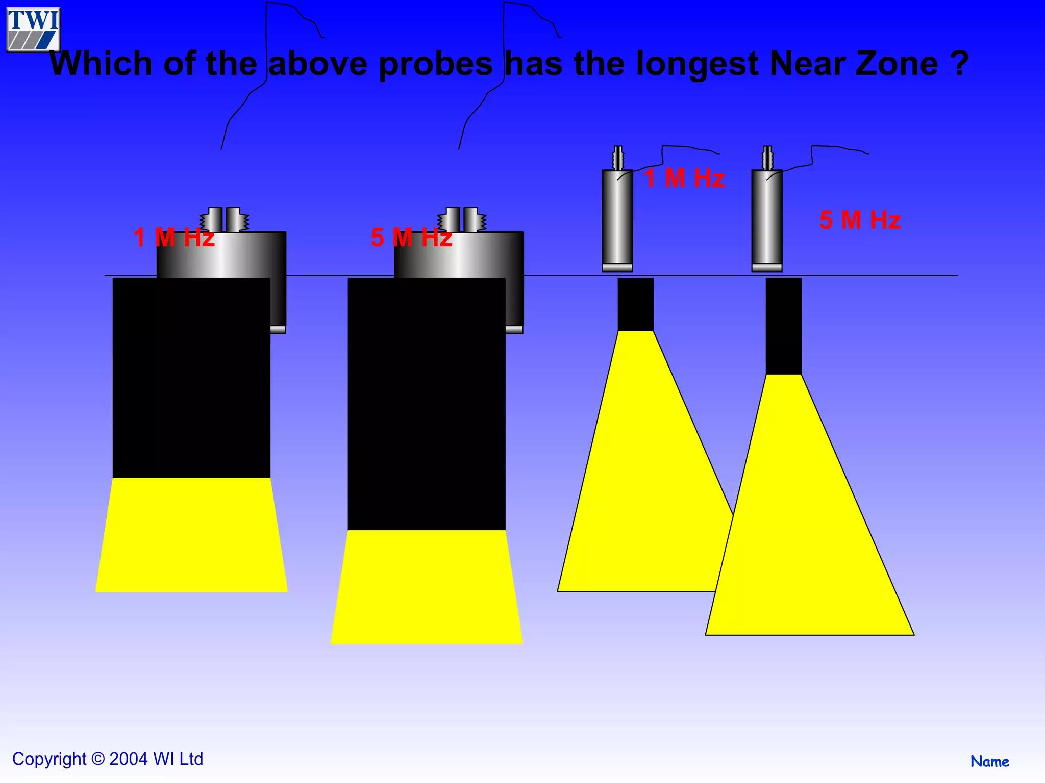
2) The sound beam has a near zone where intensity varies and a far zone with exponential decay. The near zone length depends on probe frequency and diameter, with higher frequency and larger diameter increasing length.
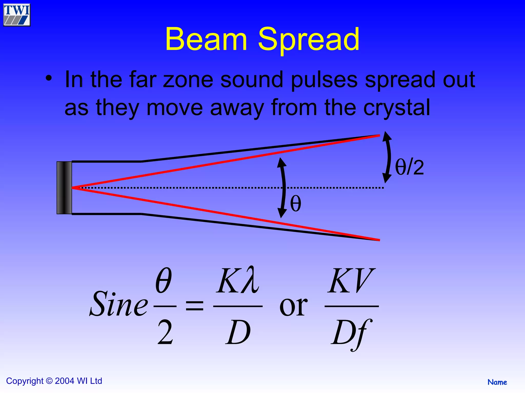
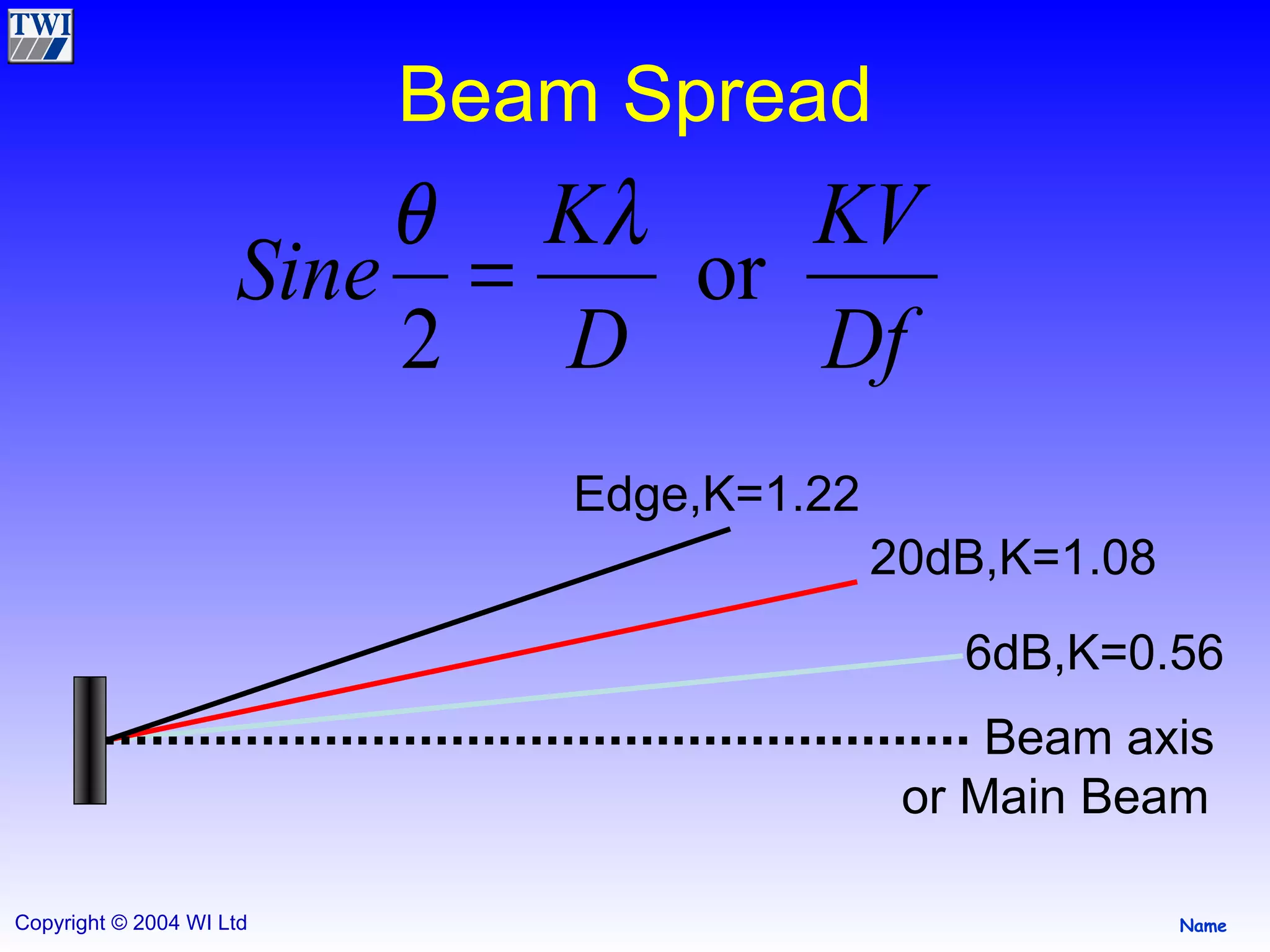
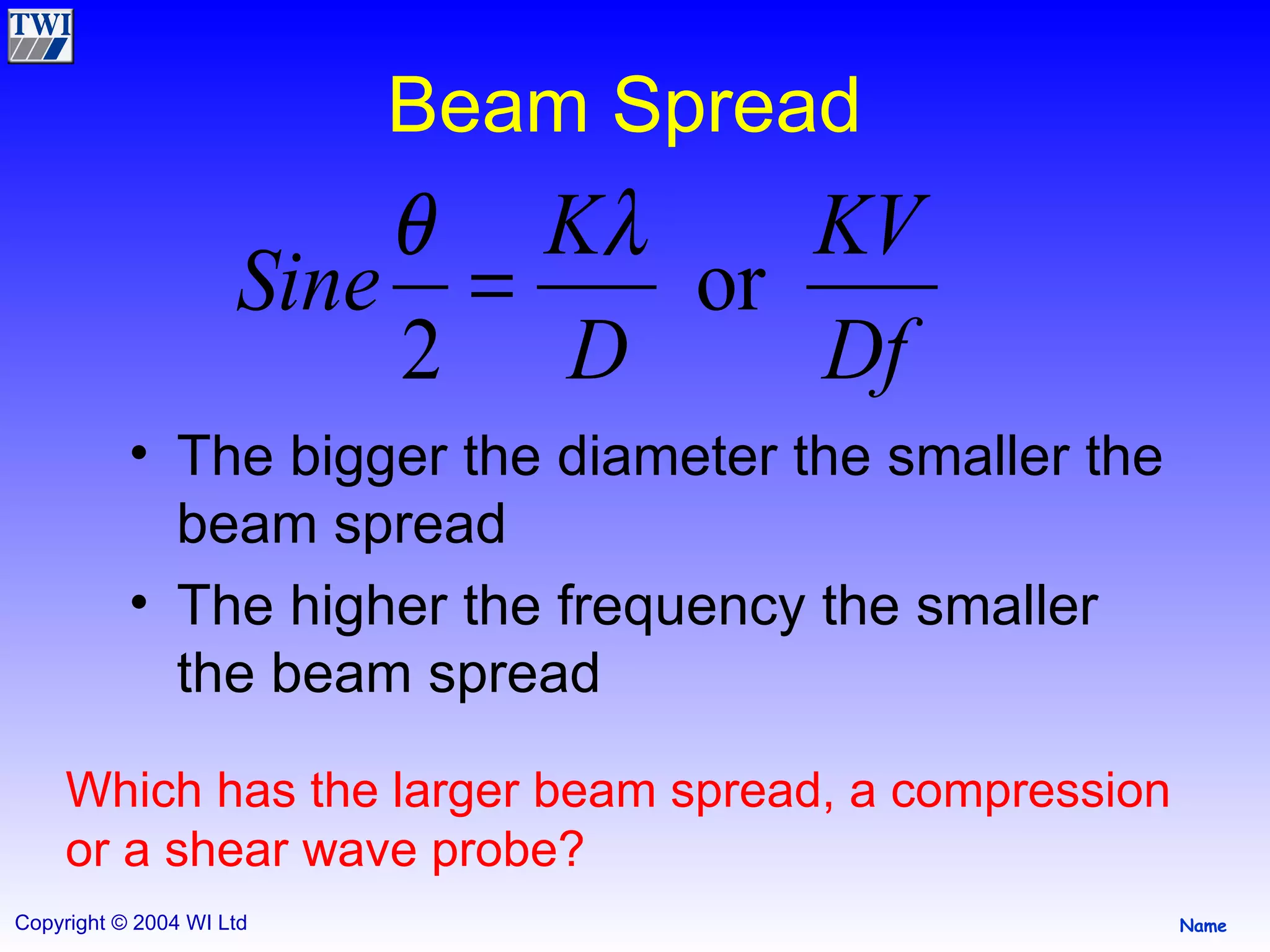
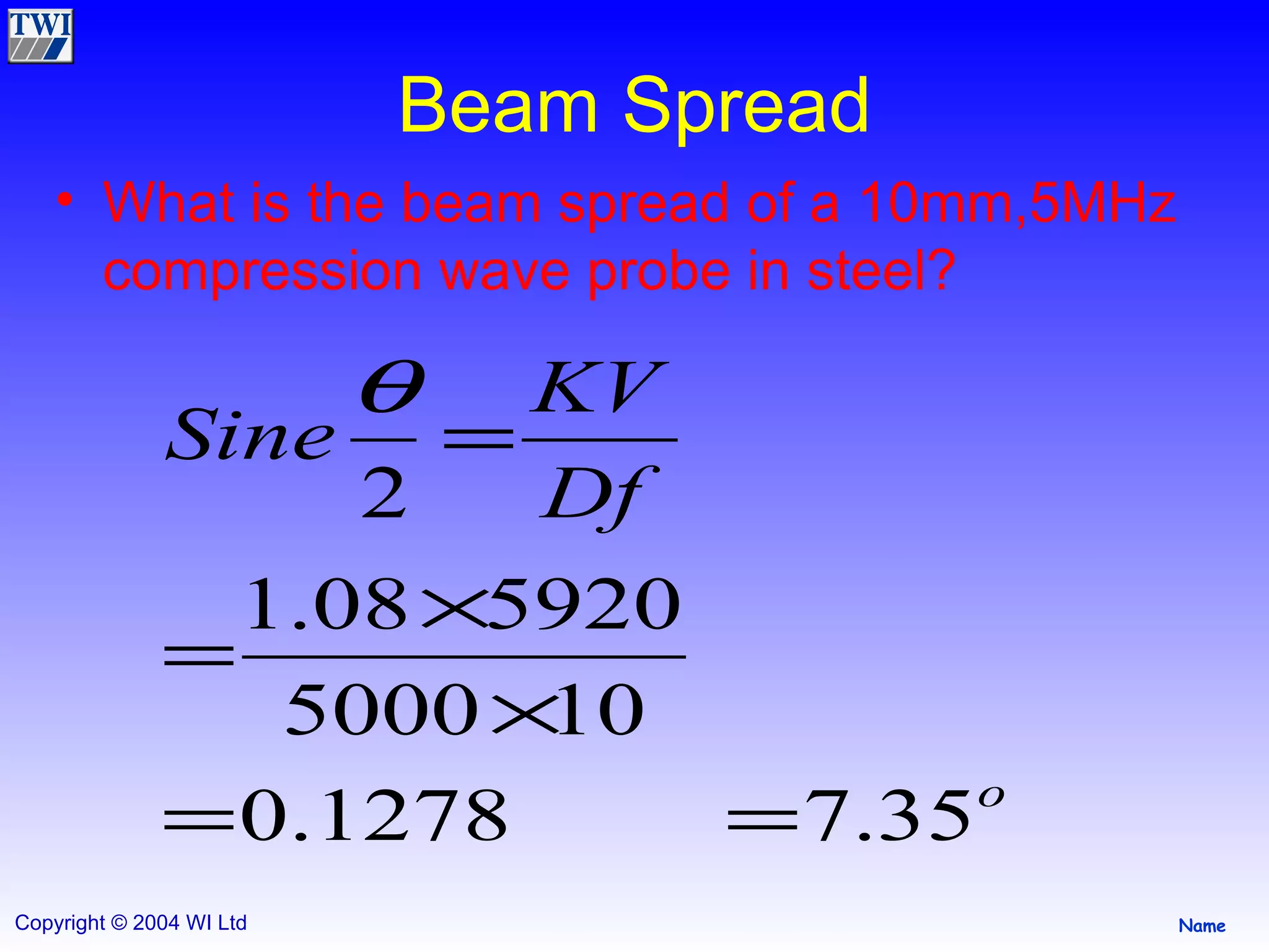
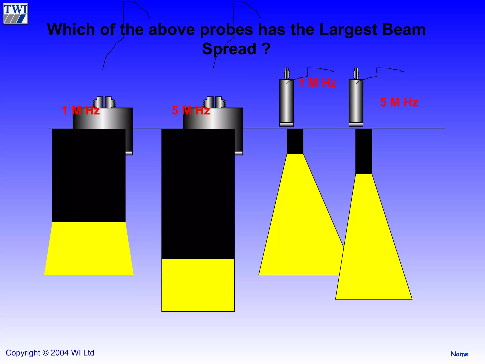
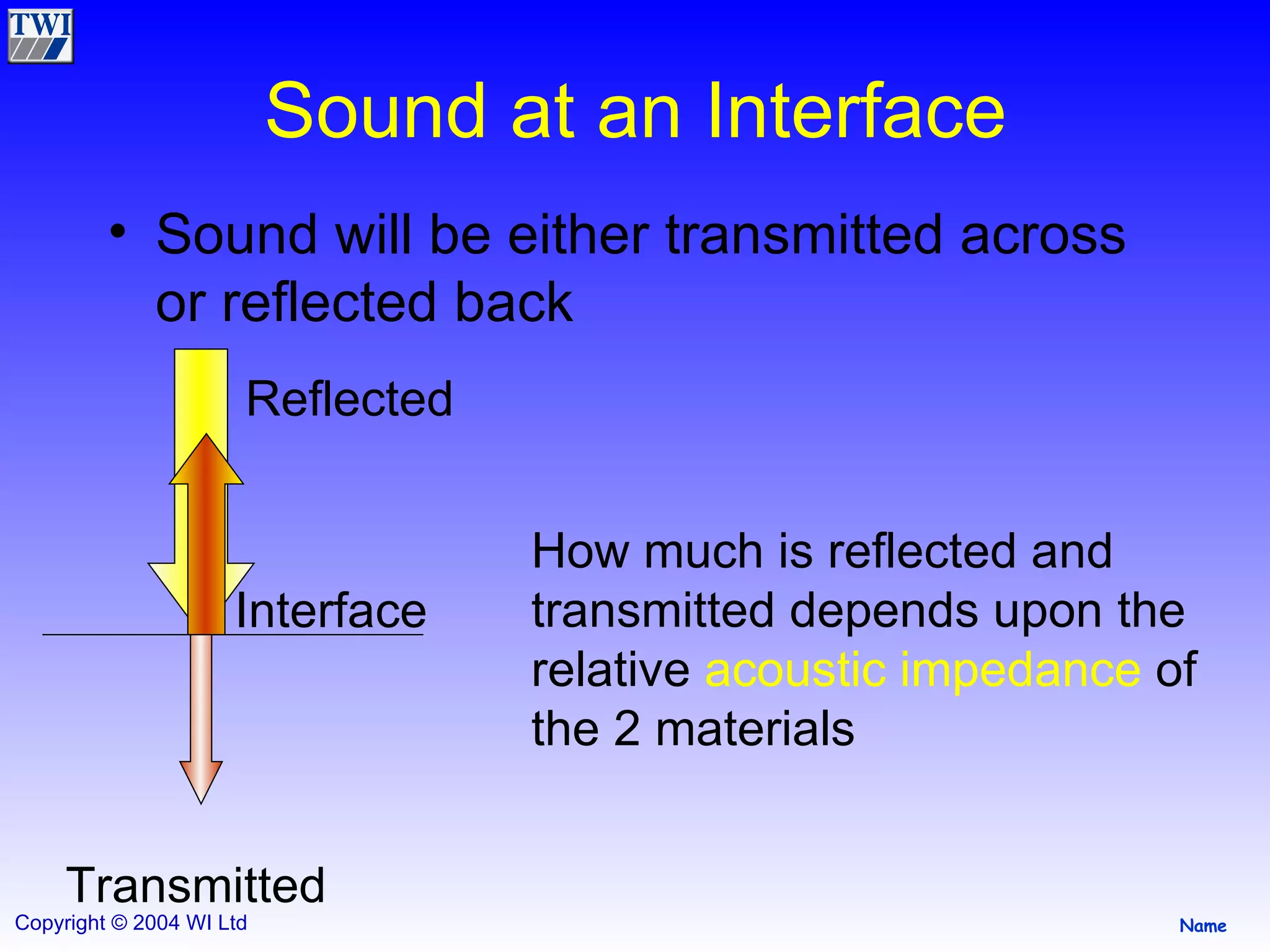
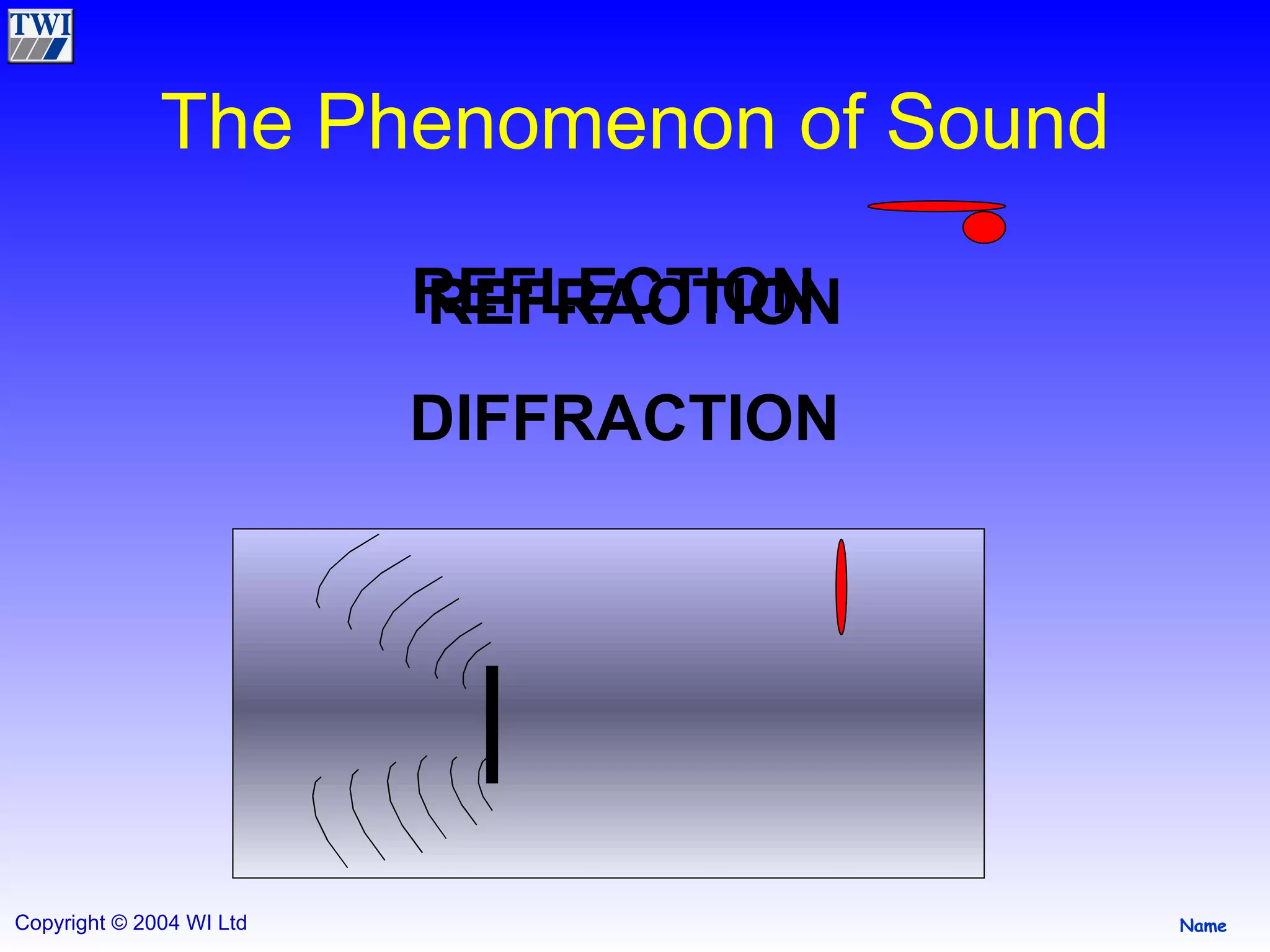
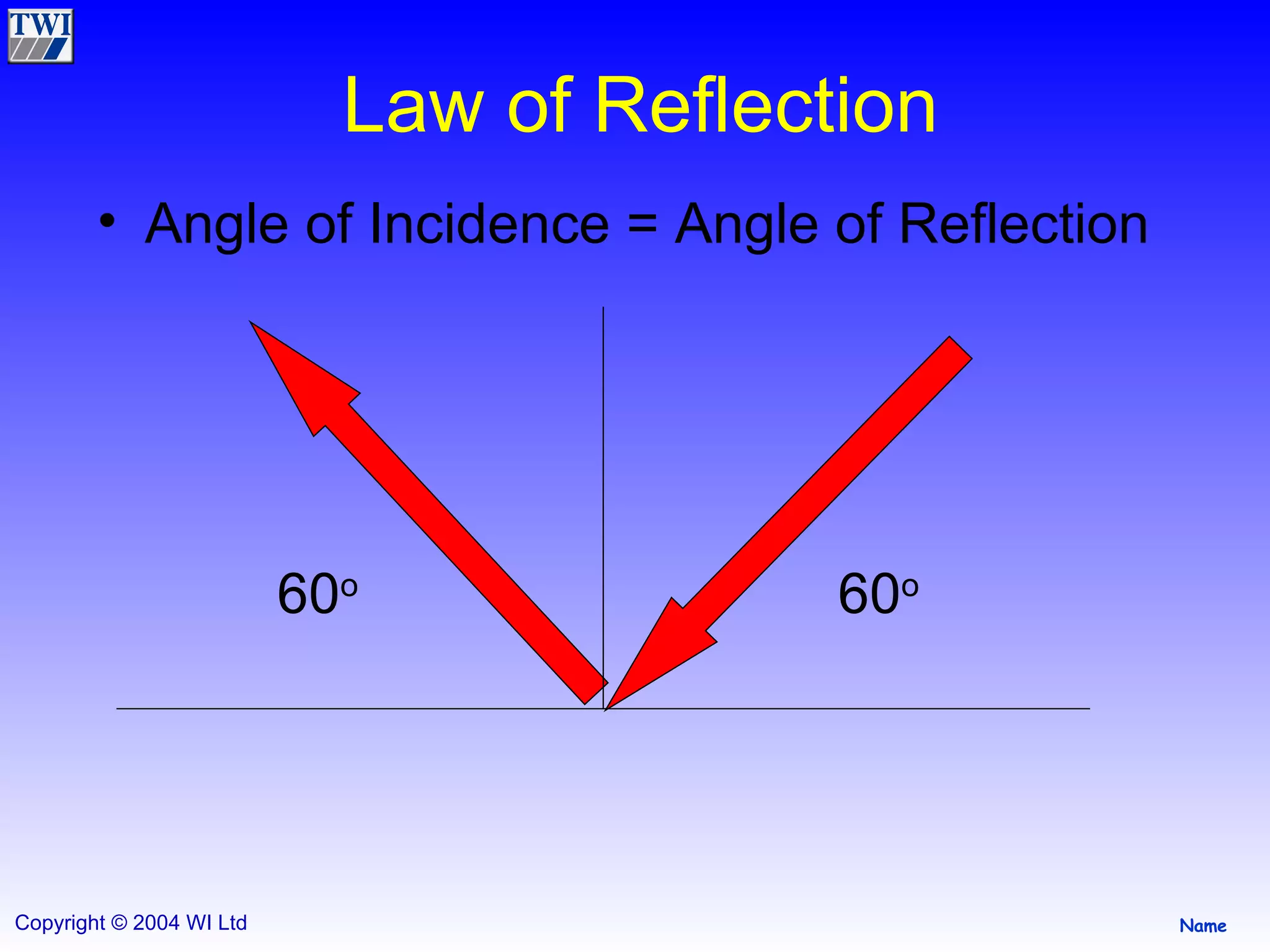
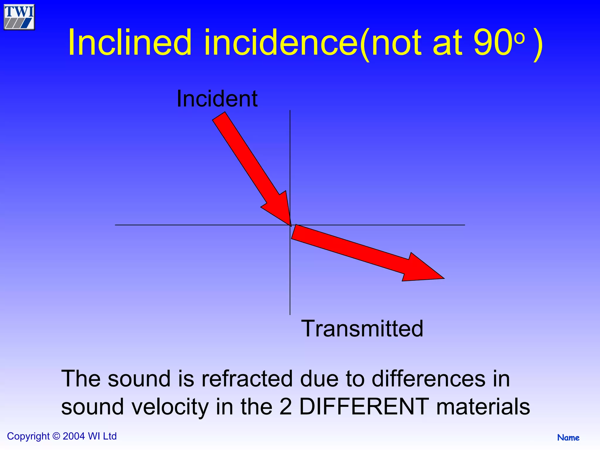
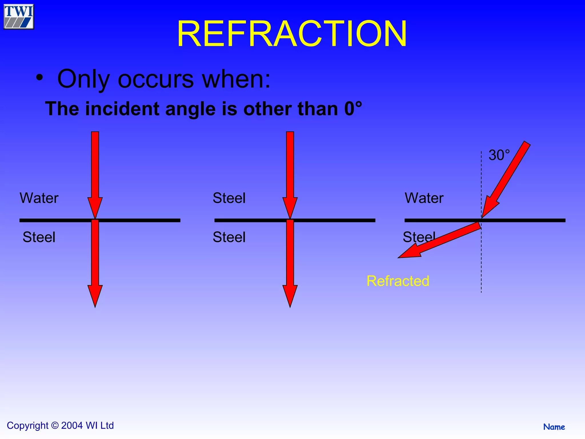
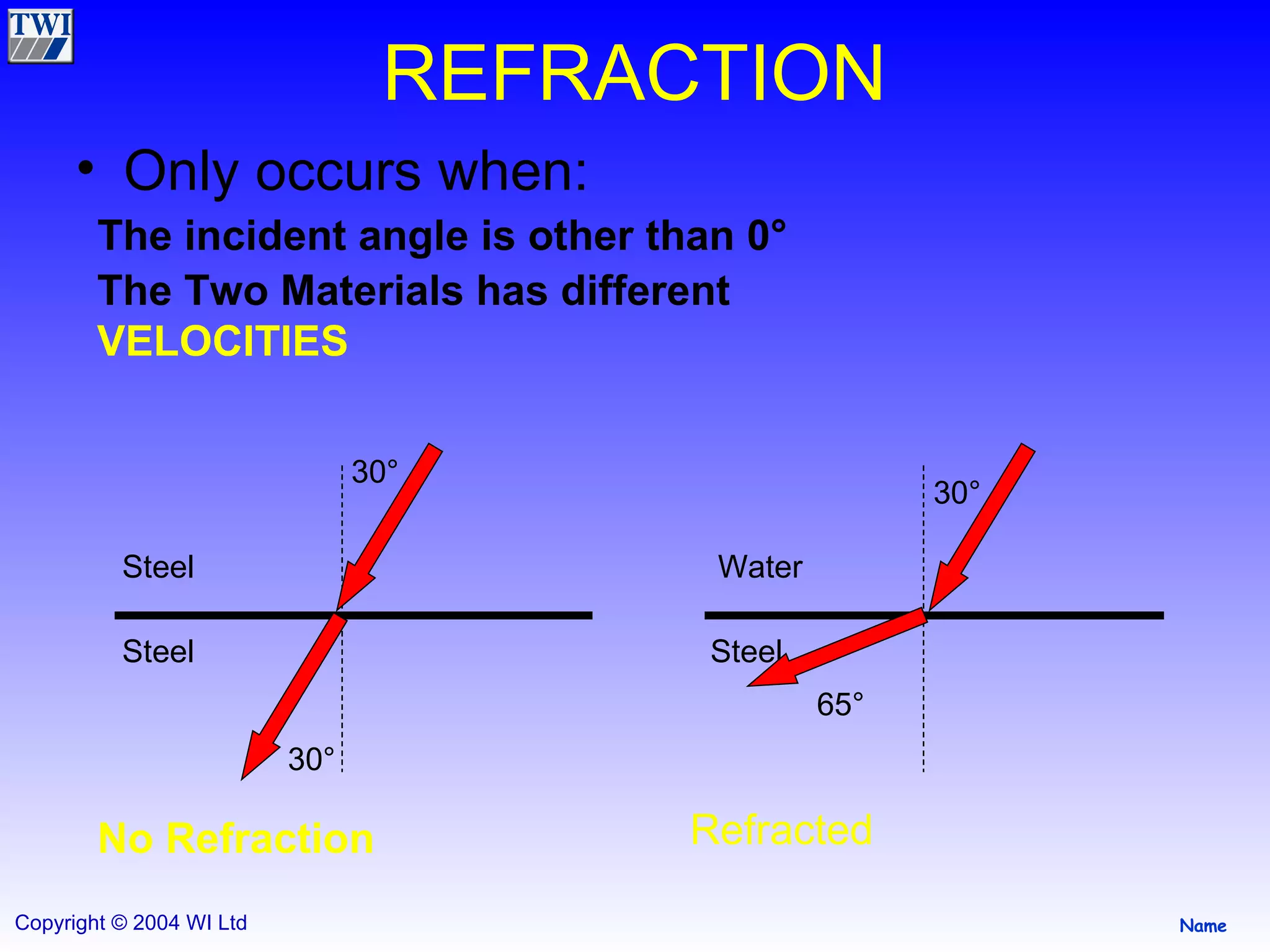
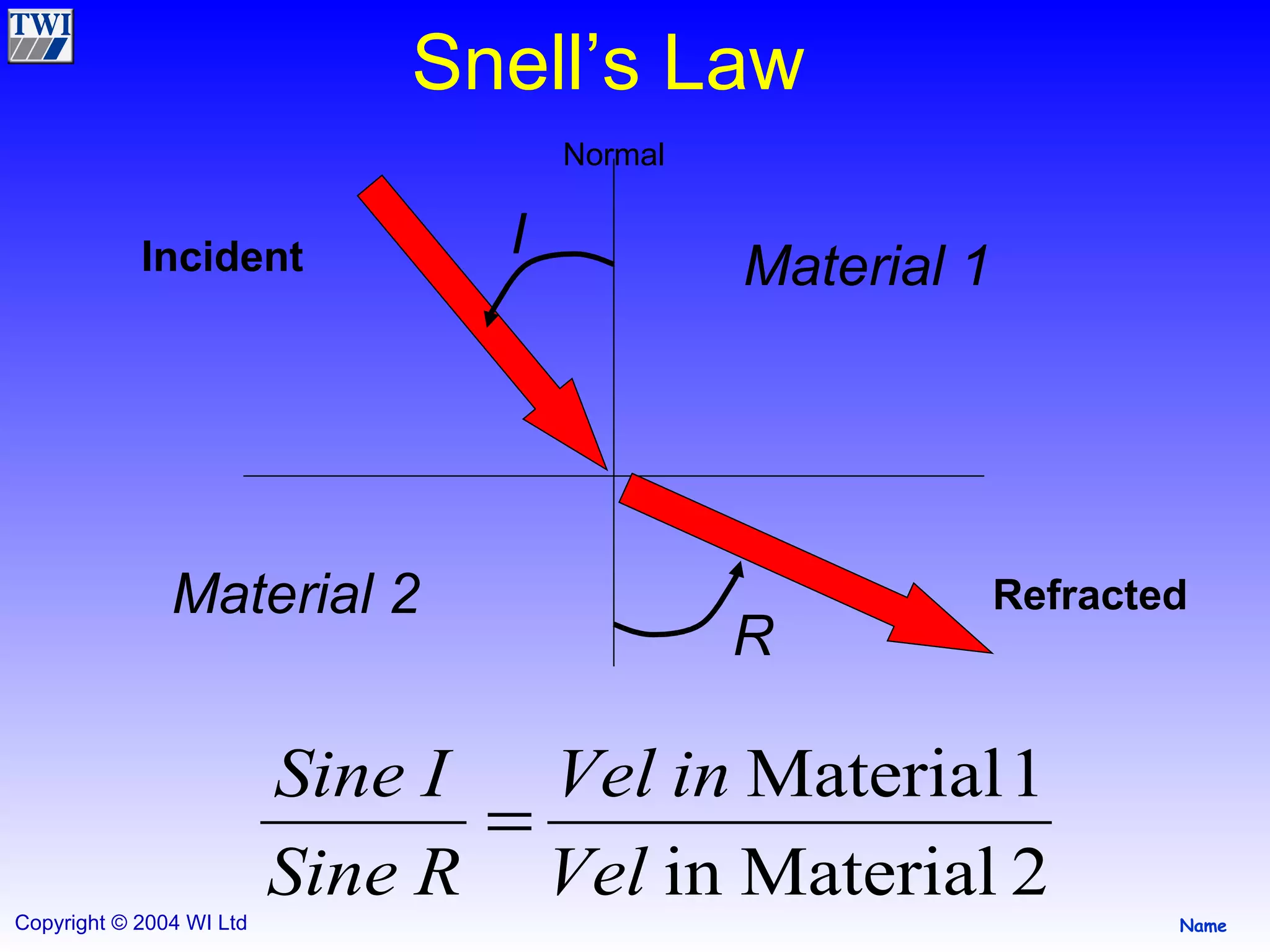
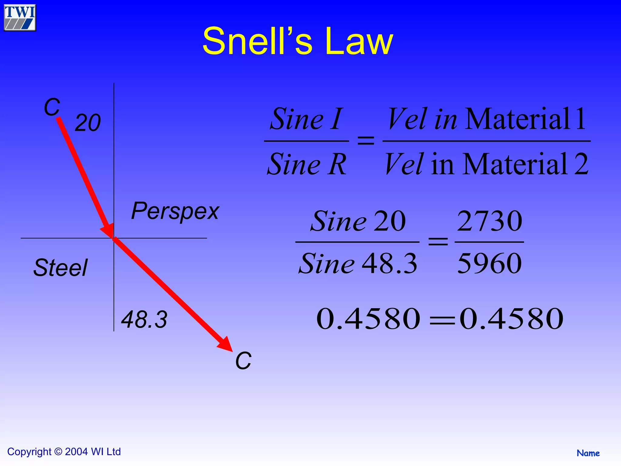
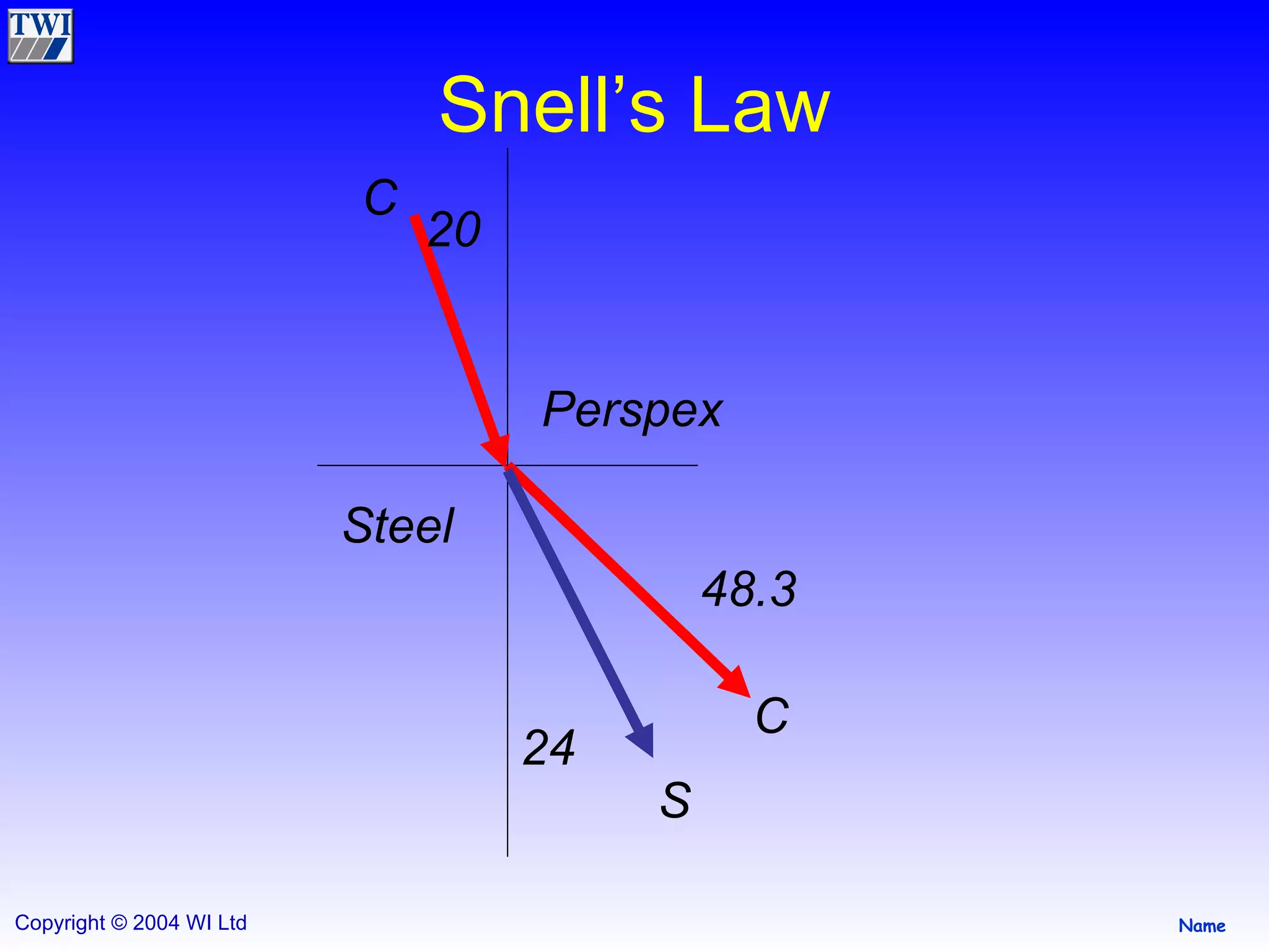
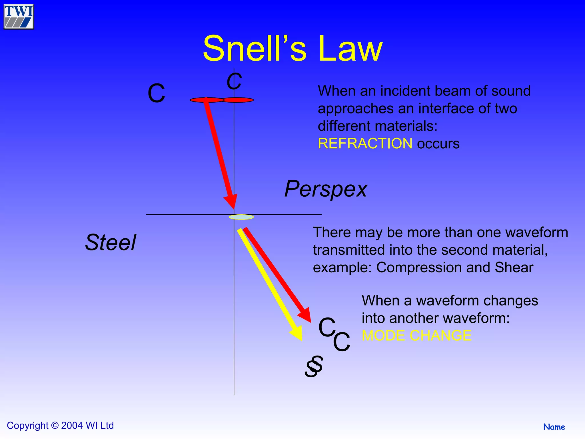
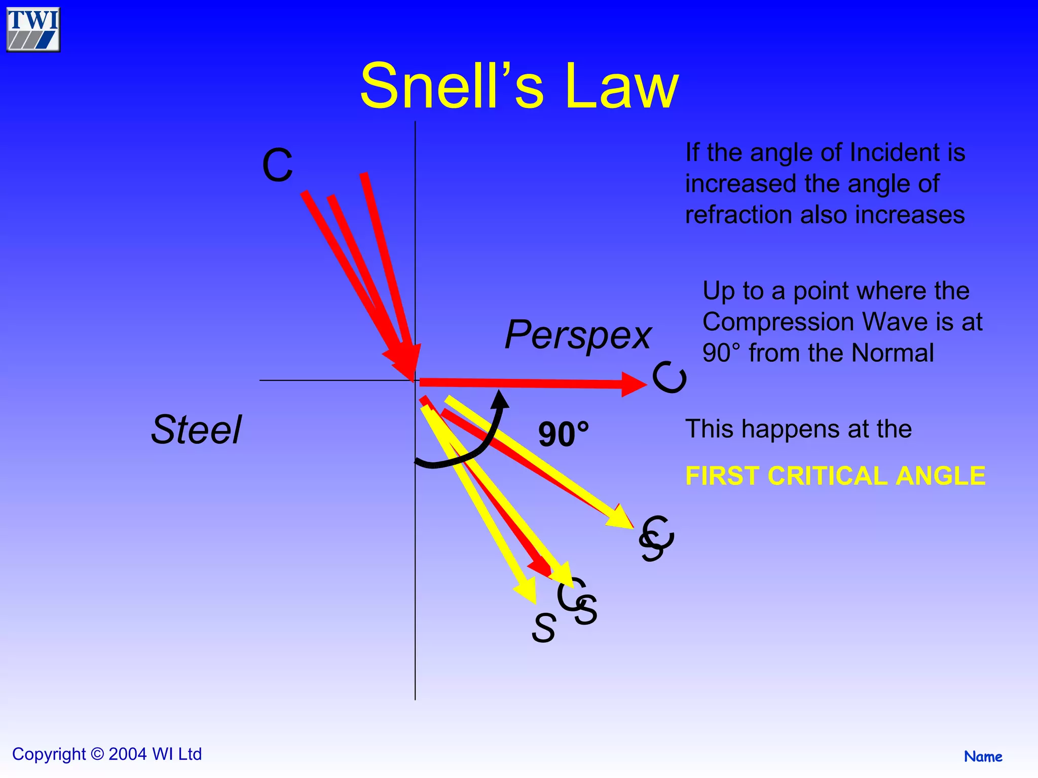
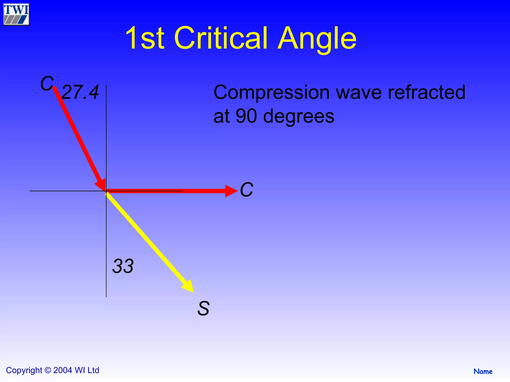
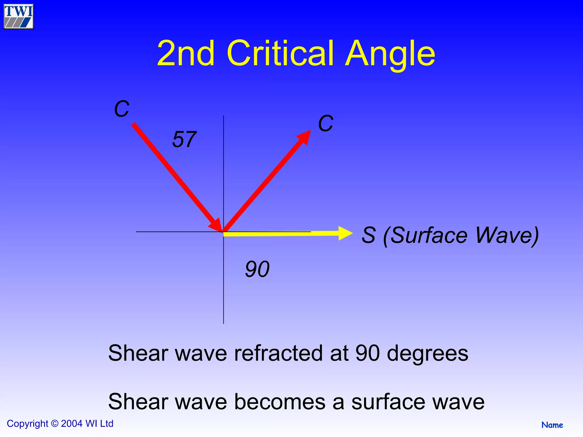
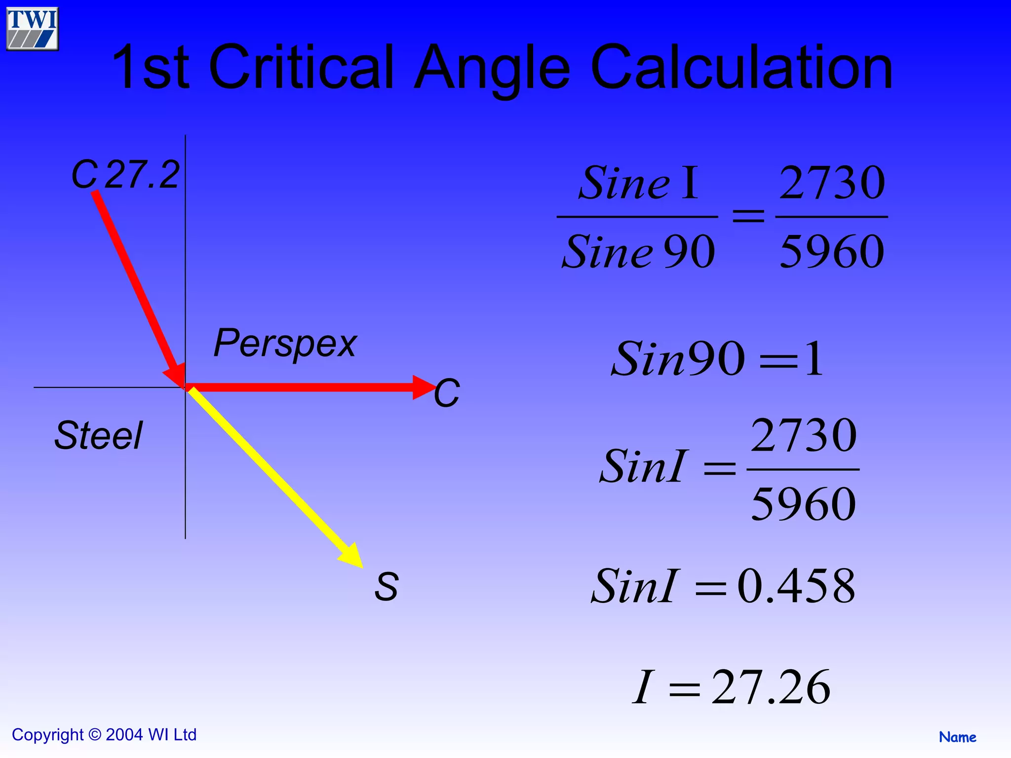
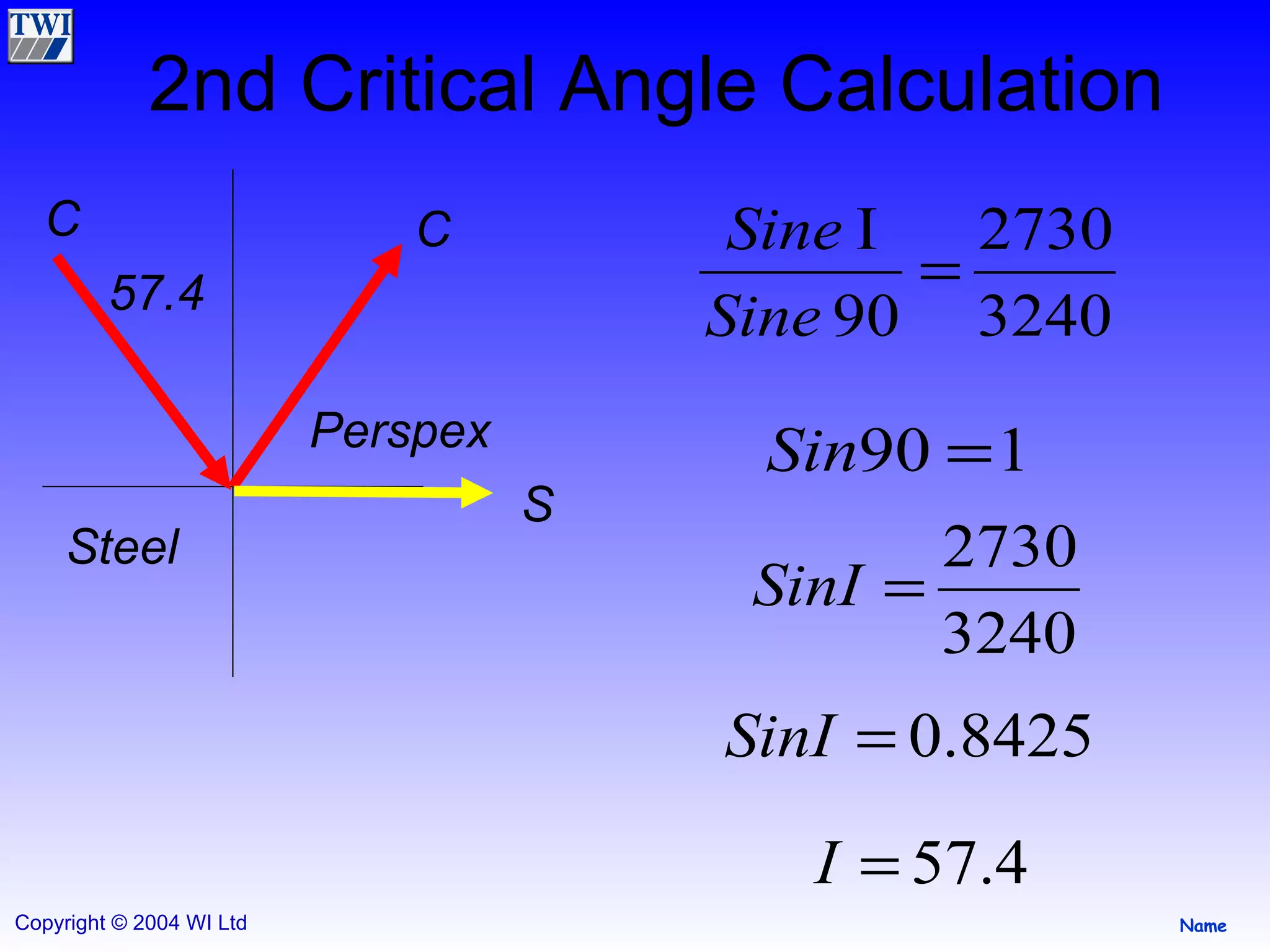
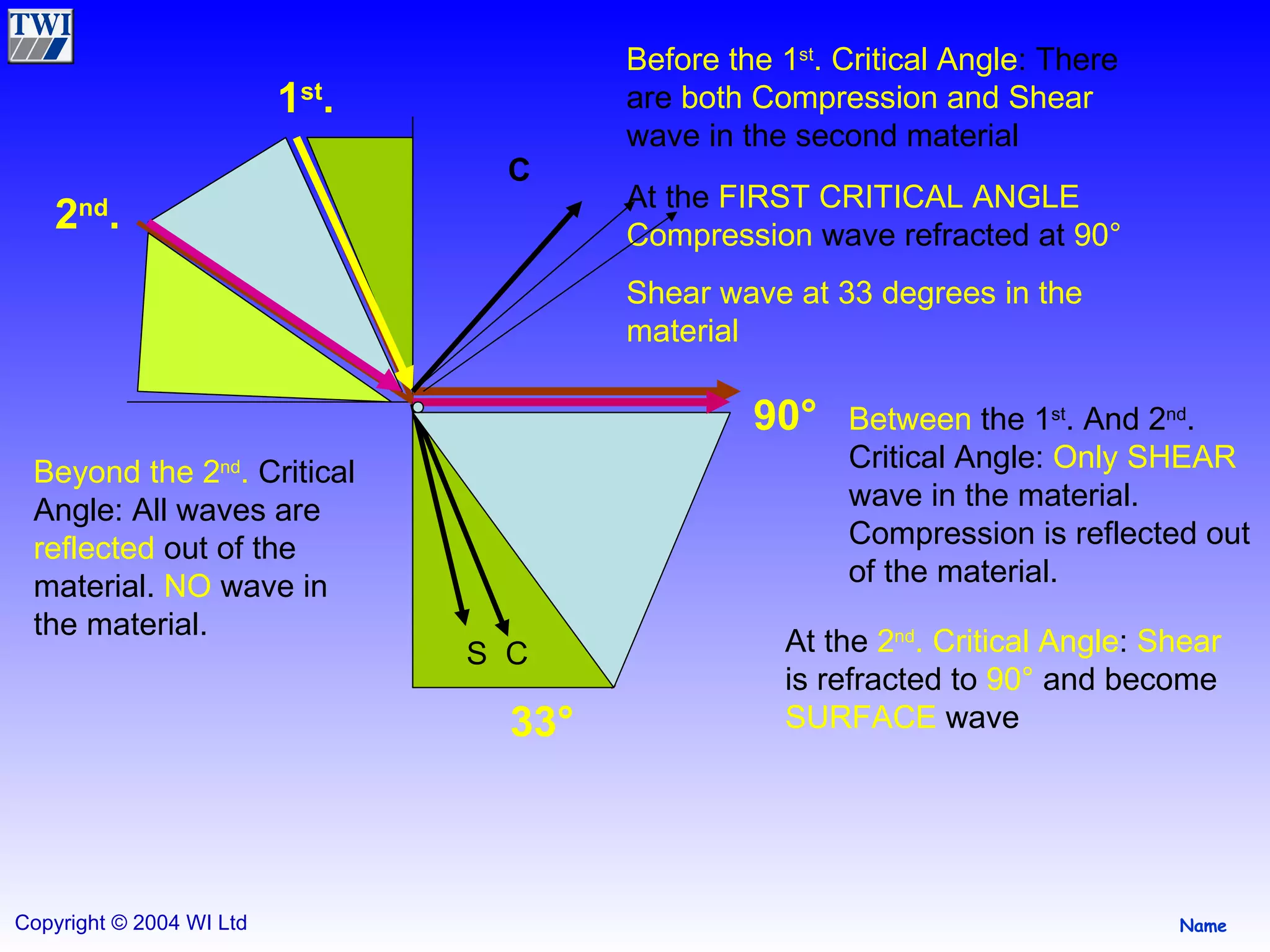
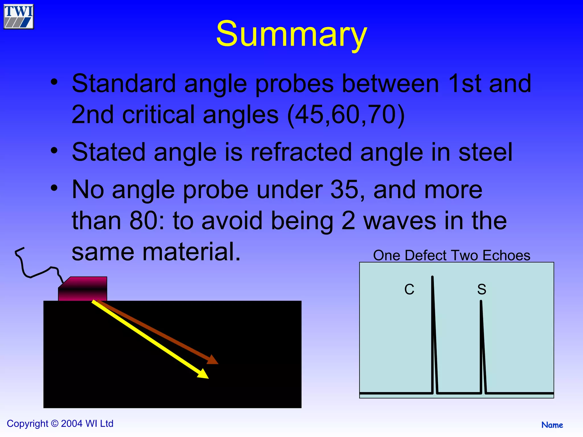
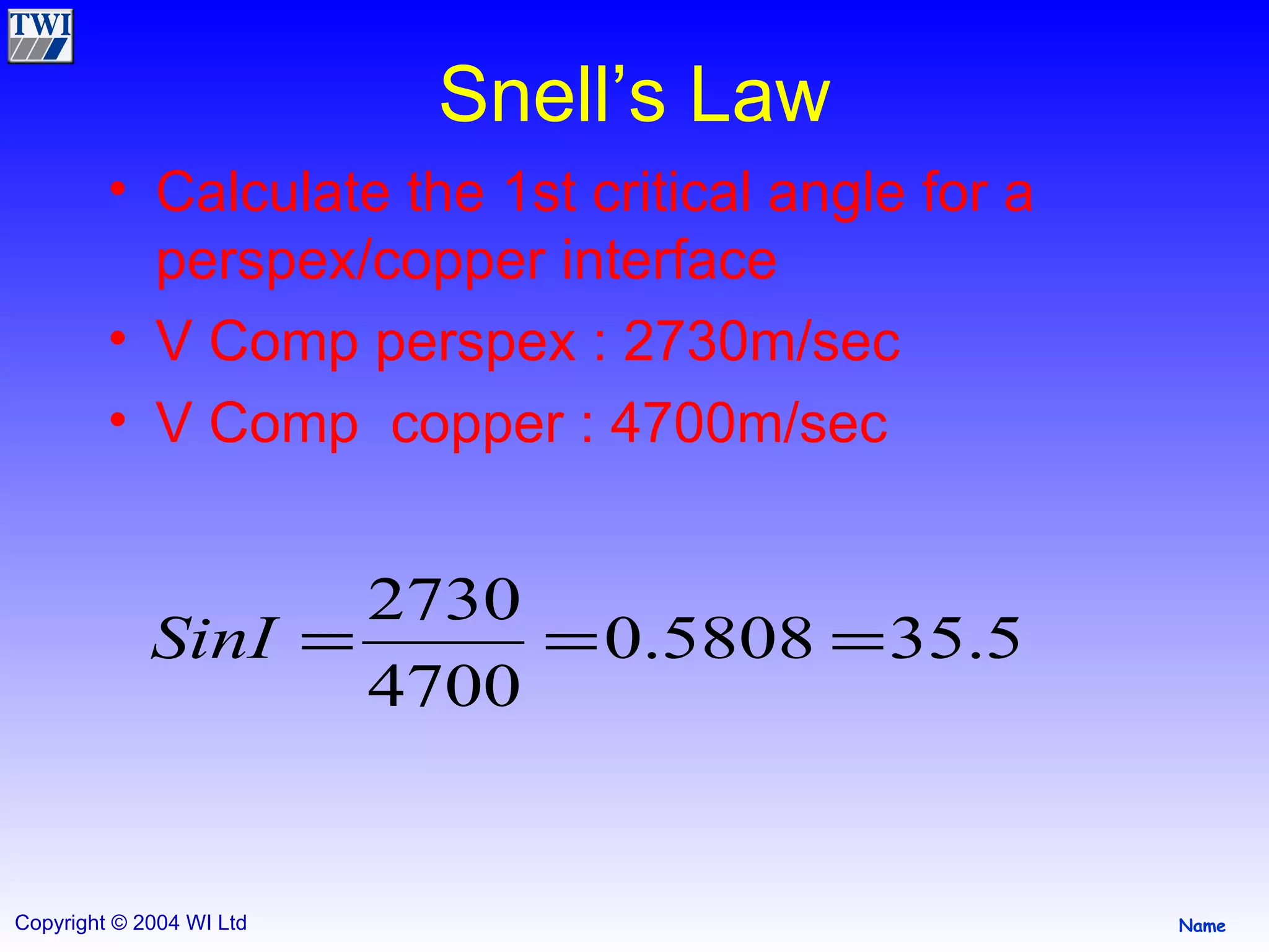
3) Beam spread is smaller with higher frequency and larger diameter probes. Compression waves have a smaller beam spread than shear waves. Snell's law and critical angles determine how sound refracts between materials