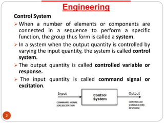
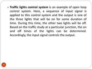
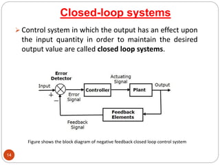
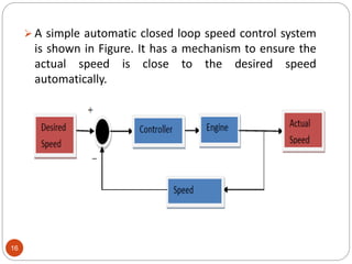
Gfe Mayur Vihar Call Girls Service WhatsApp -> 9999965857 Available 24x7 ^ De...
UNIT 1 CSE NEW.PPTX
1. UNIT – I
CONTROL SYSTEM
ENGINEERING
Prepared by D.Balaji
AP/EEE/MVIT
1
2. Engineering
2
Control System
When a number of elements or components are
connected in a sequence to perform a specific
function, the group thus form is called a system.
In a system when the output quantity is controlled by
varying the input quantity, the system is called control
system.
The output quantity is called controlled variable or
response.
The input quantity is called command signal or
excitation.
3. Classification of Control Systems
3
The Control System can be classified mainly depending
upon,
(a) Method of analysis & design, as Linear & Non-
Linear Systems.
(b)The type of the signal, as Time Varying, Time
Invariant, Continuous data, Discrete data systems
etc.
(c)The type of system components, as Electro
Mechanical, Hydraulic, Thermal, Pneumatic
Control systems etc.
(d)The main purpose, as Position control & Velocity
control Systems
4. 4
Linear & Non -Linear Systems:
A linear system is a mathematical model of a system based on
the use of a linear operator. In a linear system, the principle of
superposition can be applied. A nonlinear system is a system in
which the change of the output is not proportional to the
change of the input.
Time Varying & Time Invariant Systems:
While operating a control system, if the parameters are
unaffected by the time, then the system is called Time
Invariant Control System.
Most physical systems have parameters changing with time. If
this variation is measurable during the system operation then
the system is called Time Varying System.
If there is no non-linearity in the time varying system, then the
system may be called as Linear Time varying System.
5. 5
Continuous time and Discrete-time Control Systems
Control Systems can be classified as continuous time control
systems and discrete time control systems based on the type
of the signal used.
In continuous time control systems, all the signals are
continuous in time. But, in discrete time control systems,
there exists one or more discrete time signals.
SISO and MIMO Control Systems
Control Systems can be classified as SISO control systems and
MIMO control systems based on the number of inputs and
outputs present.
SISO (Single Input and Single Output) control systems have
one input and one output. Whereas, MIMO (Multiple Inputs
and Multiple Outputs) control systems have more than one
input and more than one output.
6. System
6
Figure shows the basic components of a feed back control system.
It consists of an input (objective), system (plant), sensor (feedback element),
controller and output (result).
7. 7
Feedback :The portion of the output of a system that is returned to modify the
input and thus serve as a performance monitor for the system. The element
present in feedback path is feedback element. Mostly sensor are used for
feedback elements in most of control system.
Error Detector: The difference between the input stimulus and the output
response is called error. Specifically, it is the difference between the input and
the feedback signal. The error signal generated by using error detector.
8. 8
This sensor would monitor the actual dryness of the clothes and compare it
with (or subtract it from) the input reference. The error signal (error =
required dryness – actual dryness) is amplified by the controller, and the
controller output makes the necessary correction to the heating system to
reduce any error. For example if the clothes are too wet the controller may
increase the temperature or drying time. Likewise, if the clothes are nearly
dry it may reduce the temperature or stop the process so as not to overheat
or burn the clothes, etc.
Comparison of basic Components of Control System with example
9. 9
Any physical system which does not automatically
correct the variation in its output is called an open loop
system, or control system in which the output quantity
has no effect upon the input quantity are called open-
loop control system.
The open-loop system is also called the non-feedback
system.
Practically our day-to-day activities are affected by some
type of control systems. There are two main branches of
control systems:
1) Open-loop systems and
2) Closed-loop systems
OPEN LOOP CONTROL SYSTEM
10. 10
Examples − Open loop speed control of an automobile & Traffic
lights control system
In this open-loop system, there is no way to ensure the actual
speed is close to the desired speed automatically. The actual
speed might be way off the desired speed because of the wind
speed and/or road conditions, such as uphill or downhill etc.
BLOCK DIAGRAM OF OPEN LOOP
SYSTEM
11. 11
Traffic lights control system is an example of open loop
control system. Here, a sequence of input signal is
applied to this control system and the output is one of
the three lights that will be on for some duration of
time. During this time, the other two lights will be off.
Based on the traffic study at a particular junction, the on
and off times of the lights can be determined.
Accordingly, the input signal controls the output.
12. 12
Practical Examples of Open Loop Control System
Electric Hand Drier - Hot air (output) comes out as long as you
keep your hand under the machine, irrespective of how much
your hand is dried.
Automatic Washing Machine - This machine runs according to
the pre-set time irrespective of washing is completed or not.
Bread Toaster - This machine runs as per adjusted time
irrespective of toasting is completed or not.
Automatic Tea/Coffee Maker - These machines also function
for pre adjusted time only.
Timer Based Clothes Drier - This machine dries wet clothes for
pre-adjusted time, it does not matter how much the clothes
are dried.
Light Switch - Lamps glow whenever light switch is on
irrespective of light is required or not.
Volume on Stereo System - Volume is adjusted manually
irrespective of output volume level.
13. 13
Advantages of Open Loop Control System
Simple in construction and design.
Economical.
Easy to maintain.
Generally stable.
Convenient to use as output is difficult to measure.
Disadvantages of Open Loop Control System
They are inaccurate.
They are unreliable.
Any change in output cannot be corrected
automatically.
14. 14
Control system in which the output has an effect upon
the input quantity in order to maintain the desired
output value are called closed loop systems.
Closed-loop systems
Figure shows the block diagram of negative feedback closed loop control system
15. 15
The error detector produces an error signal, which is the
difference between the input and the feedback signal. This
feedback signal is obtained from the block (feedback
elements) by considering the output of the overall system
as an input to this block. Instead of the direct input, the
error signal is applied as an input to a controller.
So, the controller produces an actuating signal which
controls the plant. In this combination, the output of the
control system is adjusted automatically till we get the
desired response. Hence, the closed loop control systems
are also called the automatic control systems. Traffic lights
control system having sensor at the input is an example of
a closed loop control system.
16. 16
A simple automatic closed loop speed control system
is shown in Figure. It has a mechanism to ensure the
actual speed is close to the desired speed
automatically.
17. 17
Practical Examples of Closed Loop Control System
Automatic Electric Iron - Heating elements are controlled
by output temperature of the iron.
Servo Voltage Stabilizer - Voltage controller operates
depending upon output voltage of the system.
Water Level Controller - Input water is controlled by
water level of the reservoir.
Missile Launched and Auto Tracked by Radar - The
direction of missile is controlled by comparing the target
and position of the missile.
An Air Conditioner - An air conditioner functions
depending upon the temperature of the room.
Cooling System in Car - It operates depending upon the
temperature which it controls.
18. 18
Advantages of Closed Loop Control System
Closed loop control systems are more accurate even in the
presence of non-linearity.
Highly accurate as any error arising is corrected due to presence
of feedback signal.
Bandwidth range is large.
Facilitates automation.
The sensitivity of system may be made small to make system
more stable.
This system is less affected by noise.
Disadvantages of Closed Loop Control System
They are costlier.
They are complicated to design.
Required more maintenance.
Feedback leads to oscillatory response.
Overall gain is reduced due to presence of feedback.
21. Mathematical model of control
systems
21
A control system is collection of physical objects
(components) connected together to serve an
objective. The input output relations of various
physical components of a system are governed by
differential equations.
The mathematical model of a control system
constitutes a set of differential equations. The
response or output of the system can be studied by
solving the differential equations for various input
conditions.
The mathematical model of a system is linear if it
obeys the principle of superposition and homogeneity.
24. 24
Definition of Transfer Function:
Transfer function of a system is defined as the ratio of the Laplace Transform
of the output variable to the Laplace Transform of the input variable assuming all the
initial condition as zero.
Properties of the Transfer Function :
The transfer function of a system is the mathematical model expressing the
differential equation that relates the output to input of the system.
The transfer function is defined only for linear time invariant systems. It is not
defined for non-linear systems.
The transfer function is the property of a system independent of magnitude and the
nature of the input.
The transfer function includes the transfer functions of the individual elements. But
at the same time, it does not provide any information regarding physical structure of
the system.
If the transfer functions of the system is known, the output response can be studied
for various types of inputs to understand the nature of the system.
If the transfer function is unknown, it may be found out experimentally by applying
known inputs to the device and studying the output of the system.
The system poles/zeros can be found out from transfer function.
25. 25
The features of the transfer functions are,
It is applicable to Linear Time Invariant system.
It is the ratio between the Laplace Transform of
the o/p variable to the Laplace Transform of the i/p
variable.
It is assumed that initial conditions are zero.
It is independent of i/p excitation.
It is used to obtain systems o/p response.
26. Advantages and disadvantages of
transfer function
26
Advantages :-
1. It is a mathematical model that gives the gain of the given
block/system.
2. Integral and differential equations are converted to simple
algebraic equations.
3. Once the transfer function is known, any output for any
given input, can be known.
4. System differential equation can be obtained by
replacement of variable ‘s’ by ‘d/dt’
5. The value of transfer function is dependent on the
parameters of the system and independent of the
input applied.
27. 27
Disadvantages :-
1. Transfer function is valid only for Linear Time Invariant
systems.
2. It does not take into account the initial conditions. Initial
conditions loose their significance.
3. It does not give any idea about how the present output is
progressing.