Download as PDF, PPTX


![References
1. Gonzales, Divina R. (n.d.) Simple Stress [Class Handout].
Mechanics of Deformable Bodies, Mapúa Institute of
Technology, Intrauros, Manila.
2. Philpot, Timothy A. (2008). Mechanics of Materials: An
Integrated Learning System. USA: John Wiley & Sons, Inc.
3. Verterra, Romel. (2014). Normal Stresses. Retrieved from
http://www.mathalino.com/reviewer/mechanics-and-
strength-of-materials/normal-stresses](https://image.slidesharecdn.com/mec32-a1-grp1-simplestress-pdf-140427040622-phpapp02/85/Simple-Stress-Normal-Stress-16-320.jpg)

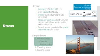
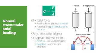
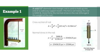
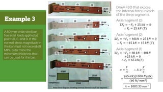
The document covers the mechanics of deformable bodies, focusing on internal effects caused by external loads. It explains concepts such as normal stress, tensile and compressive stress, and their significance in engineering design. Several examples illustrate the calculations of stress under various conditions, emphasizing the importance of understanding material strength and deformation.