This document discusses welded connections that experience eccentric loading. It describes two types of eccentrically loaded connections: those that cause twisting moments and those that cause bending moments. For connections with twisting moments, the document explains how to calculate the direct shear stress, torsional stress, and resultant stress. For connections with bending moments, it provides equations to calculate the direct shear stress, bending stress, and resultant stress for both fillet and groove welds. Finally, it includes two examples problems that demonstrate how to analyze and design eccentrically loaded welded connections.
NAME EMROLLMENT NO.
PATELPRASHANT 141100106078
DESHMUKH BHAVIK 151103106002
KANSARAABHISHEK 151103106007
PATEL NIRMAL 151103106012
GUIDED BY :Asst. Prof. Sunil Jagania Sir
Eccentrically Loaded Connections
Generally the structural members are subjected to the axial loading which is acting
on the central vertical axis of the member.
But sometimes it is possibility that the load acting on the members is not particularly
on its axis but a far distance from its centre.
That distance is considered as the Eccentric Distance and the load acting at that
particular distance apart from its axis is defined as Eccentric Load.
6.
• The weldedjoints subjected to eccentric
load are two types:-
Eccentric Load Causing Twisting Moment
Eccentric Load Causing Bending Moment
7.
(a) Eccentric LoadCausing Twisting Moment
The centre of gravity of the weld lies in the plane of line of action of of the
applied load.
8.
Load Pwill cause direct shear and twisting moment in the weld.
G = Centroid of weld
x̄ and ȳ are the co-ordinates of centroid of the weld
B is the critical point on the weld, x and y are the co-ordinates of the
critical weld point,
r = 𝑥2 + 𝑦2
Stress due to the direct shear,
Pd = P/lw
9.
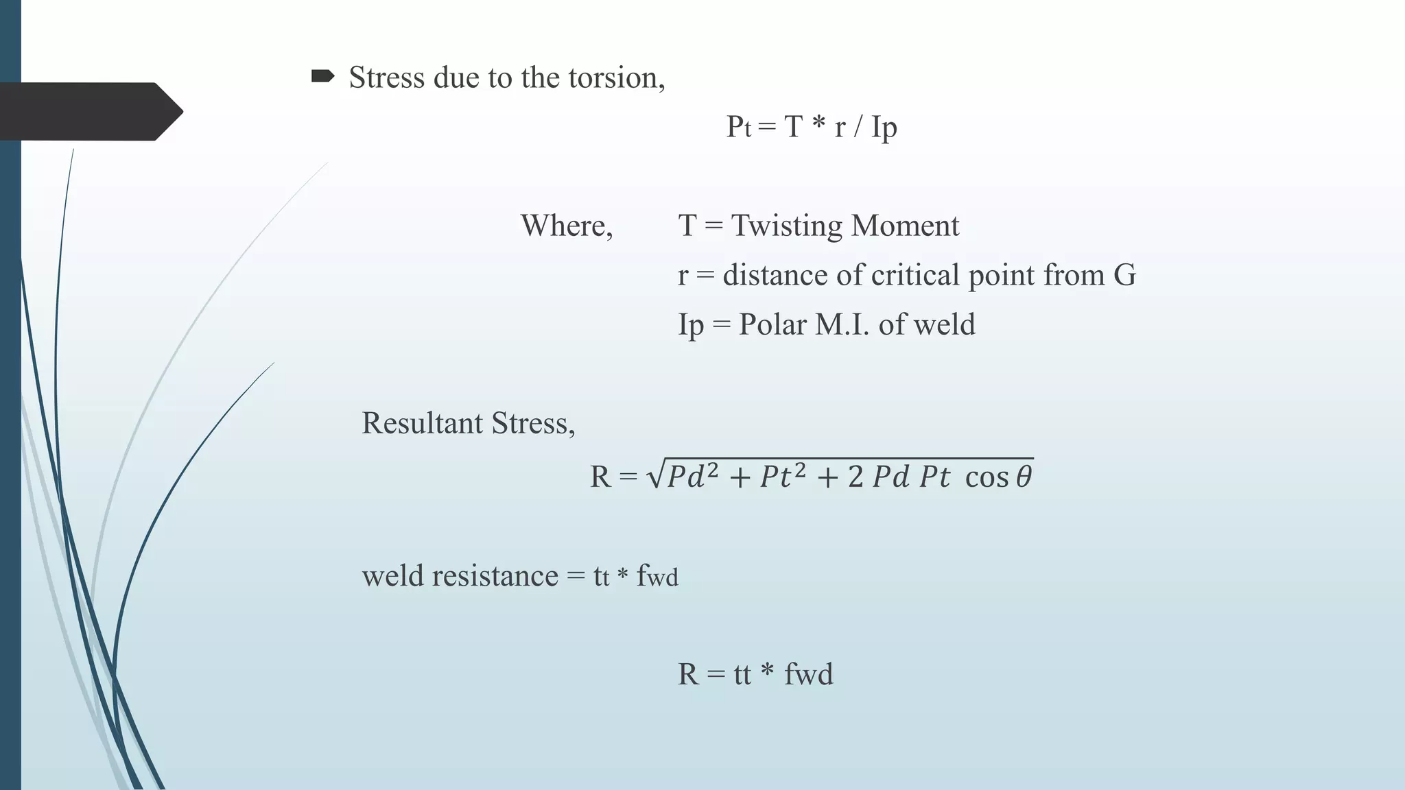
Stress dueto the torsion,
Pt = T * r / Ip
Where, T = Twisting Moment
r = distance of critical point from G
Ip = Polar M.I. of weld
Resultant Stress,
R = 𝑃𝑑2 + 𝑃𝑡2 + 2 𝑃𝑑 𝑃𝑡 cos 𝜃
weld resistance = tt * fwd
R = tt * fwd
10.
(a) Eccentric LoadCausing Bending Moment
The centre of gravity of the weld does not lies in the plane of line of action
of the applied load.
The load will cause direct shear and bending moment in the weld.
11.
1. Fillet Welds:
•Direct Shear Stress = Load / Effective area of the weld
Q = P / 2 * lw *tt
• Bending Stress = Moment / Section Modulus
fa = M / Z = M / I * y
• Resultant Stress,
𝑓𝑎2 + 𝑞2
12.
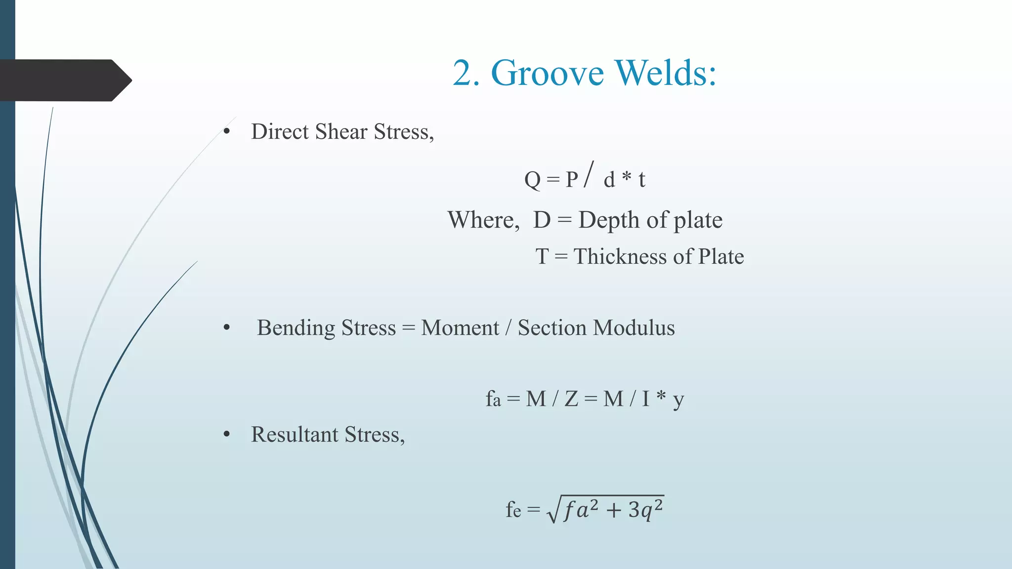
2. Groove Welds:
•Direct Shear Stress,
Q = P / d * t
Where, D = Depth of plate
T = Thickness of Plate
• Bending Stress = Moment / Section Modulus
fa = M / Z = M / I * y
• Resultant Stress,
fe = 𝑓𝑎2 + 3𝑞2
13.
Examples
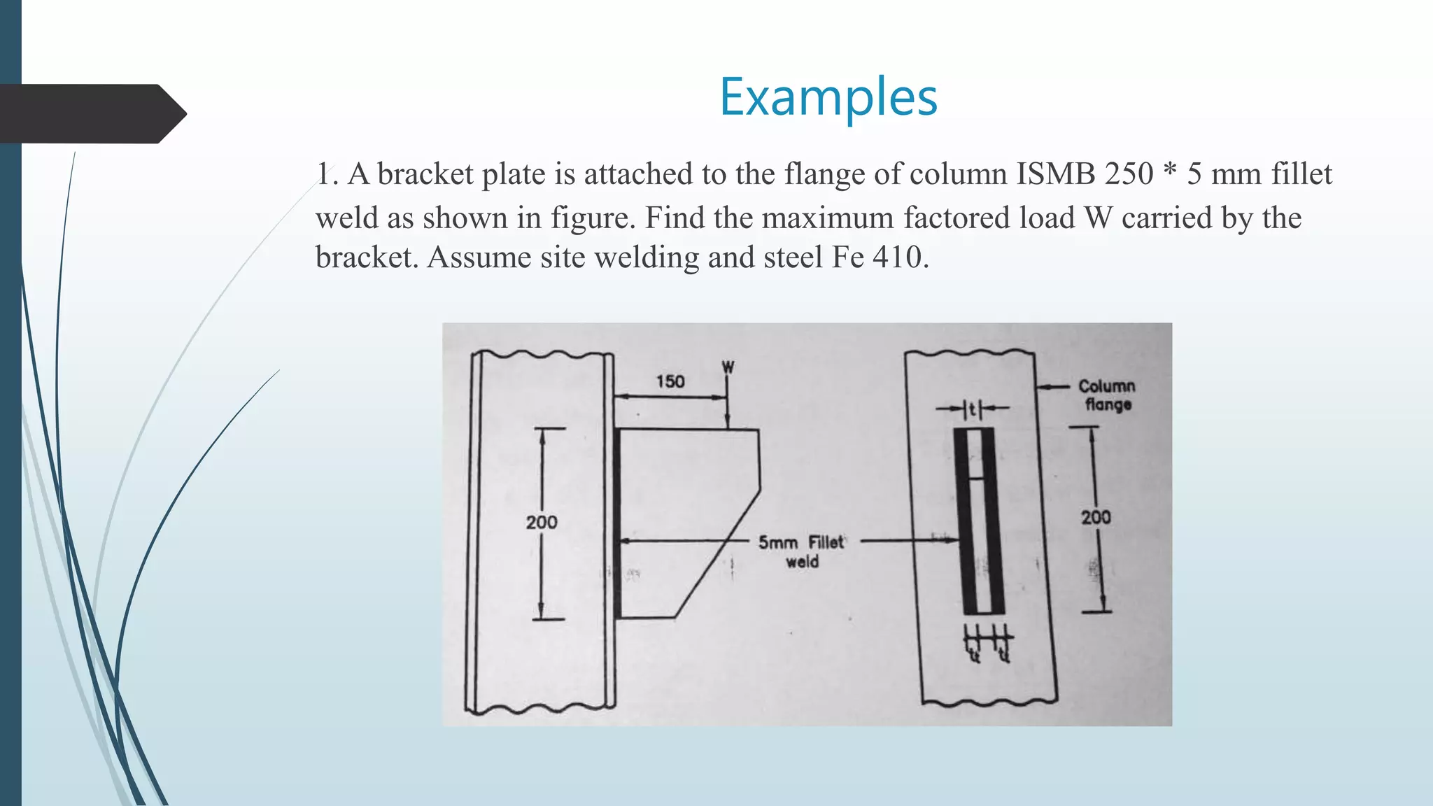
1. A bracketplate is attached to the flange of column ISMB 250 * 5 mm fillet
weld as shown in figure. Find the maximum factored load W carried by the
bracket. Assume site welding and steel Fe 410.
14.
The loadwill cause direct shear and tension due to bending.
Assume throat thickness equal to unity.
Direct shear stress = Load / Effective area of weld
q = W / (200 * 2* 1)
= 2.5 * 10−3
W N/mm
Moment = M = W * 150 N/mm
Izz = 2 * 1*(200³ / 12)
= 1.33 * 106
𝑚𝑚4
y = 200 / 2
= 100 mm
Bending Stress = M * y / I
= W * 150 * 100 / 1.33 * 106
= 0.0113 W N/mm
15.
Vector sumof stress,
fe = 𝑓𝑎2 + 𝑞2
= (0.0113 𝑊 )2 + ( 2.5 ∗ 10−3 𝑊)2
= 0.0115 W N/mm
Strength of 5 mm fillet weld
= tt * fwd
= 0.70 * 5 * 158 (fwd = 158 N/𝑚𝑚2 for the field weld)
= 553 N/mm
Now,
0.0115 W = 553
W = 48086 N
W = 48.086 kN
16.
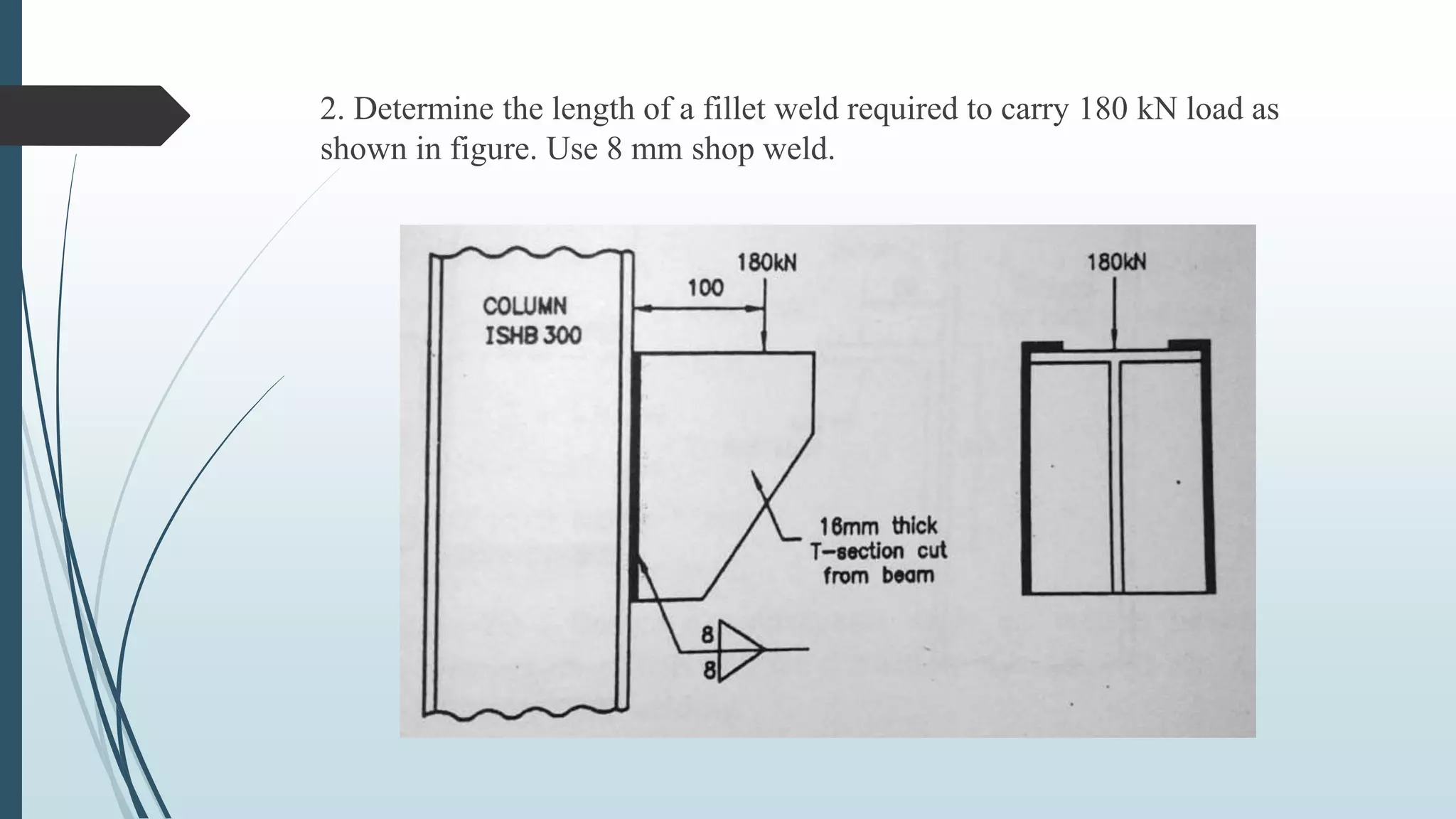
2. Determine thelength of a fillet weld required to carry 180 kN load as
shown in figure. Use 8 mm shop weld.
17.
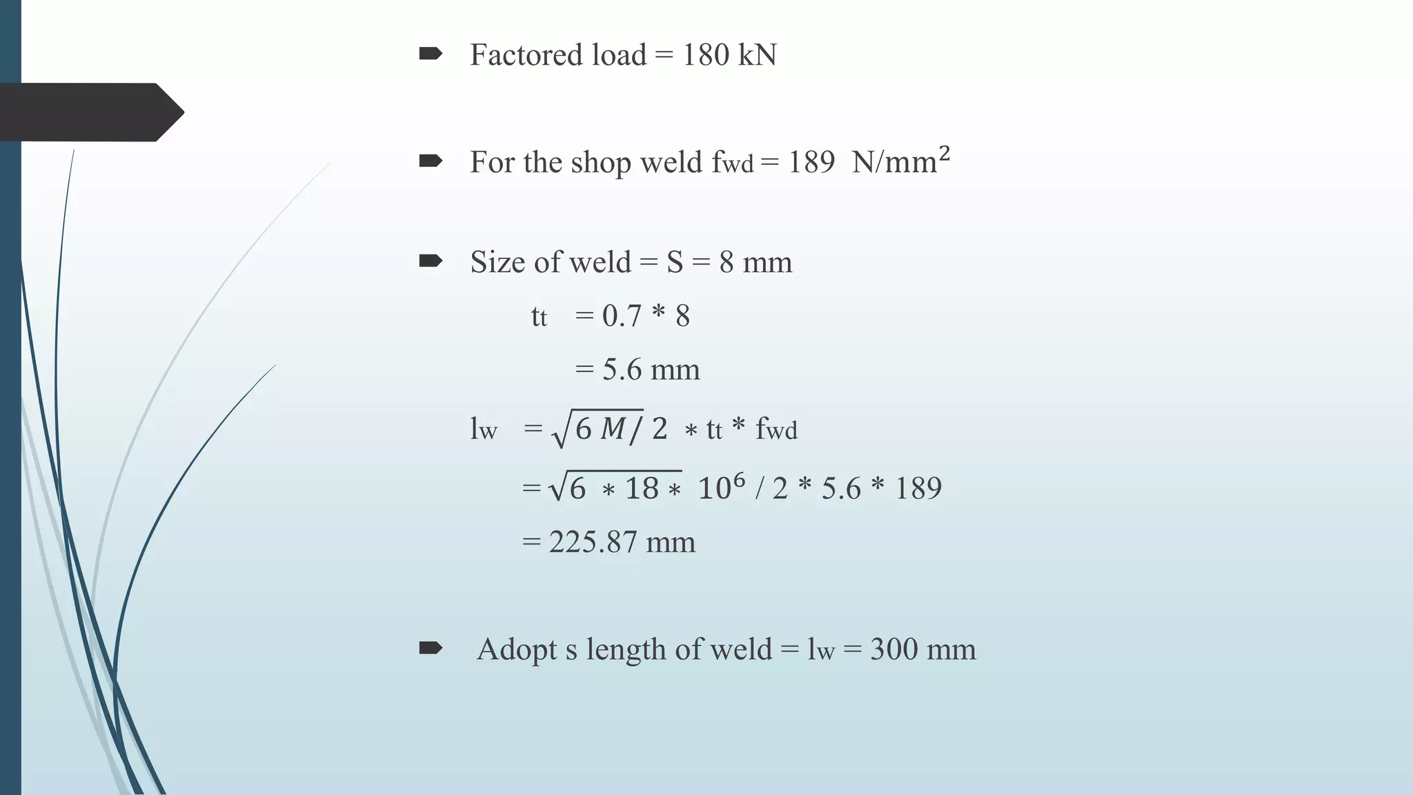
Factored load= 180 kN
For the shop weld fwd = 189 N/mm2
Size of weld = S = 8 mm
tt = 0.7 * 8
= 5.6 mm
lw = 6 𝑀/ 2 ∗ tt * fwd
= 6 ∗ 18 ∗ 106 / 2 * 5.6 * 189
= 225.87 mm
Adopt s length of weld = lw = 300 mm
18.
Direct ShearStress,
q = P / (2 * lw * tt )
= 180 * 103 / (2 * 300 * 5.6)
= 53.53 N / 𝑚𝑚2
Bending Stress,
fb = 6M / (2 * lw * tt )
= (6 * 18 * 106
) / (2 * 5.6 * 3002
)
= 107.14 N / 𝑚𝑚2
Resultant Stress,
fe = 𝑓𝑏2 + 𝑞2
= (114.28 )2 + (47.62)2
= 123.80 N / 𝑚𝑚2
< 189 N / 𝑚𝑚2
therefore O.K.
Hence, 300 mm length of fillet weld is used 8 mm is sufficient.