Download to read offline


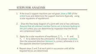
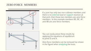
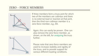
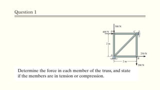
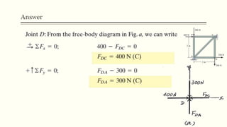
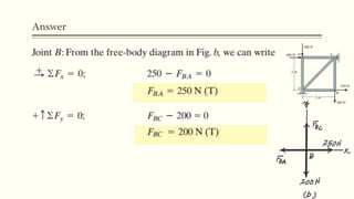
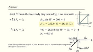
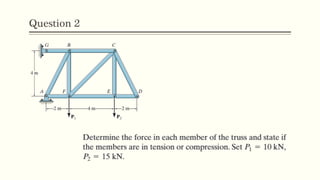
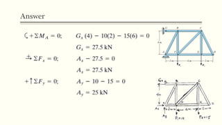
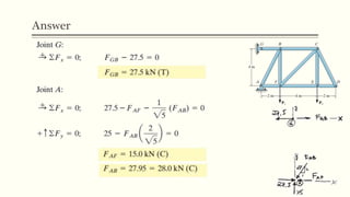
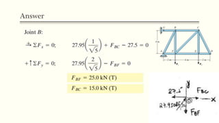
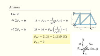
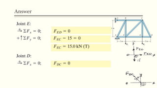
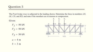
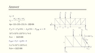
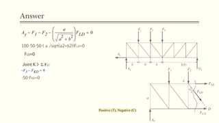
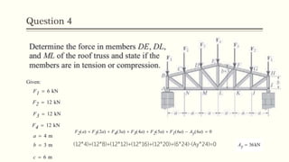
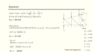

The document provides instructions for analyzing truss structures. It outlines 4 steps: 1) determine support reactions if not given, 2) draw free body diagrams of joints with unknown forces, 3) apply equilibrium equations to solve for unknowns, 4) repeat steps 2 and 3 until all forces are determined. It also discusses zero-force members, which can be removed from the truss for analysis if they meet certain criteria. Zero-force members do not carry loads but increase stability. The document contains sample problems and solutions demonstrating these concepts.


