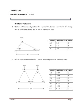
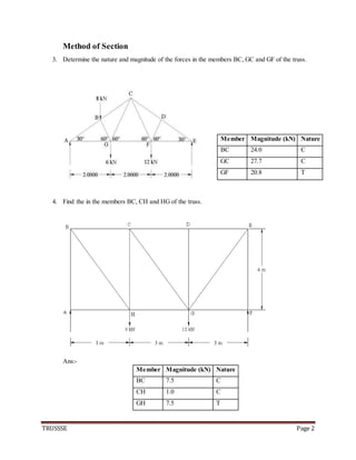
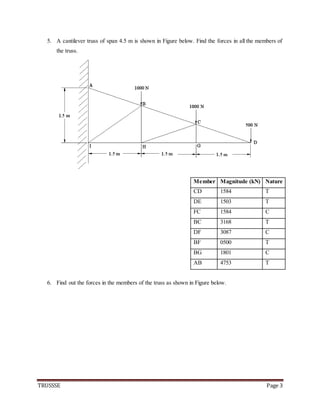
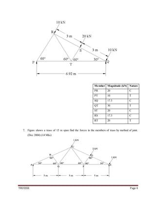
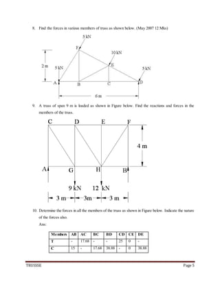
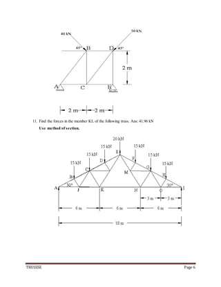
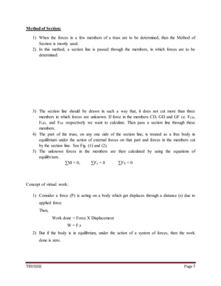
Coefficient of Thermal Expansion and their Importance.pptx
Truss problems
1. TRUSSSE Page 1
CHAPTER NO.4
ANALYSIS OF PERFECT TRUSSES
By Method of Joint:
1. The truss ABC shown in Figure below has a span of 5 m. it carries a load of at 10 kN at its top.
Find the forces in the member AB, BC and AC. (Method of Joint)
2. Find the forces in all the members of a truss as shown in Figure below. (Method of Joint)
Member Magnitude (kN) Nature
AB 8.66 C
BC 4.33 T
AC 5.00 C
Member Magnitude (kN) Nature
AB 2.887 C
AE 1.444 T
CD 4.042 C
DE 2.021 T
BE 0.577 T
BC 1.732 C
CE 0.577 C
2. TRUSSSE Page 2
Method of Section
3. Determine the nature and magnitude of the forces in the members BC, GC and GF of the truss.
4. Find the in the members BC, CH and HG of the truss.
Ans:-
Member Magnitude (kN) Nature
BC 24.0 C
GC 27.7 C
GF 20.8 T
Member Magnitude (kN) Nature
BC 7.5 C
CH 1.0 C
GH 7.5 T
3. TRUSSSE Page 3
5. A cantilever truss of span 4.5 m is shown in Figure below. Find the forces in all the members of
the truss.
Member Magnitude (kN) Nature
CD 1584 T
DE 1503 T
FC 1584 C
BC 3168 T
DF 3087 C
BF 0500 T
BG 1801 C
AB 4753 T
6. Find out the forces in the members of the truss as shown in Figure below.
4. TRUSSSE Page 4
Member Magnitude (kN) Nature
PR 20 C
PT 10 T
SQ 17.3 C
QT 30 T
ST 20 C
RS 17.3 C
RT 20 T
7. Figure shows a truss of 15 m span find the forces in the members of truss by method of joint.
(Dec 2004) (14 Mks)
5. TRUSSSE Page 5
8. Find the forces in various members of truss as shown below. (May 2007 12 Mks)
9. A truss of span 9 m is loaded as shown in Figure below. Find the reactions and forces in the
members of the truss.
10. Determine the forces in all the members of the truss as shown in Figure below. Indicate the nature
of the forces also.
Ans:
Members AB AC BC BD CD CE DE
T - 17.68 - - 25 0 -
C 15 - 17.68 38.88 - 0 38.88
6. TRUSSSE Page 6
11. Find the forces in the member KL of the following truss. Ans: 41.96 kN
Use method of section.
7. TRUSSSE Page 7
Method of Section:
1) When the forces in a few members of a truss are to be determined, then the Method of
Section is mostly used.
2) In this method, a section line is passed through the members, in which forces are to be
determined.
3) The section line should be drawn in such a way that, it does not cut more than three
members in which forces are unknown. If force in the members CD, GD and GF i.e. FCD,
FGD, and FGF respectively we want to calculate. Then pass a section line through these
members.
4) The part of the truss, on any one side of the section line, is treated as a free body in
equilibrium under the action of external forces on that part and forces in the members cut
by the section line. See Fig. (1) and (2).
5) The unknown forces in the members are then calculated by using the equations of
equilibrium.
∑M = 0, ∑Fy = 0 ∑FX = 0
Concept of virtual work:
1) Consider a force (P) is acting on a body which get displaces through a distance (s) due to
applied force.
Then,
Work done = Force X Displacement
W = F.s
2) But if the body is in equilibrium, under the action of a system of forces, then the work
done is zero.
8. TRUSSSE Page 8
3) If we assume that the body, which is in equilibrium, undergoes a small imaginary
displacement (virtual displacement) some work will be imagined to be done. Such
imaginary work is called as virtual work. This concept is useful to find out the unknown
forces in the structures.
Principle of virtual work:
“ If system of forces acting on a body (or a system of bodies) be in equilibrium and the
system to be imagined to undergo a small displacement consistent with the geometrical
conditions, then the algebraic sum of the virtual works done by all the system is zero”.
i.e. mathematically,
∑W = 0
Types of virtual work:
1) Linear virtual work:
If a force (F) causes a displacement (virtual displacement) in its direction of line of
action, then its virtual work is given as,
WV = F x δ
Sign convention:
Upward forces are considered as positive, while downward forces are considered as
negative