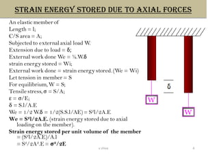
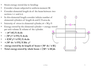
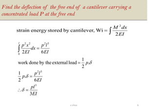
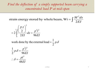
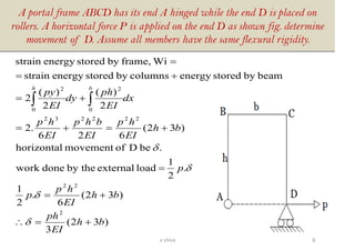
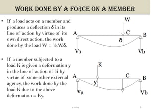
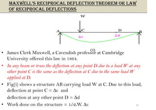
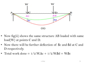
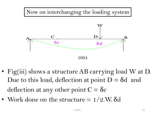
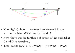
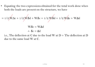
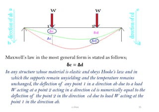
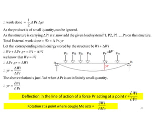
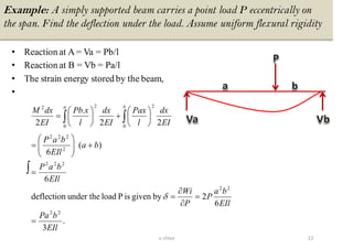
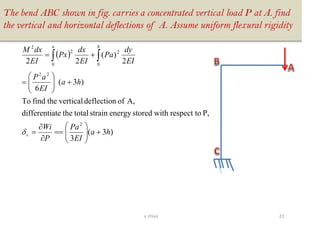
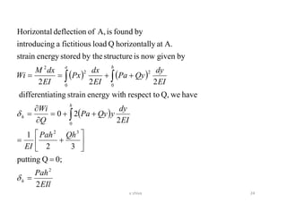
1v shiva
• Concept of strain energy
• Strain energy stored due to axial forces
• Strain energy stored due to bending stresses.
• Maxwell’s reciprocal deflection theorem or law of reciprocal
deflections
• Betti’s law
• Castigliano’s theorem-I
• Castigliano’s theorem-II
• Unit load method.
• Analysis of trusses having redundancy 1 and more than 1
• Lack of fit in indeterminate frames
• Temperature stresses in redundant frames
2v shiva
STRAIN ENERGY
• When an elastic member is deformed under the action
of an external loading the member is said to have
possessed or stored energy which is called the strain
energy of the member or the resilience of the member.
• Strain energy stored by a member = work done by the
external forces to produce deformation.
• If the elastic limit is not exceeded the external work
is transformed into elastic strain energy, which is
recoverable as member returns to its original
condition as the load is removed.
3v shiva
STRAIN ENERGY STORED DUE TO AXIAL forces
An elastic member of
Length = l;
C/S area = A;
Subjected to external axial load W.
Extension due to load = δ;
External work done We = ½.W.δ
strain energy stored = Wi;
External work done = strain energy stored. (We = Wi)
Let tension in member = S
For equilibrium,W = S;
Tensile stress, σ = S/A;
ε = σ/E;
δ = S.l/A.E
We = 1/2 W.δ = 1/2(S.S.l/AE)= S2l/2A.E
We = S2l/2A.E. (strain energy stored due to axial
loading on the member).
Strain energy stored per unit volume of the member
= (S2l/2A.E)/A.l
= S2/2A2.E = σ2/2E
4v shiva
• Strain energy stored due to bending:
• Consider a beam subjected to uniform moment M.
• Consider elemental length ds of the beam between two
sections 1-1 and 2-2.
• In this elemental length consider infinite number of
elemental cylinders of length ds and C/S area da.
• Intensity of stress in elemental cylinder, σ = M.y/I
• Energy stored by the elemental cylinder = energy stored
per unit volume X volume of the cylinder.
• = (σ2/2E) X ds.da
• = (M2 y2/2 I2E) X ds.da
• = Σ(M2 y2/2 I2E) X ds.da
• = (M2 ds / 2 I2E) X Σda .y2
• energy stored by ds length of beam = (M2 ds / 2 IE)
• Total energy stored by whole beam = ∫(M2 / 2 IE)ds
5v shiva
Find the deflection of the free end of a cantilever carrying a
concentrated load P at the free end
EI
pl
EI
lp
p
p
EI
lp
dx
EI
xp
l
3
6
.
2
1
.
2
1
loadexternalby thedonework
62
3
32
32
0
22
=
=
=
=



=
EI
dxM
2
Wi,cantileverbystoredenergystrain
2
6v shiva
Find the deflection of a simply supported beam carrying a
concentrated load P at mid-span
EI
pl
EI
lp
p
p
EI
lp
dx
EI
xp
l
48
96
.
2
1
.
2
1
loadexternalby thedonework
962
2
.
2
3
32
322/
0
2
=
=
=
=






= 



=
EI
dxM
2
Wibeam,by wholestoredenergystrain
2
7v shiva
A portal frame ABCD has its end A hinged while the end D is placed on
rollers. A horizontal force P is applied on the end D as shown fig. determine
movement of D. Assume all members have the same flexural rigidity.
)32(
3
)32(
6
.
2
1
.
2
1
loadexternalby thedonework
.beDofmovementhorizontal
)32(
626
.2
2
)(
2
)(
2
beambystoredenergycolumnsbystoredenergystrain
Wiframe,bystoredenergystrain
2
22
222232
0
2
0
2
bh
EI
ph
bh
EI
hp
p
p
bh
EI
hp
EI
bhp
EI
hp
dx
EI
ph
dy
EI
py
bh
+=
+=
=
+=+=
+=
+=
=





8v shiva
Work done by a force on a member
• If a load acts on a member and
produces a deflection δ in its
line of action by virtue of its
own direct action, the work
done by the load W = ½.W.δ.
• If a member subjected to a
load K is given a deformation y
in the line of action of K by
virtue of some other external
agency, the work done by the
load K due to the above
deformation = Ky.
9v shiva
MAXWELL’S RECIPROCAL DEFLECTION THEOREM OR LAW
OF RECIPROCAL DEFLECTIONS
• James Clerk Maxwell, a Cavendish professor at Cambridge
University offered this law in 1864.
• In any beam or truss the deflection at any point D due to a load W at any
other point C is the same as the deflection at C due to the same load W
applied at D.
• Fig(i) shows a structure AB carrying load W at C. Due to this load,
deflection at point C = ∆c and
deflection at any other point D = ∆d
• Work done on the structure = 1/2.W. ∆c 10v shiva
• Now fig(ii) shows the same structure AB loaded with same
load(W) at points C and D.
• Now there will be further deflection of δc and δd at C and
D respectively.
• Total work done = 1/2.W.∆c + 1/2.W.δd + W.δc
11v shiva
• Fig(iii) shows a structure AB carrying load W at D.
Due to this load, deflection at point D = δd and
deflection at any other point C = δc
• Work done on the structure = 1/2.W. δd
12v shiva
• Now fig(iv) shows the same structure AB loaded
with same load(W) at points C and D.
• Now there will be further deflection of ∆c and ∆d at
C and D respectively.
• Total work done = 1/2.W.δd + 1/2.W.∆c + W.∆d
13v shiva
• Equating the two expressions obtained for the total work done when
both the loads are present on the structure, we have
= 1/2.W.∆c + 1/2.W.δd + W.δc = 1/2.W.δd + 1/2.W.∆c + W.∆d
W.δc = W.∆d
∴ δc = ∆d
i.e., The deflection at C due to the load W at D = The deflection at D
due to the same load W at C.
14v shiva
Maxwell’s law in the most general form is stated as follows;
δc = ∆d
In any structure whose material is elastic and obeys Hooke’s law and in
which the supports remain unyielding and the temperature remains
unchanged, the deflection of any point 1 in a direction ab due to a load
W acting at a point 2 acting in a direction cd is numerically equal to the
deflection of the point 2 in the direction cd due to load W acting at the
point 1 in the direction ab.
15v shiva
BETTI’S LAW
This is generalized form of Maxwell’s law offered by
Italian professor, E.Betti in 1872. The law is stated as
follows:
In any structure whose material is elastic and obeys Hooke’s
law and in which the supports remain unyielding and the
temperature remains constant, the virtual work done by a
system of forces P1, P2, P3 …. during the distortion caused
by a system of forces Q1, Q2, Q3 … is equal to the virtual
work done by the system of forces Q1, Q2, Q3 …during the
distortion caused by the system of forces, P1, P2, P3 …
16v shiva
In any structure whose materialis elastic
and obeys Hooke’s law and in which the
supports remain unyielding and the
temperatureremains constant, the virtual
work done by a system of forces P1, P2, P3
…. during the distortion caused by a system
of forces Q1, Q2, Q3 … is equal to the
virtual work done by the system of forces
Q1, Q2, Q3 …during the distortion caused
by the system of forces, P1, P2, P3 …
P1y1 + P2y2 + P3y3 = Q1Y1 + Q2Y2
+ Q3Y3
17v shiva
THE FIRST THEOREM OF CASTIGLIANO
• The first theorem of Castigliano states that the
partial derivative of total strain energy in any
structure with respect to the applied force or
moment gives the displacement or rotation
respectively at the point of application of force or
moment in the direction of applied force or
moment.
18v shiva
• Let the deflection at r be yr.
• We = external work done by the given load system.
• Wi = correspondingstrain energy stored.
∴We = Wi
Let ∆Pr aloneis applied getting
deformation of ∆yr.
19v shiva
Pr
quantity.smallinfinitelyanisPrwhenjustifiedisrelationaboveThe
Pr
.Pr
thatknowwe
.Pr
bestructureby thestoredenergystrainingcorrespondLet the
.PrdoneworkExternalTotal
structure.on the....PnP3,P2,P1,systemloadgiventheaddnowr,atPrcarryingisstructuretheAs
ignored.becanquantity,smallofisproducttheAs
.Pr.
2
1
donework


=



=
=
=
+=+
+
+=

=
Wi
yr
Wi
yr
Wiyr
WiWe
WiWiyrWe
WiWi
yrWe
yr
Pr
Wi
Rotationat a point where couple Mo acts =
Mo
Wi


20v shiva
• In case the deflection is to be determined at a point
where no load acts introduce a fictitious force Q at
the point in the direction of the desired deflection.
The partial derivative of strain energy stored
with respect to Q is determined, and Q is put equal
to zero.
21v shiva
Example: A simply supported beam carries a point load P eccentrically on
the span. Find the deflection under the load. Assume uniform flexural rigidity
• Reaction at A = Va = Pb/l
• Reaction at B = Vb = Pa/l
• The strain energy stored by the beam,
•


=
=


=
=
+





=






+





=
.
3
6
2bygivenisPloadunder thedeflection
6
)(
6
22
.
2
22
22
222
2
222
0
2
0
22
EIl
bPa
EIl
ba
P
P
Wi
EIl
baP
ba
EIl
baP
EI
dx
l
Pax
EI
dx
l
xPb
EI
dxM
ba

22v shiva
The bend ABC shown in fig. carries a concentrated vertical load P at A. find
the vertical and horizontal deflections of A. Assume uniform flexural rigidity
( )
)3(
3
P,respect towithstoredenergystraintotaltheatedifferenti
A,ofdeflectionverticalthefindTo
)3(
6
2
)(
22
2
22
0
2
0
2
2
ha
EI
Pa
P
Wi
ha
EI
aP
EI
dy
Pa
EI
dx
Px
EI
dxM
v
ha
+





==


=
+





=
+= 

23v shiva
( ) ( )
( )
EIl
Pah
QhPah
EI
EI
dy
yQyPa
Q
Wi
EI
dy
QyPa
EI
dx
Px
EI
dxM
Wi
h
h
h
ha
2
0;Qputting
32
1
2
20
haveweQ,respect tohenergy witstrainatingdifferenti
222
bygivennowisstructureby thestoredenergystrain
A.atlyhorizontalQloadfictitiousagintroducin
byfoundisA,ofdeflectionHorizontal
2
32
0
0
2
0
2
2
=
=






+=
++=


=
++==




24v shiva
THE SECOND THEOREM OF CASTIGLIANO
The second theorem of castigliano states that the work done by
external forces in a structure will be minimum. The theorem is
very useful in analysis of indeterminate structures.
Let W be the work done by the external forces on the structure, U be
the strain energy stored in the structure and W1 be the work done
by the reactive forces.
Strain energy U = W + W1
W = U – W1
By castigliano’s second theorem W should be minimum. Thus the
partial derivative of the work done with respect to external
forces will be zero.
In case the supports are unyielding the work done by reactive forces
will be zero. Strain energy stored will be equal to the work done by
external forces and will be the minimum. Thus the partial
derivative of strain energy with respect to redundant reaction will
be zero.
25v shiva
EI
lw
EI
xwxxQ
deflection
EI
dxwxxQ
EI
dxM
l
l
8
.
endfreeatDeflection
integrate;and0Qput
2
).2/.(2
Q,w.r.tatingdifferentiso,
Q
Wi
rem,first theoso'castigliantoAccording
2
)2/.(
2
Q,loadfictituousaintroduce
end,freeatdeflectionthefindTo
4
0
2
0
222
=
=
+
=
=


+
=


26v shiva
To find the reaction at the free end of propped cantilever carrying
UDL using Castigliano’s second theorem
8
3
83
0
83
1
0
2
).2/.(2
zero,toequatingandQw.r.tatingdifferentiso,
0
Q
Wi
minimum,betodeflectionfor thetheoremsecondso'castigliantoAccording
2
)2/.(
2
Q,loadfictituousaintroduce
end,freeatdeflectionthefindTo
43
43
0
2
0
222
wl
Q
wlQl
wlQl
EI
EI
xwxxQ
EI
dxwxxQ
EI
dxM
l
l
=
==
=





−=
=
−
=
=


−
=


27v shiva
Find the vertical reaction at C for the frame shown in figure
( )
( )
( )
13
4
0
12448
0
2
.
22
.
..
)2(
0
22
.
22
.
.2.
)2(2
2
R
Wi
;0
R
Wi
i.e.,minimum,is
storedenergystrainthatconditionfromobtainedbecanR
222
.
)2(22
columninstoredenergystrainbeaminstoredenergystrain
frameby thestoredenergyStrain
433
0
22/
0
2
0
22/
0
0
222/
0
2
2
WL
R
WLRL
EI
RL
EI
dyLwyLR
IE
dx
Rx
EI
dyLwyLR
x
IE
dx
Rx
EI
dywyLR
IE
dx
Rx
EI
dxM
wi
ll
ll
ll
=
=−+=
=





−+=
=





−+=


=








−+==
+=



28v shiva
lx
xwL
wx
clockwiseanti
wL
Ma
wL
clockwiseanti
lefttowardswL
upwardswL
downwardswL
445.0
0.
226
9wL
at,occursurecontraflexofpoint
)(
26
9
0
213
2wL
MaAatMoment
)(
13
2wL
2
L
wL.
13
4
BatMoment
)(Aatreactionhorizontal
)(
13
4
Catreaction
)(
13
4
Aatreaction
22
2
22
2
=
=+−=
−=
=−+=
−==
=
=
=
29v shiva
REDUNDANT TRUSSES
30v shiva







=
=
=
+
=



=


+
=
==
1.1
P1.K1.L1
Xhavewe
thenmembers,allforsameisEandareassectional-crosstheIf
.1
1.1
.1
1.1.1
;0
2
1.1)1.1(2
X
Wi
0
X
Wi
i.e.,
minimum,isstoredenergystrainconditionby theobtainedbecanX
2
1)1.1(
2
11
frameby thestoredenergystrainTotal
2
2
1
1
2
1
2
LK
EA
LK
EA
LKP
X
EA
LKKXP
EA
LKXP
Wi
EA
LS
Wi
31v shiva
steps to analyze the redundant frame
Step-I: consider a member(say BC) as redundant and remove BC and find
member forces P1,P2,P3,.. For the given loading system.
Step-II: Remove the given loading systemand apply a pair of unit forces at B
and C. find the member forces K1,K2,K3,..
Step-III: Tabulate the above results as follows:
Step-IV: find a correcting factor X given by
member P K L A PKL/A K2 L/A
TOTAL Σ(PKL/A) Σ(K2 L/A)


=
A
LK
A
LKP
X
.
..
2
32v shiva
Step-V: Now find the force in any member by the relation
S = P + X.K
33v shiva
Example: Determine the forces in the members of the frame shown in
fig. sectional areas in millimeters
• Solution: Let BD is redundant, so remove
BD and find forces.
If we resolve and solve we get
force in members as;
Pca = 15√41KN(compressive)
Pcd = 60KN(Tensile)
Pda = 75KN(Tensile)
Pcb = 0
Pba = 0
34v shiva
• Now remove the given load and apply a pair of unit loads at B
and D in place of member BD.
Kdc = 4/√41(compressive)
Kda = 5/√41(compressive)
Kcb = 5/√41(compressive)
Kba = 4/√41(compressive)
Kca = 1(Tensile)
The actual force in the
member is given by
S = P + X.K,


=
A
LK
A
LKP
X
.
..
2
35v shiva
member P K L A PKL/A K2 L/A
AB 0 4/√41 4000 900 0 1.7344
BC 0 5/√41 5000 1200 0 2.5407
CD -60 4/√41 4000 900 -166.585 1.7344
DA -75 5/√41 5000 1200 -244.022 2.5407
AC 15√41 -1 1000√41 1500 -410 4.2687
BD 0 -1 1000√41 1500 0 4.2687
TOTAL -820.607 17.0876
36v shiva
• X = 820.607/17.0876
∴The actual force in the members are calculated as below;
• Sab = Pab + X.Kab = 0 + 48.0235X4/√41 = 30KN(compressive)
• Sbc = Pbc + X.Kbc = 0 + 48.0235X5/√41 = 37.5KN(compressive)
• Scd = Pcd + X.Kcd = -60 + 48.0235X4/√41 = -30KN (tensile)
• Sda = Pda + X.Kda = -75 + 48.0235X5/√41 = -37.5KN(tensile)
• Sac = Pac + X.Kac = 48.0235(-1)+15√41 =
48.023KN(compressive)
• Sbd = Pbd + X.Kbd = 0 + 48.0235(-1)= -48.023KN(tensile)
37v shiva
Frame with two redundant members
• Fig.1 shows a truss with two redundant members.
• Let S1,S2,S3,… be the actual forces.
• Let BF and DF be the redundant members.
• Let P1,P2,P3,..be the member forces after removing
BF and DF shown in fig.2.
• Let the member forces be K1,K2,K3,..due to unit load
at B and F as shown in fig.3
• Let the member forces be K’1,K’2,K’3,..due to unit load
at D and F as shown in fig.4
• The actual forces in the members of the truss are
given by,
• S1=P1+XK1+YK’1;
• S2=P2+XK2+YK’3; and so on…
38v shiva
(ii)and(i)equationssolvingbydeterminedbecanYandXunknownsThe
).....(0
1
11'1
1
11'
1
11'1
0
12
11')1'11(2
Y
Wi
,
)......(0
1
11'1
1
11
1
111
0
12
11)1'11(2
X
Wi
0
Wi
;0
X
Wi
conditionsby thei.e.,minimum,isstoredenergystrainthat the
conditionby thegivenareYandXquantitiesredundantThe
12
1)1'11(
12
11
trussby thestoredenergystrainThe
2
2
2
2
ii
EA
LKK
Y
EA
LK
X
EA
LKP
EA
LKYKXKP
similarly
i
EA
LKK
Y
EA
LK
X
EA
LKP
EA
LKYKXKP
Y
EA
LYKXKP
Wi
EA
LS
Wi
=++
=
++
=


=++
=
++
=


=


=


++
=
==






39v shiva
Find the forces in the members FD and DH of the frame shown in
figure. The ratio of length to the cross-sectional area for all the
members is the same
• Given l/A is constant for all members.
• Consider FD and DH to be redundant members and assume them
to be removed.
• Let,
• X = Force in member FD
• Y = force in member DH
40v shiva
41v shiva
42v shiva
P K K’ PK PK' K
2
K
’2
KK’
AC -42.42 0 0 0 0 0 0 0
CD -60 -0.707 0 42.42 0 0.5 0 0
DE -60 0 -0.707 0 42.42 0 0.5 0
EB -70.71 0 0 0 0 0 0 0
AF 30 0 0 0 0 0 0 0
FG 30 -0.707 0 -21.21 0 0.5 0 0
GH 50 0 -0.707 0 -35.35 0 0.5 0
HB 50 0 0 0 0 0 0 0
CF 0 -0.707 0 0 0 0.5 0 0
CG 42.42 1 0 42.42 0 1 0 0
DG 0 -0.707 -0.707 0 0 0.5 0.5 0.5
EG 14.14 0 1 0 14.14 0 1 0
EH 40 0 -0.707 0 -28.28 0 0.5 0
DF 0 1 0 0 0 1 0 0
DH 0 0 1 0 0 0 1 0
TOTAL 63.63 -7.07 3.999 3.999 0.5
43v shiva
)(81.3
)(38.16
(ii)and(i)equationssolving
).......(05.0407.7
.0
'''
).....(05.0463.63
.0
'
2
2
tensionY
ncompressioX
iiXY
AE
LKK
X
AE
LK
Y
AE
LPK
iYX
AE
LKK
Y
AE
LK
X
AE
PKL
=
−=
=++−
=++
=++
=++


44v shiva
)(81.3)1)(81.3()0)(38.16(0
)(380.16)0)(81.3()1)(38.16(0
)(306.37)707.0)(81.3()0)(38.16(40
)(95.17)1)(81.3()0)(38.16(14.14
)(887.8)707.0)(81.3()707.0)(38.16(0
)(04.26)0)(81.3()1)(38.16(42.42
)(581.11)0)(81.3()707.0)(38.16(0
)(50)0)(81.3()0)(38.16(50
)(306.47)707.0)(81.3()0)(38.16(50
)(58.41)0)(81.3()707.0)(38.16(30
)(30)0)(81.3()0)(38.16(30
)(71.70)707.0)(81.3()0)(38.16(71.70
)(69.62)0)(81.3()0)(38.16(60
)(41.48)0)(81.3()707.0)(38.16(60
,
)(42.42)0)(81.3()0)(38.16(42.42
')81.3()38.16(
ncompressioSdh
tensionSdf
ncompressioSeh
ncompressioSeg
ncompressioSdg
ncompressioScg
ncompressioScf
ncompressioShb
ncompressioSgh
ncompressioSfg
ncompressioSaf
tensionSeb
tensionSde
tensionScd
similarly
tensionSac
acKKacPacSac
+=++−=
−=++−=
+=−+−+=
+=++−+=
+=−+−−=
+=++−+=
+=+−−=
+=+−+=
+=−+−+=
+=+−−+=
+=+−+=
−=−+−−=
−=+−−=
−=+−−−=
−=+−−=
+−+=
45v shiva
46v shiva
member P K K’ L PKL PK’L K2L K’2L KK’L
TOTAL -25.25 -36 8.44 8.64 0.636
47v shiva
48v shiva
figure:2
49v shiva
LACK OF FIT:
• Lack of fit is an occurance in trussesin which there is a differencebetween the
lengthof a member and the distance between the nodes it is supposedto fit.
• This happens because the connecting member is either too long or too short as
compared to the distance between corresponding nodes.
• It must also be noted here that lack of fit occurs only in indeterminate trusses because in
determinate trusses the variation in member length automatically adjusts the spacing
between the nodes, hence, lack of fit cannot occur.
• A lack of fit may be unintentionally introduced in a truss due to fabrication errors or it
may be deliberately introduced as a part of the design by the engineer.
• In cases of lack of fit, the member is either forcibly lengthened or forcibly shortened to
fit the truss depending on whether it is too short or too long respectively. This causes
the various members meeting at these joints to develop stresses of opposite nature. This
pre-stress occurring due to lack of fit may be used advantageously in design of truss.
• The members that develop tension due to loading may be introduced with a
compressive pre-stress and the members that develop compression may be introduced
with a tensile pre-stress. This effectively increases the stress range over which a
member may be loaded and the maximum load carrying capacity of the truss.
50v shiva
Consider a statically indeterminateframe in which
one of the members BC is shorterthan its length
by amount δ.
To fit this member in position, the joints will have to
be brought closer and member itself will get
elongated and thus will be in tension.
Let ‘x’ be the force in the member having lack of fit
To analyze the frame, it is made determinateby
removing the member having lack of fit
Unit forces are applied at the joints of the members
having lack of fit as shown in fig
• Let ‘k’ be the force in the member due to
unit forces.
• The force in the member due to force ‘x’will be
‘kx’.
• The strain energy in all the members of
determinateframe will be
51v shiva
( )





+
=
=+
=+
=
=


=
AoE
l
AE
lK
X
EA
Xl
AE
lK
X
EA
Xl
AE
lXK
AE
lXK
X
U
AE
lKX
U
O
O
O
o
o
o
2
2
o
2
2
2
.
.
fit.oflackhavingmembertheof
ly,respectiveareaandlengthareAandlwhere
.
.
forceofdirectioninmovement
2




52v shiva


+
−=
+
=
AoE
l
AE
lK
X
AoE
l
AE
lK
X
O
O
2
2
tensile.belmember wilin theforceshort,tooismembertheIf
e,compressivbelmember wilin theforcelong,tooismembertheIf


53v shiva
• If any member in a redundant
frame is subjected to change in
temperature, there will be
change in the length of the
member and this will produce
stress in all the other members
of the frame.
• Consider figure(a),
• Let member BC be subjected to
temperature rise of T°C.
• Change in length of member
due to temperature change will
be
δl = loᾱT.
54v shiva
• The member subjected to
temperature change is removed and
the frame is made determinate.
• Unit loads are applied at the joints of
the members as shown in figure(b)
and forces in various members
calculated.
• Let the force in a member due to unit
loads be k.
• The force in the member due to force
‘X’ in redundant member BC will be
kX.
• Total strain energy in all the
members of determinate frame will
be
55v shiva
( )
negative.takenbewillT''
ture,in temperafalltosubjectedismembertheIf
.
.
fit.oflackhavingmembertheof
ly,respectiveareaandlengthareAandlwhere
.
.
forceofdirectioninmovement
2
2
2
o
2
2
2





+
=
=+
+=+
=
=


=
AoE
l
AE
lK
Tl
X
Tl
EA
Xl
AE
lK
X
Tl
EA
Xl
AE
lXK
AE
lXK
X
U
AE
lKX
U
O
o
o
O
O
o
o
o
o




56v shiva
A triangularframeshown in figurehas sectionalarea equal to 35X10-4 m2 for all the
members. The member AB was found to be 1X10⁻³ m shorterthan its correctlengthat
the timeof assembling.Find the forces in the members, if the member AB is forced in
position.Take Young’smodulusas 2.1X10⁸ KN/m2
Given:
Indeterminatestructureby degree of static
indeterminacy = 1
area of members = 35X10-4 m2
Error in length(δ)= 1X10⁻³ m
Young’s modulus, E = 2.1X10⁸ KN/m2
Let T = force in member AB due to lack of fit.
Remove member AB and apply unit tensile force
at jointsA and B as shown in figure(b)
57v shiva
58v shiva
member Length in
m
AREA E(KN/m2) k K
2
l/AE Actual force
kT in KN
AB 10 0.0035 210000000 1 1.36054E-05 -8.97
BC 10 0.0035 210000000 1 1.36054E-05 -8.97
AC 10 0.0035 210000000 1 1.36054E-05 -8.97
CO 5.77 0.0035 210000000 -1.732 2.35496E-05 15.53604
BO 5.77 0.0035 210000000 -1.732 2.35496E-05 15.53604
AO 5.77 0.0035 210000000 -1.732 2.35496E-05 15.53604
TOTAL 0.000111465
59v shiva
KNT
T
AE
lK
T
EA
l
AE
lK
T
oo
o
97.8
50.00011146
001.0
fit,oflacktodueABmemberinforce
2
2
=
=
=
+
=




60v shiva
Problem:In the planebraced frameshown in figure(a)all the membershave same
cross sectionalarea of 8 cm2 and are made of same material. The member AC in the
framewas initiallyshort by 0.25 cm. determinetheforce in each member.
In the aboveframedeterminetheforce in each member when member AC is subjected
to a risein temperatureof 20°C.
ᾱ = 1.1 x 10⁻⁵ /°C and E = 2 x 10⁵ N/mm2
61v shiva
• Given:
• Area, A = 8 cm2 = 0.0008m2
• E = constant= 2 x 10⁵ N/mm2 = 2 x 10¹¹ N/m2
• ᾱ = 1.1 x 10⁻⁵ /°C
• Error in length of member AC = 0.25 cm = 0.0025m
• Member AC is removed and unit loadsare applied as shown in figure(b).
• Forces in the members are calculatedas,
62v shiva
63v shiva
memb
er L A E K K2L/AE
Force in
member due
to lack of
fit(KX)
Force in
member
due to
temperat
ure(KX1)
Final
force
AB 4 0.0008 200000000 -0.707
1.24962E-
05 14.64197 -7.2821 7.35987
BC 4 0.0008 200000000 -0.707
1.24962E-
05 14.64197 -7.2821 7.35987
CD 4 0.0008 200000000 -0.707
1.24962E-
05 14.64197 -7.2821 7.35987
DA 4 0.0008 200000000 -0.707
1.24962E-
05 14.64197 -7.2821 7.35987
BD 5.656 0.0008 200000000 1 0.00003535 -20.71 10.3 -10.41
FB 2.828 0.0008 200000000 0 0 0 0 0
FC 2.828 0.0008 200000000 0 0 0 0 0
EA 2.828 0.0008 200000000 0 0 0 0 0
ED 2.828 0.0008 200000000 0 0 0 0 0
AC 5.6535 0.0008 200000000 1
3.53344E-
05 -20.71 10.3 -10.41
TOTAL
0.00012066
9
64v shiva
KNX
X
AE
lK
X
EA
l
AE
lK
X
oo
o
71.20
90.00012066
0025.0
fit,oflacktodueACmemberinforce
2
2
−=
−=
−=
+
−=




KNX
XXX
X
AE
lK
Tl
X
EA
l
AE
lK
Tl
X
o
oo
o
o
30.101
90.00012066
5.653520101.1
1
1
1
C,20'ofchangeretemperatu
tosubjectedisACmemberWhen
5
2
2
=
=
=
+
=
−




65v shiva
The diagonal AC of the frame work, shown in figure was found
to be 0.625x10⁻³ m longer than its correct length, at the time of
assembling. The member AC was forced in position. Find the
forces induced in the members of the frame.
Take E = 2X10⁸ KN/m2 and diameter of each member =
2X10⁻² m
66v shiva
67v shiva

Energy methods

  • 1.
  • 2.
    • Concept ofstrain energy • Strain energy stored due to axial forces • Strain energy stored due to bending stresses. • Maxwell’s reciprocal deflection theorem or law of reciprocal deflections • Betti’s law • Castigliano’s theorem-I • Castigliano’s theorem-II • Unit load method. • Analysis of trusses having redundancy 1 and more than 1 • Lack of fit in indeterminate frames • Temperature stresses in redundant frames 2v shiva
  • 3.
    STRAIN ENERGY • Whenan elastic member is deformed under the action of an external loading the member is said to have possessed or stored energy which is called the strain energy of the member or the resilience of the member. • Strain energy stored by a member = work done by the external forces to produce deformation. • If the elastic limit is not exceeded the external work is transformed into elastic strain energy, which is recoverable as member returns to its original condition as the load is removed. 3v shiva
  • 4.
    STRAIN ENERGY STOREDDUE TO AXIAL forces An elastic member of Length = l; C/S area = A; Subjected to external axial load W. Extension due to load = δ; External work done We = ½.W.δ strain energy stored = Wi; External work done = strain energy stored. (We = Wi) Let tension in member = S For equilibrium,W = S; Tensile stress, σ = S/A; ε = σ/E; δ = S.l/A.E We = 1/2 W.δ = 1/2(S.S.l/AE)= S2l/2A.E We = S2l/2A.E. (strain energy stored due to axial loading on the member). Strain energy stored per unit volume of the member = (S2l/2A.E)/A.l = S2/2A2.E = σ2/2E 4v shiva
  • 5.
    • Strain energystored due to bending: • Consider a beam subjected to uniform moment M. • Consider elemental length ds of the beam between two sections 1-1 and 2-2. • In this elemental length consider infinite number of elemental cylinders of length ds and C/S area da. • Intensity of stress in elemental cylinder, σ = M.y/I • Energy stored by the elemental cylinder = energy stored per unit volume X volume of the cylinder. • = (σ2/2E) X ds.da • = (M2 y2/2 I2E) X ds.da • = Σ(M2 y2/2 I2E) X ds.da • = (M2 ds / 2 I2E) X Σda .y2 • energy stored by ds length of beam = (M2 ds / 2 IE) • Total energy stored by whole beam = ∫(M2 / 2 IE)ds 5v shiva
  • 6.
    Find the deflectionof the free end of a cantilever carrying a concentrated load P at the free end EI pl EI lp p p EI lp dx EI xp l 3 6 . 2 1 . 2 1 loadexternalby thedonework 62 3 32 32 0 22 = = = =    = EI dxM 2 Wi,cantileverbystoredenergystrain 2 6v shiva
  • 7.
    Find the deflectionof a simply supported beam carrying a concentrated load P at mid-span EI pl EI lp p p EI lp dx EI xp l 48 96 . 2 1 . 2 1 loadexternalby thedonework 962 2 . 2 3 32 322/ 0 2 = = = =       =     = EI dxM 2 Wibeam,by wholestoredenergystrain 2 7v shiva
  • 8.
    A portal frameABCD has its end A hinged while the end D is placed on rollers. A horizontal force P is applied on the end D as shown fig. determine movement of D. Assume all members have the same flexural rigidity. )32( 3 )32( 6 . 2 1 . 2 1 loadexternalby thedonework .beDofmovementhorizontal )32( 626 .2 2 )( 2 )( 2 beambystoredenergycolumnsbystoredenergystrain Wiframe,bystoredenergystrain 2 22 222232 0 2 0 2 bh EI ph bh EI hp p p bh EI hp EI bhp EI hp dx EI ph dy EI py bh += += = +=+= += += =      8v shiva
  • 9.
    Work done bya force on a member • If a load acts on a member and produces a deflection δ in its line of action by virtue of its own direct action, the work done by the load W = ½.W.δ. • If a member subjected to a load K is given a deformation y in the line of action of K by virtue of some other external agency, the work done by the load K due to the above deformation = Ky. 9v shiva
  • 10.
    MAXWELL’S RECIPROCAL DEFLECTIONTHEOREM OR LAW OF RECIPROCAL DEFLECTIONS • James Clerk Maxwell, a Cavendish professor at Cambridge University offered this law in 1864. • In any beam or truss the deflection at any point D due to a load W at any other point C is the same as the deflection at C due to the same load W applied at D. • Fig(i) shows a structure AB carrying load W at C. Due to this load, deflection at point C = ∆c and deflection at any other point D = ∆d • Work done on the structure = 1/2.W. ∆c 10v shiva
  • 11.
    • Now fig(ii)shows the same structure AB loaded with same load(W) at points C and D. • Now there will be further deflection of δc and δd at C and D respectively. • Total work done = 1/2.W.∆c + 1/2.W.δd + W.δc 11v shiva
  • 12.
    • Fig(iii) showsa structure AB carrying load W at D. Due to this load, deflection at point D = δd and deflection at any other point C = δc • Work done on the structure = 1/2.W. δd 12v shiva
  • 13.
    • Now fig(iv)shows the same structure AB loaded with same load(W) at points C and D. • Now there will be further deflection of ∆c and ∆d at C and D respectively. • Total work done = 1/2.W.δd + 1/2.W.∆c + W.∆d 13v shiva
  • 14.
    • Equating thetwo expressions obtained for the total work done when both the loads are present on the structure, we have = 1/2.W.∆c + 1/2.W.δd + W.δc = 1/2.W.δd + 1/2.W.∆c + W.∆d W.δc = W.∆d ∴ δc = ∆d i.e., The deflection at C due to the load W at D = The deflection at D due to the same load W at C. 14v shiva
  • 15.
    Maxwell’s law inthe most general form is stated as follows; δc = ∆d In any structure whose material is elastic and obeys Hooke’s law and in which the supports remain unyielding and the temperature remains unchanged, the deflection of any point 1 in a direction ab due to a load W acting at a point 2 acting in a direction cd is numerically equal to the deflection of the point 2 in the direction cd due to load W acting at the point 1 in the direction ab. 15v shiva
  • 16.
    BETTI’S LAW This isgeneralized form of Maxwell’s law offered by Italian professor, E.Betti in 1872. The law is stated as follows: In any structure whose material is elastic and obeys Hooke’s law and in which the supports remain unyielding and the temperature remains constant, the virtual work done by a system of forces P1, P2, P3 …. during the distortion caused by a system of forces Q1, Q2, Q3 … is equal to the virtual work done by the system of forces Q1, Q2, Q3 …during the distortion caused by the system of forces, P1, P2, P3 … 16v shiva
  • 17.
    In any structurewhose materialis elastic and obeys Hooke’s law and in which the supports remain unyielding and the temperatureremains constant, the virtual work done by a system of forces P1, P2, P3 …. during the distortion caused by a system of forces Q1, Q2, Q3 … is equal to the virtual work done by the system of forces Q1, Q2, Q3 …during the distortion caused by the system of forces, P1, P2, P3 … P1y1 + P2y2 + P3y3 = Q1Y1 + Q2Y2 + Q3Y3 17v shiva
  • 18.
    THE FIRST THEOREMOF CASTIGLIANO • The first theorem of Castigliano states that the partial derivative of total strain energy in any structure with respect to the applied force or moment gives the displacement or rotation respectively at the point of application of force or moment in the direction of applied force or moment. 18v shiva
  • 19.
    • Let thedeflection at r be yr. • We = external work done by the given load system. • Wi = correspondingstrain energy stored. ∴We = Wi Let ∆Pr aloneis applied getting deformation of ∆yr. 19v shiva
  • 20.
    Pr quantity.smallinfinitelyanisPrwhenjustifiedisrelationaboveThe Pr .Pr thatknowwe .Pr bestructureby thestoredenergystrainingcorrespondLet the .PrdoneworkExternalTotal structure.onthe....PnP3,P2,P1,systemloadgiventheaddnowr,atPrcarryingisstructuretheAs ignored.becanquantity,smallofisproducttheAs .Pr. 2 1 donework   =    = = = +=+ + +=  = Wi yr Wi yr Wiyr WiWe WiWiyrWe WiWi yrWe yr Pr Wi Rotationat a point where couple Mo acts = Mo Wi   20v shiva
  • 21.
    • In casethe deflection is to be determined at a point where no load acts introduce a fictitious force Q at the point in the direction of the desired deflection. The partial derivative of strain energy stored with respect to Q is determined, and Q is put equal to zero. 21v shiva
  • 22.
    Example: A simplysupported beam carries a point load P eccentrically on the span. Find the deflection under the load. Assume uniform flexural rigidity • Reaction at A = Va = Pb/l • Reaction at B = Vb = Pa/l • The strain energy stored by the beam, •   = =   = = +      =       +      = . 3 6 2bygivenisPloadunder thedeflection 6 )( 6 22 . 2 22 22 222 2 222 0 2 0 22 EIl bPa EIl ba P P Wi EIl baP ba EIl baP EI dx l Pax EI dx l xPb EI dxM ba  22v shiva
  • 23.
    The bend ABCshown in fig. carries a concentrated vertical load P at A. find the vertical and horizontal deflections of A. Assume uniform flexural rigidity ( ) )3( 3 P,respect towithstoredenergystraintotaltheatedifferenti A,ofdeflectionverticalthefindTo )3( 6 2 )( 22 2 22 0 2 0 2 2 ha EI Pa P Wi ha EI aP EI dy Pa EI dx Px EI dxM v ha +      ==   = +      = +=   23v shiva
  • 24.
    ( ) () ( ) EIl Pah QhPah EI EI dy yQyPa Q Wi EI dy QyPa EI dx Px EI dxM Wi h h h ha 2 0;Qputting 32 1 2 20 haveweQ,respect tohenergy witstrainatingdifferenti 222 bygivennowisstructureby thestoredenergystrain A.atlyhorizontalQloadfictitiousagintroducin byfoundisA,ofdeflectionHorizontal 2 32 0 0 2 0 2 2 = =       += ++=   = ++==     24v shiva
  • 25.
    THE SECOND THEOREMOF CASTIGLIANO The second theorem of castigliano states that the work done by external forces in a structure will be minimum. The theorem is very useful in analysis of indeterminate structures. Let W be the work done by the external forces on the structure, U be the strain energy stored in the structure and W1 be the work done by the reactive forces. Strain energy U = W + W1 W = U – W1 By castigliano’s second theorem W should be minimum. Thus the partial derivative of the work done with respect to external forces will be zero. In case the supports are unyielding the work done by reactive forces will be zero. Strain energy stored will be equal to the work done by external forces and will be the minimum. Thus the partial derivative of strain energy with respect to redundant reaction will be zero. 25v shiva
  • 26.
  • 27.
    To find thereaction at the free end of propped cantilever carrying UDL using Castigliano’s second theorem 8 3 83 0 83 1 0 2 ).2/.(2 zero,toequatingandQw.r.tatingdifferentiso, 0 Q Wi minimum,betodeflectionfor thetheoremsecondso'castigliantoAccording 2 )2/.( 2 Q,loadfictituousaintroduce end,freeatdeflectionthefindTo 43 43 0 2 0 222 wl Q wlQl wlQl EI EI xwxxQ EI dxwxxQ EI dxM l l = == =      −= = − = =   − =   27v shiva
  • 28.
    Find the verticalreaction at C for the frame shown in figure ( ) ( ) ( ) 13 4 0 12448 0 2 . 22 . .. )2( 0 22 . 22 . .2. )2(2 2 R Wi ;0 R Wi i.e.,minimum,is storedenergystrainthatconditionfromobtainedbecanR 222 . )2(22 columninstoredenergystrainbeaminstoredenergystrain frameby thestoredenergyStrain 433 0 22/ 0 2 0 22/ 0 0 222/ 0 2 2 WL R WLRL EI RL EI dyLwyLR IE dx Rx EI dyLwyLR x IE dx Rx EI dywyLR IE dx Rx EI dxM wi ll ll ll = =−+= =      −+= =      −+=   =         −+== +=    28v shiva
  • 29.
  • 30.
  • 31.
  • 32.
    steps to analyzethe redundant frame Step-I: consider a member(say BC) as redundant and remove BC and find member forces P1,P2,P3,.. For the given loading system. Step-II: Remove the given loading systemand apply a pair of unit forces at B and C. find the member forces K1,K2,K3,.. Step-III: Tabulate the above results as follows: Step-IV: find a correcting factor X given by member P K L A PKL/A K2 L/A TOTAL Σ(PKL/A) Σ(K2 L/A)   = A LK A LKP X . .. 2 32v shiva
  • 33.
    Step-V: Now findthe force in any member by the relation S = P + X.K 33v shiva
  • 34.
    Example: Determine theforces in the members of the frame shown in fig. sectional areas in millimeters • Solution: Let BD is redundant, so remove BD and find forces. If we resolve and solve we get force in members as; Pca = 15√41KN(compressive) Pcd = 60KN(Tensile) Pda = 75KN(Tensile) Pcb = 0 Pba = 0 34v shiva
  • 35.
    • Now removethe given load and apply a pair of unit loads at B and D in place of member BD. Kdc = 4/√41(compressive) Kda = 5/√41(compressive) Kcb = 5/√41(compressive) Kba = 4/√41(compressive) Kca = 1(Tensile) The actual force in the member is given by S = P + X.K,   = A LK A LKP X . .. 2 35v shiva
  • 36.
    member P KL A PKL/A K2 L/A AB 0 4/√41 4000 900 0 1.7344 BC 0 5/√41 5000 1200 0 2.5407 CD -60 4/√41 4000 900 -166.585 1.7344 DA -75 5/√41 5000 1200 -244.022 2.5407 AC 15√41 -1 1000√41 1500 -410 4.2687 BD 0 -1 1000√41 1500 0 4.2687 TOTAL -820.607 17.0876 36v shiva
  • 37.
    • X =820.607/17.0876 ∴The actual force in the members are calculated as below; • Sab = Pab + X.Kab = 0 + 48.0235X4/√41 = 30KN(compressive) • Sbc = Pbc + X.Kbc = 0 + 48.0235X5/√41 = 37.5KN(compressive) • Scd = Pcd + X.Kcd = -60 + 48.0235X4/√41 = -30KN (tensile) • Sda = Pda + X.Kda = -75 + 48.0235X5/√41 = -37.5KN(tensile) • Sac = Pac + X.Kac = 48.0235(-1)+15√41 = 48.023KN(compressive) • Sbd = Pbd + X.Kbd = 0 + 48.0235(-1)= -48.023KN(tensile) 37v shiva
  • 38.
    Frame with tworedundant members • Fig.1 shows a truss with two redundant members. • Let S1,S2,S3,… be the actual forces. • Let BF and DF be the redundant members. • Let P1,P2,P3,..be the member forces after removing BF and DF shown in fig.2. • Let the member forces be K1,K2,K3,..due to unit load at B and F as shown in fig.3 • Let the member forces be K’1,K’2,K’3,..due to unit load at D and F as shown in fig.4 • The actual forces in the members of the truss are given by, • S1=P1+XK1+YK’1; • S2=P2+XK2+YK’3; and so on… 38v shiva
  • 39.
    (ii)and(i)equationssolvingbydeterminedbecanYandXunknownsThe ).....(0 1 11'1 1 11' 1 11'1 0 12 11')1'11(2 Y Wi , )......(0 1 11'1 1 11 1 111 0 12 11)1'11(2 X Wi 0 Wi ;0 X Wi conditionsby thei.e.,minimum,isstoredenergystrainthat the conditionbythegivenareYandXquantitiesredundantThe 12 1)1'11( 12 11 trussby thestoredenergystrainThe 2 2 2 2 ii EA LKK Y EA LK X EA LKP EA LKYKXKP similarly i EA LKK Y EA LK X EA LKP EA LKYKXKP Y EA LYKXKP Wi EA LS Wi =++ = ++ =   =++ = ++ =   =   =   ++ = ==       39v shiva
  • 40.
    Find the forcesin the members FD and DH of the frame shown in figure. The ratio of length to the cross-sectional area for all the members is the same • Given l/A is constant for all members. • Consider FD and DH to be redundant members and assume them to be removed. • Let, • X = Force in member FD • Y = force in member DH 40v shiva
  • 41.
  • 42.
  • 43.
    P K K’PK PK' K 2 K ’2 KK’ AC -42.42 0 0 0 0 0 0 0 CD -60 -0.707 0 42.42 0 0.5 0 0 DE -60 0 -0.707 0 42.42 0 0.5 0 EB -70.71 0 0 0 0 0 0 0 AF 30 0 0 0 0 0 0 0 FG 30 -0.707 0 -21.21 0 0.5 0 0 GH 50 0 -0.707 0 -35.35 0 0.5 0 HB 50 0 0 0 0 0 0 0 CF 0 -0.707 0 0 0 0.5 0 0 CG 42.42 1 0 42.42 0 1 0 0 DG 0 -0.707 -0.707 0 0 0.5 0.5 0.5 EG 14.14 0 1 0 14.14 0 1 0 EH 40 0 -0.707 0 -28.28 0 0.5 0 DF 0 1 0 0 0 1 0 0 DH 0 0 1 0 0 0 1 0 TOTAL 63.63 -7.07 3.999 3.999 0.5 43v shiva
  • 44.
  • 45.
    )(81.3)1)(81.3()0)(38.16(0 )(380.16)0)(81.3()1)(38.16(0 )(306.37)707.0)(81.3()0)(38.16(40 )(95.17)1)(81.3()0)(38.16(14.14 )(887.8)707.0)(81.3()707.0)(38.16(0 )(04.26)0)(81.3()1)(38.16(42.42 )(581.11)0)(81.3()707.0)(38.16(0 )(50)0)(81.3()0)(38.16(50 )(306.47)707.0)(81.3()0)(38.16(50 )(58.41)0)(81.3()707.0)(38.16(30 )(30)0)(81.3()0)(38.16(30 )(71.70)707.0)(81.3()0)(38.16(71.70 )(69.62)0)(81.3()0)(38.16(60 )(41.48)0)(81.3()707.0)(38.16(60 , )(42.42)0)(81.3()0)(38.16(42.42 ')81.3()38.16( ncompressioSdh tensionSdf ncompressioSeh ncompressioSeg ncompressioSdg ncompressioScg ncompressioScf ncompressioShb ncompressioSgh ncompressioSfg ncompressioSaf tensionSeb tensionSde tensionScd similarly tensionSac acKKacPacSac +=++−= −=++−= +=−+−+= +=++−+= +=−+−−= +=++−+= +=+−−= +=+−+= +=−+−+= +=+−−+= +=+−+= −=−+−−= −=+−−= −=+−−−= −=+−−= +−+= 45v shiva
  • 46.
  • 47.
    member P KK’ L PKL PK’L K2L K’2L KK’L TOTAL -25.25 -36 8.44 8.64 0.636 47v shiva
  • 48.
  • 49.
  • 50.
    LACK OF FIT: •Lack of fit is an occurance in trussesin which there is a differencebetween the lengthof a member and the distance between the nodes it is supposedto fit. • This happens because the connecting member is either too long or too short as compared to the distance between corresponding nodes. • It must also be noted here that lack of fit occurs only in indeterminate trusses because in determinate trusses the variation in member length automatically adjusts the spacing between the nodes, hence, lack of fit cannot occur. • A lack of fit may be unintentionally introduced in a truss due to fabrication errors or it may be deliberately introduced as a part of the design by the engineer. • In cases of lack of fit, the member is either forcibly lengthened or forcibly shortened to fit the truss depending on whether it is too short or too long respectively. This causes the various members meeting at these joints to develop stresses of opposite nature. This pre-stress occurring due to lack of fit may be used advantageously in design of truss. • The members that develop tension due to loading may be introduced with a compressive pre-stress and the members that develop compression may be introduced with a tensile pre-stress. This effectively increases the stress range over which a member may be loaded and the maximum load carrying capacity of the truss. 50v shiva
  • 51.
    Consider a staticallyindeterminateframe in which one of the members BC is shorterthan its length by amount δ. To fit this member in position, the joints will have to be brought closer and member itself will get elongated and thus will be in tension. Let ‘x’ be the force in the member having lack of fit To analyze the frame, it is made determinateby removing the member having lack of fit Unit forces are applied at the joints of the members having lack of fit as shown in fig • Let ‘k’ be the force in the member due to unit forces. • The force in the member due to force ‘x’will be ‘kx’. • The strain energy in all the members of determinateframe will be 51v shiva
  • 52.
  • 53.
  • 54.
    • If anymember in a redundant frame is subjected to change in temperature, there will be change in the length of the member and this will produce stress in all the other members of the frame. • Consider figure(a), • Let member BC be subjected to temperature rise of T°C. • Change in length of member due to temperature change will be δl = loᾱT. 54v shiva
  • 55.
    • The membersubjected to temperature change is removed and the frame is made determinate. • Unit loads are applied at the joints of the members as shown in figure(b) and forces in various members calculated. • Let the force in a member due to unit loads be k. • The force in the member due to force ‘X’ in redundant member BC will be kX. • Total strain energy in all the members of determinate frame will be 55v shiva
  • 56.
  • 57.
    A triangularframeshown infigurehas sectionalarea equal to 35X10-4 m2 for all the members. The member AB was found to be 1X10⁻³ m shorterthan its correctlengthat the timeof assembling.Find the forces in the members, if the member AB is forced in position.Take Young’smodulusas 2.1X10⁸ KN/m2 Given: Indeterminatestructureby degree of static indeterminacy = 1 area of members = 35X10-4 m2 Error in length(δ)= 1X10⁻³ m Young’s modulus, E = 2.1X10⁸ KN/m2 Let T = force in member AB due to lack of fit. Remove member AB and apply unit tensile force at jointsA and B as shown in figure(b) 57v shiva
  • 58.
  • 59.
    member Length in m AREAE(KN/m2) k K 2 l/AE Actual force kT in KN AB 10 0.0035 210000000 1 1.36054E-05 -8.97 BC 10 0.0035 210000000 1 1.36054E-05 -8.97 AC 10 0.0035 210000000 1 1.36054E-05 -8.97 CO 5.77 0.0035 210000000 -1.732 2.35496E-05 15.53604 BO 5.77 0.0035 210000000 -1.732 2.35496E-05 15.53604 AO 5.77 0.0035 210000000 -1.732 2.35496E-05 15.53604 TOTAL 0.000111465 59v shiva
  • 60.
  • 61.
    Problem:In the planebracedframeshown in figure(a)all the membershave same cross sectionalarea of 8 cm2 and are made of same material. The member AC in the framewas initiallyshort by 0.25 cm. determinetheforce in each member. In the aboveframedeterminetheforce in each member when member AC is subjected to a risein temperatureof 20°C. ᾱ = 1.1 x 10⁻⁵ /°C and E = 2 x 10⁵ N/mm2 61v shiva
  • 62.
    • Given: • Area,A = 8 cm2 = 0.0008m2 • E = constant= 2 x 10⁵ N/mm2 = 2 x 10¹¹ N/m2 • ᾱ = 1.1 x 10⁻⁵ /°C • Error in length of member AC = 0.25 cm = 0.0025m • Member AC is removed and unit loadsare applied as shown in figure(b). • Forces in the members are calculatedas, 62v shiva
  • 63.
  • 64.
    memb er L AE K K2L/AE Force in member due to lack of fit(KX) Force in member due to temperat ure(KX1) Final force AB 4 0.0008 200000000 -0.707 1.24962E- 05 14.64197 -7.2821 7.35987 BC 4 0.0008 200000000 -0.707 1.24962E- 05 14.64197 -7.2821 7.35987 CD 4 0.0008 200000000 -0.707 1.24962E- 05 14.64197 -7.2821 7.35987 DA 4 0.0008 200000000 -0.707 1.24962E- 05 14.64197 -7.2821 7.35987 BD 5.656 0.0008 200000000 1 0.00003535 -20.71 10.3 -10.41 FB 2.828 0.0008 200000000 0 0 0 0 0 FC 2.828 0.0008 200000000 0 0 0 0 0 EA 2.828 0.0008 200000000 0 0 0 0 0 ED 2.828 0.0008 200000000 0 0 0 0 0 AC 5.6535 0.0008 200000000 1 3.53344E- 05 -20.71 10.3 -10.41 TOTAL 0.00012066 9 64v shiva
  • 65.
  • 66.
    The diagonal ACof the frame work, shown in figure was found to be 0.625x10⁻³ m longer than its correct length, at the time of assembling. The member AC was forced in position. Find the forces induced in the members of the frame. Take E = 2X10⁸ KN/m2 and diameter of each member = 2X10⁻² m 66v shiva
  • 67.