The document discusses various topics related to trusses:
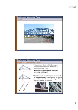
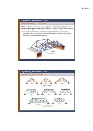
1. It defines the key features of a truss, including that it consists of slender straight members connected at joints, with pinned connections that allow only axial forces in the members.
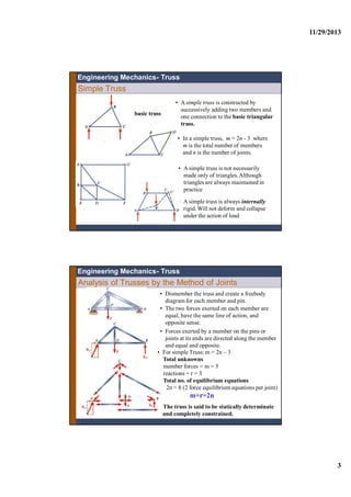
2. External loads must be applied at the joints, as members cannot support lateral loads. Most structures use multiple trusses joined together to form a space framework.
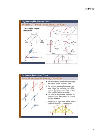
3. Simple trusses are constructed by adding members and joints, following the rule that m = 2n - 3, where m is the number of members and n is the number of joints. Simple trusses are internally rigid.
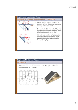
4. Two common methods for analyzing trusses
![11/29/2013
11
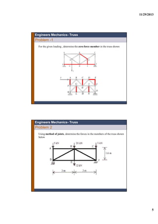
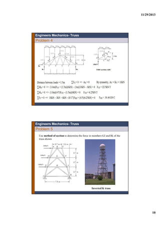
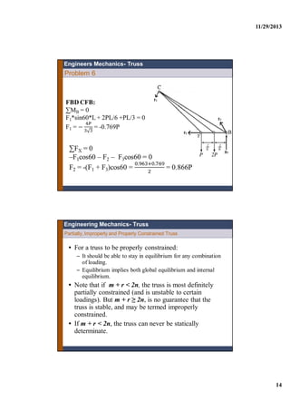
Problem-5
Engineers Mechanics- Truss
100kN
100kN
100kN
G
Solution JX = -300
KY = -JY = 100*(2.7 + 5.4 +8.1)/7.5 = 1620/7.5 = 216
Section XX, lower FBD,
∑MG = 0
-FKI [ 5.9( ] + JY(0.8) –JX(2.7) – KY(6.7) = 0
FKI = -143.19 kN (C )
∑MI = 0
FJG[ 5.9 ( ] + JY(6.7) –JX(2.7) – KY(0.8) = 0
FJG = 143.19 kN (T )
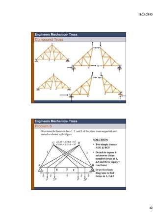
Compound Truss
• Compound trusses are composed of two or more
simple trusses . The trusses shown are statically
determinant, rigid, and completely constrained,
nrm 2
Engineers Mechanics- Truss](https://image.slidesharecdn.com/lecturetrusscompatibilitymode-160126134009/85/Lecture-truss-compatibility-mode-11-320.jpg)


](https://cdn.slidesharecdn.com/ss_thumbnails/virtualworkmodifiedcompatibilitymode1-160126134241-thumbnail.jpg?width=640&height=640&fit=bounds)


![Lecture 3 d_equilibrium [compatibility mode]](https://cdn.slidesharecdn.com/ss_thumbnails/lecture3dequilibriumcompatibilitymode-160126133858-thumbnail.jpg?width=640&height=640&fit=bounds)


![Vector mechanics [compatibility mode]](https://cdn.slidesharecdn.com/ss_thumbnails/vectormechanicscompatibilitymode-160126114336-thumbnail.jpg?width=640&height=640&fit=bounds)


