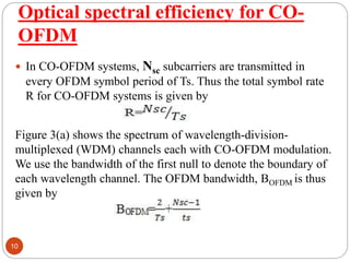
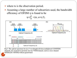
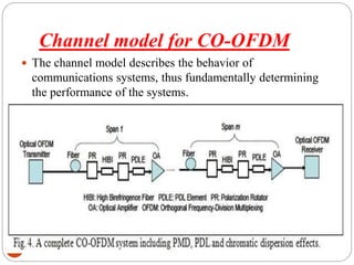
Principle of orthogonal frequency-division multiplexing (OFDM)
Optical transmitter for CO-OFDM
Optical spectral efficiency for CO-OFDM
Channel model for CO-OFDM
The channel model describes the behavior of communications systems, thus fundamentally determining the performance of the systems
2. Principle of orthogonal frequency-
division multiplexing (OFDM)
2
The principles of orthogonal frequency division multiplexing
(OFDM) modulation have been in existence for several
decades. However, in recent years these techniques have
quickly moved out of textbooks and research laboratories and
into practice in modern communications systems. The
techniques are employed in data delivery systems over the
phone line, digital radio and television, and wireless
networking systems.
OFDM is a special form of a broader class of multi-carrier
modulation (MCM), a generic implementation of which is
depicted in Fig. 1.
3. 3
The structure of a complex mixer (IQ modulator/demodulator),
which is commonly used in MCM systems, is also shown in the
figure. The MCM transmitted signal s(t) is represented as
where cki is the ith information symbol at the kth subcarrier, k s is the
waveform for the kth subcarrier, Nsc is the number of subcarriers, fk is the
frequency of the subcarrier, and Ts is the symbol period. The optimum
detector for each subcarrier could use a filter that matches the subcarrier
waveform, or a correlation matched to the subcarrier as shown in Fig. 1.
Therefore, the detected information symbol c′ ik at the output of the correlator is
given by :
5. 5
The classical MCM uses non-overlapped band limited
signals, and can be implemented with a bank of large
number of oscillators and filters at both transmit and
receive end.
The major disadvantage of MCM is that it requires
excessive bandwidth. This is because in order to design
the filters and oscillators cost-efficiently, the channel
spacing has to be multiple of the symbol rate, greatly
reducing the spectral efficiency.
6. 6
A fundamental challenge with the OFDM is that a
large number of subcarriers are needed so that the
transmission channel affects each subcarrier as a flat
channel. This leads to an extremely complex
architecture involving many oscillators and filters at
both transmit and receive end.
A generic optical OFDM system can be divided into
five functional blocks including
(i) the RF OFDM transmitter,
(ii) the RF-to-optical (RTO) up-converter,
(iii) the optical channel,
(iv) the optical-to-RF (OTR) down-converter, and
(v) the RF OFDM receiver.
8. Optical transmitter for CO-OFDM
8
The primary design goal for CO-OFDM is to construct a linear
transformation system.
The Mach-Zehnder modulators (MZM) characteristic has been
extensively investigated.
9. 9
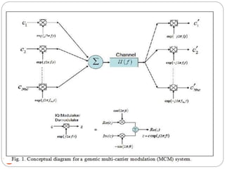
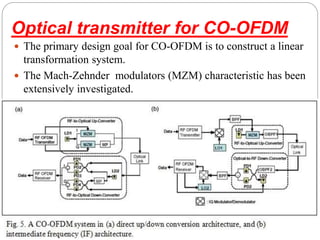
Figures 1(a) and 1(b) show respectively a CO-OFDM system
which uses direct up/down conversion architecture and
intermediate frequency (IF) architecture.
In the direct up conversion architecture , the optical transmitter
uses an optical I/Q modulator which comprises two MZMs to up
convert the real/imaginary parts of the s(t) [Eq. (1)].
In the direct down-conversion architecture, the OFDM optical
receiver uses.
Two pairs of balanced receivers and an optical 90° hybrid to
perform optical I/Q detection. The RF OFDM receiver performs
OFDM base-band processing to recover the data.
The advantages for such a direct-conversion architecture are
(i) elimination of a need for image rejection filter in both transmitter
and receiver, and
(ii) reduction of the required electrical bandwidth for both transmitter
and receiver.
10. Optical spectral efficiency for CO-
OFDM
10
In CO-OFDM systems, Nsc subcarriers are transmitted in
every OFDM symbol period of Ts. Thus the total symbol rate
R for CO-OFDM systems is given by
Figure 3(a) shows the spectrum of wavelength-division-
multiplexed (WDM) channels each with CO-OFDM modulation.
We use the bandwidth of the first null to denote the boundary of
each wavelength channel. The OFDM bandwidth, BOFDM is thus
given by
11. 11
where ts is the observation period.
Assuming a large number of subcarriers used, the bandwidth
efficiency of OFDM η is found to be
12. Channel model for CO-OFDM
12
The channel model describes the behavior of
communications systems, thus fundamentally determining
the performance of the systems.
13. some modern applications
13
• Long-haul 100 Gbps and higher data rate
transmission systems.
• High-speed multi-mode fiber transmission for
interconnects in data centers and high performance
computing.
• Optical Ethernet in Automotive.