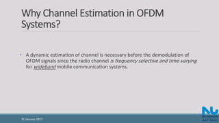
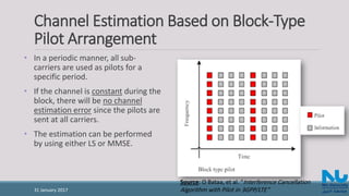
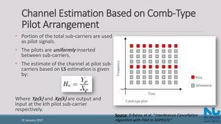
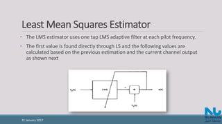
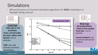
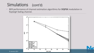
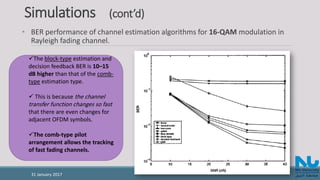
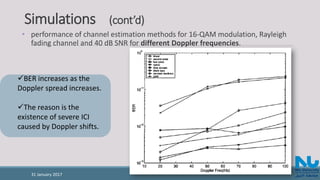
The document discusses channel estimation techniques for OFDM systems, highlighting the importance of dynamic channel estimation for effective demodulation due to the frequency selective and time-varying nature of radio channels. It covers block-type and comb-type pilot arrangements, including interpolation methods for estimating channels at data sub-carriers, and presents simulation results showing the performance of various estimation algorithms under different modulation schemes and fading conditions. The study, published in IEEE Transactions on Broadcasting, has been widely cited in the literature.


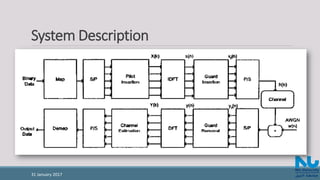
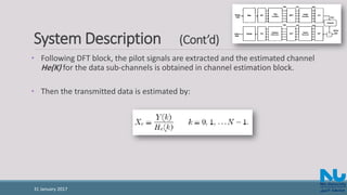
![System Description (Cont’d)
• The received signal is given by:
where h(n) is the channel impulse response and w(n) is Additive White Gaussian
Noise (AWGN).
• The channel response can be represented by [1]:
31 January 2017](https://image.slidesharecdn.com/channelestimationtechniquesbasedonpilotarrangementinofdmsystems-170131113914/85/Channel-Estimation-Techniques-Based-on-Pilot-Arrangement-in-OFDM-Systems-6-320.jpg)


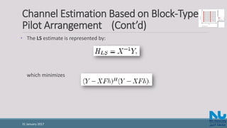
![Channel Estimation Based on Block-Type
Pilot Arrangement (Cont’d)
• If the time domain channel vector h is Gaussian and uncorrelated with the
channel noise W, then the frequency domain MMSE estimate of is given from
[2] as:
31 January 2017](https://image.slidesharecdn.com/channelestimationtechniquesbasedonpilotarrangementinofdmsystems-170131113914/85/Channel-Estimation-Techniques-Based-on-Pilot-Arrangement-in-OFDM-Systems-11-320.jpg)


![Interpolation Techniques in Comb-Type Pilot
Arrangement (Cont’d)
• Low-pass interpolation
Performed by inserting zeros into the original sequence and then applying a low-pass FIR
filter that allows the original data to pass through unchanged and interpolates between such
that the mean-square error between the interpolated points and their ideal values is
minimized.
• Time domain interpolation
A high-resolution interpolation based on zero-padding and DFT/IDFT [8].
31 January 2017](https://image.slidesharecdn.com/channelestimationtechniquesbasedonpilotarrangementinofdmsystems-170131113914/85/Channel-Estimation-Techniques-Based-on-Pilot-Arrangement-in-OFDM-Systems-16-320.jpg)
![References
• [1] R. Steele, Mobile Radio Communications. London, England: Pentech Press
Limited, 1992.
• [2] O. Edfors, M. Sandell, J. J. van de Beek, S. K. Wilson and P. Ola Borjesson,
"OFDM channel estimation by singular value decomposition," Proceedings of
Vehicular Technology Conference - VTC, Atlanta, GA, 1996.
• [3]Yuping Zhao and Aiping Huang, "A novel channel estimation method for
OFDM mobile communication systems based on pilot signals and transform-
domain processing," 1997 IEEE 47th Vehicular Technology Conference.
Technology in Motion, Phoenix, AZ, 1997.
31 January 2017](https://image.slidesharecdn.com/channelestimationtechniquesbasedonpilotarrangementinofdmsystems-170131113914/85/Channel-Estimation-Techniques-Based-on-Pilot-Arrangement-in-OFDM-Systems-22-320.jpg)