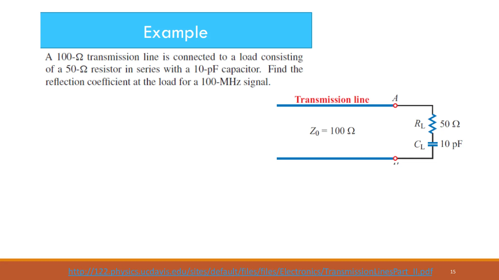
Waves on
Transmission Lines
8TH OCTOBER 2019
1
Transmission lines
•A transmission line is used for the transmission of electrical power from generating
substation to the various distribution units. It transmits the wave of voltage and
current from one end to another.
•Any transmission line can be simply represented by a pair of parallel wires into one
end of which power is fed by an a.c. generator.
2
https://en.wikipedia.org/wiki/Transmission_line#/media/File:Transmission_line_symbols.svg
Transmission line
Wave equations for both voltage and
current in a transmission line
•In the deriving the wave equation, a short element of the line is considered.
•Transmission line parameters are composed of resistance, inductance, conductance
and capacitance.
• The flowing currents gives rise to the combined inductance L0 H per unit length.
•Between the lines, which form a capacitor, there is an electrical capacitance C0 F per
unit length.
•Resistance in the line is represented by R0  per unit length.
•Conductance due to an imperfect insulating property of the insulator between the two
conductors can be designated as G0 S per unit length.
3
Distributed element in a transmission line
4
https://behindthesciences.com/microwaves-propagation/distributed-element-model-in-transmission-lines-part-ii/
These parameters vary according to the type of line.
Ideal or lossless transmission line
•In the absence of any resistance and conductance;i.e. R0 = G0 =0, only L0 and C0 completely
describe the line, which is known as ideal or lossless.
5
• Representation of element of an ideal
transmission line length dx.
• The inductanceof the element is L0dx
and capacitanceof the element is C0dx.
Derivation of the voltage and current waves
VOLTAGE W
AVE EQUATION
•If the rate of change of voltage per unit length at
constant time is V/x.
•The voltage difference between the ends of the element
dx is (V/x)dx, which is equals the voltage drop from
the inductance -(L0dx)I/t
•Since 2/xt = 2/tx, a pure wave equation for the
voltage with a velocity of propagation given by
v2 = 1/L0C0 is
CURRENT W
AVE EQUATION
•If the rate of change of current per unit length at constant
time is I/x, there is a loss of current along the length
dx of -(I/x)dx.
•The loss is because some current has charged the
capacitance C0dx of the line to a voltage V.
•If the amount of charge is q = (C0dx)V,
•So that
•Since 2/xt = 2/tx, a pure wave equation for the
current with a velocity of propagation given by
v2 = 1/L0C0 is
6
( )
0
0
V I
dx L dx
x t
V I
L
x t
 
= −
 
 
 = −
 
( )
0 differential current through C
;
dq
dI C dx V
dt t

= =

( )
0 0
I I
dx C dx V C V
x t x t
   
− =  − =
   
2 2
0 0
2 2
V V
L C
x t
 
=
 
2 2
0 0
2 2
I I
L C
x t
 
=
 
2 2
0 0
2 2
I I
L C
x t
 
=
 
Coaxial cables
•Many transmission lines are made in the
form of coaxial cables.
•The structure of the cables are composed
of a cylinder of dielectric material
having one conductor along its axis and
the other surrounding its outer surface.
7
https://www.slideshare.net/tafadzwagonera/presentation-on-different-modes-of-data-communication
Inductance per unit length and conductance
per unit length of coaxial cable
8
https://slideplayer.com/slide/1631556/
Characteristic impedance Z0
•The ratio of the voltage to the current in the waves travelling along the cable is
•Z0 is defined as the characteristic impedance if the impedance is seen by the
waves moving down an infinitely long cable.
• The impedance of the coaxial cablecan be written as
9
0
0
0
L
V
Z
I C
= =
0 0
0
0 0
0
0
1 1 1
2 2
where 376 6 and 1
ln ln
.
r
r
L b b
Z
C a a


   




= = =
=  
Characteristic impedance of a
transmission line (1)
•Recall the wave equationsof voltage and current waves
•The solutionsfor travelling wave propagating in the positivedirection are givens as
•The voltage and current relates to each othervia (V/x) = -(L0dx)I/t: the voltage drops across
an element length dx.
•This gives
10
2 2
0 0
2 2
V V
L C
x t
 
=
 
2 2
0 0
2 2
I I
L C
x t
 
=
 
( )
( )
0
0
2
2
sin
sin
V V vt x
I I vt x




+ +
+ +
= −
= −
0
V vL I
+ +
=
“+” refers to a wave moving in
the positive x-direction.
Both travelling waves are in phase.
•Subsequently, this gives
•The value of Z0 for the coaxial cable is found to be
•In common with the specificacousticimpedance, a negativesign is introducedto the ratio
when the waves are travellingin the negativex-direction.
•When waves are travelling in both directionsalong the transmission line, the total voltage and
current at any point will be given by
11
Characteristic impedance of a
transmission line (2)
0
0 0
0
L
V
vL Z
I C
+
+
= = =
0
1
2
ln
b
Z
a

 
=
V V V
I I I
+ −
+ −
= +
= +
Reflection from the end of a transmission line
•Supposethat transmission line of characteristic impedance Z0 has a finite length and that the end
oppositethat of the generator is terminated by a load of impedance ZL.
•Provided that the boundaryconditionat ZL must be V++V- = VL, where VL is the voltage across
the load and I++I- =IL.
•In addition, V+/V- = Z0, V-/I- = -Z0 and VL/IL = ZL.
12
Travelling wave to the right
Travelling wave to the left
Voltage amplitude
coefficient
Reflection coefficient
Transmission coefficient
Current amplitude
coefficient
Reflection coefficient
Transmission coefficient
13
0
0
L
L
Z Z
V
V Z Z
−
+
−
=
+
0
2
L L
L
V Z
V Z Z
+
=
+
0
0
L
L
Z Z
I
I Z Z
−
+
−
=
+
0
0
2
L
L
Z
I
I Z Z
+
=
+
It is clear that if the line is terminated by a load ZL = Z0, its characteristic impedance, the line
is matched, all the energy propagating down the line is absorbed and there is no reflected wave.
Derivation of the reflection coefficient
•Starting with V++V- = VL and I++I- =IL , derive
14
0
0
L
L
Z Z
V
V Z Z
−
+
−
=
+
15
http://122.physics.ucdavis.edu/sites/default/files/files/Electronics/TransmissionLinesPart_II.pdf
16
Solution
( )( )
( )
8 11
0
0
1
load impedance Z
2
1
=50
2 10 10
=50 159
50 159 100
reflection coefficient =
L c
L
L
R iX R i
fC
i
i
i
Z Z
V
V Z Z

 −
−
+
= − = −
−
−
− −
−
=
+ ( )
( )
0
59
50 159 100
=0.77
i
i
e
− −
Short circuited transmission line (ZL = 0)
•If the ends of the transmission line are short circuited, we have
•This gives V+ = -V and there is total reflection with a phase change of .
•This is the condition for the existence of standing waves.
•The figure shows that the voltage and current standing waves are out of phase in space by 900.
•In addition, both of them are also out of phase by 900 in time.
17
0
L
V V V
+ −
= + =
Derivation of the voltage and current standing
waves at any point along the transmission line.
•At any position x on the line, the two voltage waves may be written as
•With the total reflection and  phase shift, V0+ = -V0-,
•The total voltage at x is
•The total current at x is
•Can you see the phase difference between voltage and current in space and time?
18
( )
( )
0 0
0 0
i t kx
i t kx
V Z I V e
V Z I V e


−
+ + +
+
− − −
= =
= − =
( ) ( ) ( )
0 0
2 sin
ikx ikx i t i t
x
V V V V e e e i V e kx
 
−
+ − +
= + = − = −
( ) ( )
0 0
0 0
2
cos
ikx ikx i t i t
x
V V
I I I e e e e kx
Z Z
 
−
+
+ −
= + = + =
Effect of resistance in a transmission line
•In practice, some resistance always exists in the wires which will be responsiblefor energy losses.
•The transmission line is supposed to have a series resistance R0  per unit length and a short circuiting or
shuntingresistance between the wire.
•The inverse shunt resistance is representedas a shunt conductance G0 (siemens per meter).
•Current will now leak across the transmission line because the dielectricis not perfect.
19
Real transmission line element includesa series resistance R0  per unit length and
a shunt conductanceG0 S per unit length
Travelling waves in a transmission line
with resistance (1)
•Recall the voltage and current changes across the line element length dx in case of lossless line,
•Now, adding the resistance R0 and conductanceG0 to the equation,
•Inserting /x into one of the above equation gives
20
0 0
and
V I I
L C V
x t x t
   
= − = −
   
( )
( )
0 0 0 0 0
0 0 0 0 0 0
-
where and
,
; i t i t
V I
L R I R i L I
x t
I
C V G V G i C V V V e I I e
x t
 


 
= − = − +
 
 
= − − = − + = =
 
( ) ( )( )
( )( )
2
2
0 0 0 0 0 0
2
2
0 0 0 0
where which may be written as =
V I
R i L R i L G i C V V
x
x
R i L G i C ik
   
    
 
= − + = + + =


= + + +
Propagation
constant
Attenuation or
absorption
coefficient
Wave
number
•Similarly, the differential equationfor the current may written as
•It is clear that the solutionsfor x-dependenceof are of the form
•The completesolution with the time-dependenceterm exp(it) may be written as
21
Travelling waves in a transmission line
with resistance (2)
( ) ( )( )
2
2
0 0 0 0 0 0
2
I V
G i C R i L G i C I I
x
x
   
 
= − + = + + =


2
2
2
V
V
x


=

or ;where and are constants.
x x
V Ae V Be A B
 
− +
= =
( ) ( ) ( )
i t kx i t kx
x x i t x x
V Ae Be e Ae e Be e
 
    
− +
− + −
= + = +
•Voltage and current waves in both directions along a transmission line with resistance.
The effect of the dissipation term is shown by the exponentiallydecaying wave in each direction.
•Note that, the behavior of the current wave I is exactly similar.
•Since power is the product VI, the power loss with distance varies as
22
( )
2
x
e 
−
Characteristic impedance of a
transmission line with resistance
•Let’s consider one of the solution to the equation 2I/x2 = 2I,
•Recall , this leads to
•Or
23
;the current wave in the positive x-direction.
x
I A e 
−

=
( )
0 0
I
G i C V
x


= − +

( ) ( )
0 0
x
A e G i C V

 
−

− = − +
( )( )
( )
( )
( )
0 0 0 0
0 0
0 0
0
0 0
x
I
R i L G i C
A e V
G i C
R i L
V
Z
I G i C

 



+
−
+
+
+
 
+ +
 
 =
 
+
 
+

 = =
+
1 2 3
Similarly,
( )
( )
0 0
0
0 0
R i L
V
Z
I G i C


−
−
+

 = = −
+

High voltage Engg. Waves on Transmission Lines.pdf

  • 1.
  • 2.
    Transmission lines •A transmissionline is used for the transmission of electrical power from generating substation to the various distribution units. It transmits the wave of voltage and current from one end to another. •Any transmission line can be simply represented by a pair of parallel wires into one end of which power is fed by an a.c. generator. 2 https://en.wikipedia.org/wiki/Transmission_line#/media/File:Transmission_line_symbols.svg Transmission line
  • 3.
    Wave equations forboth voltage and current in a transmission line •In the deriving the wave equation, a short element of the line is considered. •Transmission line parameters are composed of resistance, inductance, conductance and capacitance. • The flowing currents gives rise to the combined inductance L0 H per unit length. •Between the lines, which form a capacitor, there is an electrical capacitance C0 F per unit length. •Resistance in the line is represented by R0  per unit length. •Conductance due to an imperfect insulating property of the insulator between the two conductors can be designated as G0 S per unit length. 3
  • 4.
    Distributed element ina transmission line 4 https://behindthesciences.com/microwaves-propagation/distributed-element-model-in-transmission-lines-part-ii/ These parameters vary according to the type of line.
  • 5.
    Ideal or losslesstransmission line •In the absence of any resistance and conductance;i.e. R0 = G0 =0, only L0 and C0 completely describe the line, which is known as ideal or lossless. 5 • Representation of element of an ideal transmission line length dx. • The inductanceof the element is L0dx and capacitanceof the element is C0dx.
  • 6.
    Derivation of thevoltage and current waves VOLTAGE W AVE EQUATION •If the rate of change of voltage per unit length at constant time is V/x. •The voltage difference between the ends of the element dx is (V/x)dx, which is equals the voltage drop from the inductance -(L0dx)I/t •Since 2/xt = 2/tx, a pure wave equation for the voltage with a velocity of propagation given by v2 = 1/L0C0 is CURRENT W AVE EQUATION •If the rate of change of current per unit length at constant time is I/x, there is a loss of current along the length dx of -(I/x)dx. •The loss is because some current has charged the capacitance C0dx of the line to a voltage V. •If the amount of charge is q = (C0dx)V, •So that •Since 2/xt = 2/tx, a pure wave equation for the current with a velocity of propagation given by v2 = 1/L0C0 is 6 ( ) 0 0 V I dx L dx x t V I L x t   = −      = −   ( ) 0 differential current through C ; dq dI C dx V dt t  = =  ( ) 0 0 I I dx C dx V C V x t x t     − =  − =     2 2 0 0 2 2 V V L C x t   =   2 2 0 0 2 2 I I L C x t   =   2 2 0 0 2 2 I I L C x t   =  
  • 7.
    Coaxial cables •Many transmissionlines are made in the form of coaxial cables. •The structure of the cables are composed of a cylinder of dielectric material having one conductor along its axis and the other surrounding its outer surface. 7 https://www.slideshare.net/tafadzwagonera/presentation-on-different-modes-of-data-communication
  • 8.
    Inductance per unitlength and conductance per unit length of coaxial cable 8 https://slideplayer.com/slide/1631556/
  • 9.
    Characteristic impedance Z0 •Theratio of the voltage to the current in the waves travelling along the cable is •Z0 is defined as the characteristic impedance if the impedance is seen by the waves moving down an infinitely long cable. • The impedance of the coaxial cablecan be written as 9 0 0 0 L V Z I C = = 0 0 0 0 0 0 0 1 1 1 2 2 where 376 6 and 1 ln ln . r r L b b Z C a a           = = = =  
  • 10.
    Characteristic impedance ofa transmission line (1) •Recall the wave equationsof voltage and current waves •The solutionsfor travelling wave propagating in the positivedirection are givens as •The voltage and current relates to each othervia (V/x) = -(L0dx)I/t: the voltage drops across an element length dx. •This gives 10 2 2 0 0 2 2 V V L C x t   =   2 2 0 0 2 2 I I L C x t   =   ( ) ( ) 0 0 2 2 sin sin V V vt x I I vt x     + + + + = − = − 0 V vL I + + = “+” refers to a wave moving in the positive x-direction. Both travelling waves are in phase.
  • 11.
    •Subsequently, this gives •Thevalue of Z0 for the coaxial cable is found to be •In common with the specificacousticimpedance, a negativesign is introducedto the ratio when the waves are travellingin the negativex-direction. •When waves are travelling in both directionsalong the transmission line, the total voltage and current at any point will be given by 11 Characteristic impedance of a transmission line (2) 0 0 0 0 L V vL Z I C + + = = = 0 1 2 ln b Z a    = V V V I I I + − + − = + = +
  • 12.
    Reflection from theend of a transmission line •Supposethat transmission line of characteristic impedance Z0 has a finite length and that the end oppositethat of the generator is terminated by a load of impedance ZL. •Provided that the boundaryconditionat ZL must be V++V- = VL, where VL is the voltage across the load and I++I- =IL. •In addition, V+/V- = Z0, V-/I- = -Z0 and VL/IL = ZL. 12 Travelling wave to the right Travelling wave to the left
  • 13.
    Voltage amplitude coefficient Reflection coefficient Transmissioncoefficient Current amplitude coefficient Reflection coefficient Transmission coefficient 13 0 0 L L Z Z V V Z Z − + − = + 0 2 L L L V Z V Z Z + = + 0 0 L L Z Z I I Z Z − + − = + 0 0 2 L L Z I I Z Z + = + It is clear that if the line is terminated by a load ZL = Z0, its characteristic impedance, the line is matched, all the energy propagating down the line is absorbed and there is no reflected wave.
  • 14.
    Derivation of thereflection coefficient •Starting with V++V- = VL and I++I- =IL , derive 14 0 0 L L Z Z V V Z Z − + − = +
  • 15.
  • 16.
    16 Solution ( )( ) () 8 11 0 0 1 load impedance Z 2 1 =50 2 10 10 =50 159 50 159 100 reflection coefficient = L c L L R iX R i fC i i i Z Z V V Z Z   − − + = − = − − − − − − = + ( ) ( ) 0 59 50 159 100 =0.77 i i e − −
  • 17.
    Short circuited transmissionline (ZL = 0) •If the ends of the transmission line are short circuited, we have •This gives V+ = -V and there is total reflection with a phase change of . •This is the condition for the existence of standing waves. •The figure shows that the voltage and current standing waves are out of phase in space by 900. •In addition, both of them are also out of phase by 900 in time. 17 0 L V V V + − = + =
  • 18.
    Derivation of thevoltage and current standing waves at any point along the transmission line. •At any position x on the line, the two voltage waves may be written as •With the total reflection and  phase shift, V0+ = -V0-, •The total voltage at x is •The total current at x is •Can you see the phase difference between voltage and current in space and time? 18 ( ) ( ) 0 0 0 0 i t kx i t kx V Z I V e V Z I V e   − + + + + − − − = = = − = ( ) ( ) ( ) 0 0 2 sin ikx ikx i t i t x V V V V e e e i V e kx   − + − + = + = − = − ( ) ( ) 0 0 0 0 2 cos ikx ikx i t i t x V V I I I e e e e kx Z Z   − + + − = + = + =
  • 19.
    Effect of resistancein a transmission line •In practice, some resistance always exists in the wires which will be responsiblefor energy losses. •The transmission line is supposed to have a series resistance R0  per unit length and a short circuiting or shuntingresistance between the wire. •The inverse shunt resistance is representedas a shunt conductance G0 (siemens per meter). •Current will now leak across the transmission line because the dielectricis not perfect. 19 Real transmission line element includesa series resistance R0  per unit length and a shunt conductanceG0 S per unit length
  • 20.
    Travelling waves ina transmission line with resistance (1) •Recall the voltage and current changes across the line element length dx in case of lossless line, •Now, adding the resistance R0 and conductanceG0 to the equation, •Inserting /x into one of the above equation gives 20 0 0 and V I I L C V x t x t     = − = −     ( ) ( ) 0 0 0 0 0 0 0 0 0 0 0 - where and , ; i t i t V I L R I R i L I x t I C V G V G i C V V V e I I e x t       = − = − +     = − − = − + = =   ( ) ( )( ) ( )( ) 2 2 0 0 0 0 0 0 2 2 0 0 0 0 where which may be written as = V I R i L R i L G i C V V x x R i L G i C ik            = − + = + + =   = + + + Propagation constant Attenuation or absorption coefficient Wave number
  • 21.
    •Similarly, the differentialequationfor the current may written as •It is clear that the solutionsfor x-dependenceof are of the form •The completesolution with the time-dependenceterm exp(it) may be written as 21 Travelling waves in a transmission line with resistance (2) ( ) ( )( ) 2 2 0 0 0 0 0 0 2 I V G i C R i L G i C I I x x       = − + = + + =   2 2 2 V V x   =  or ;where and are constants. x x V Ae V Be A B   − + = = ( ) ( ) ( ) i t kx i t kx x x i t x x V Ae Be e Ae e Be e        − + − + − = + = +
  • 22.
    •Voltage and currentwaves in both directions along a transmission line with resistance. The effect of the dissipation term is shown by the exponentiallydecaying wave in each direction. •Note that, the behavior of the current wave I is exactly similar. •Since power is the product VI, the power loss with distance varies as 22 ( ) 2 x e  −
  • 23.
    Characteristic impedance ofa transmission line with resistance •Let’s consider one of the solution to the equation 2I/x2 = 2I, •Recall , this leads to •Or 23 ;the current wave in the positive x-direction. x I A e  −  = ( ) 0 0 I G i C V x   = − +  ( ) ( ) 0 0 x A e G i C V    −  − = − + ( )( ) ( ) ( ) ( ) 0 0 0 0 0 0 0 0 0 0 0 x I R i L G i C A e V G i C R i L V Z I G i C       + − + + +   + +    =   +   +   = = + 1 2 3 Similarly, ( ) ( ) 0 0 0 0 0 R i L V Z I G i C   − − +   = = − +